Page 4060 of 4770

(c) (d) SF±26
± SFI (5S±FE)INJECTOR
1459 Author�: Date�:
(h) Attach the 4 injectors and delivery pipe assembly t")
B06352
S05976
Upward
Turn
Connector
B06351
Gray
Brown No.1
No.2
No.3
No.4
S05289
(b)
(c) (d) SF±26
± SFI (5S±FE)INJECTOR
1459 Author�: Date�:
(h) Attach the 4 injectors and delivery pipe assembly to the
cylinder head.
(i) Temporarily install the 2 bolts holding the delivery pipe to
the cylinder head.
(j) Check that the injectors rotate smoothly.
HINT:
If injectors do not rotate smoothly, the probable cause is incor-
rect installation of O±rings. Replace the O±rings.
(k) Position the injector connector upward.
(l) Tighten the 2 bolts holding the delivery pipe to the cylinder
head.
Torque: 13 N´m (130 kgf´cm, 9 ft´lbf)
(m) Connect the 4 injector connectors.
HINT:
The No.1 and No.3 injector connectors are brown, and the No.2
and No.4 injector connectors are gray.
2. INSTALL CYLINDER HEAD COVER
(a) Install the cylinder head cover. (See page EM±53)
(b) Connect the PCV hose to the intake manifold.
(c) Connect the PCV hose to the cylinder head cover.
(d) Install the engine wire clamp to the mounting bolt of the
No.2 timing belt cover.
(e) Connect the 4 high±tension cords to the spark plugs.
(f) Install the 4 high±tension cords to the clamps on the cylin-
der head cover.
3. CHECK FOR FUEL LEAKS (See page SF±1)
Page 4177 of 4770

The inflater and bag of the")
RS0ET±01
W03512
R09725Spiral Cable
W03511
H01347
H02610
RS±2
± SUPPLEMENTAL RESTRAINT SYSTEMSRS AIRBAG
2147 Author�: Date�:
OPERATION
1. STEERING WHEEL PAD (with AIRBAG)
The inflater and bag of the SRS are stored in the steering wheel
pad and cannot be disassembled. The inflater contains a squib,
igniter charge, gas generant, etc., and inflates the bag when
instructed by the airbag sensor assembly.
2. SPIRAL CABLE (in COMBINATION SWITCH)
A spiral cable is used as an electrical joint from the vehicle body
side to the steering wheel.
3. FRONT PASSENGER AIRBAG ASSEMBLY
The inflater and bag of the SRS are stored in the front passen-
ger airbag assembly and cannot be disassembled. The inflater
contains a squib, igniter charge and gas generant, etc., and in-
flates the bag when instructed by the airbag sensor assembly.
4. SIDE AIRBAG ASSEMBLY
The inflater and bag of the SRS side airbag are stored in the
side airbag assembly and cannot be disassembled. The inflater
contains a squib, igniter charge and gas generant, etc., and in-
flates the bag when instructed by the side airbag sensor assem-
bly.
5. SEAT BELT PRETENSIONER
The seat belt pretensioner system is a component of the front
seat outer belt. The pretensioner contains a squib, gas gener-
ant, wire, piston, etc., and operates in the event of a frontal colli-
sion.
Page 4179 of 4770
H08316
Side Airbag Assembly (LH)
(Squib) Side Airbag Sensor (LH)Side Airbag Sensor (RH) Side Airbag Assembly (RH)
(Squib)
Seat Belt
Pretensioner (RH)
Airbag Sensor
AssemblyFront Passenger Airbag Assembly (Squib)
Spiral Cable
No.1 J/B 2
37 8
10
11
12
13
1
4
5
6
9
Steering Wheel
Pad (Squib) Front Airbag Sensor (RH)
Front Airbag Sensor (LH)
Seat Belt
Pretensioner (LH) 14
15
16
RS±4
± SUPPLEMENTAL RESTRAINT SYSTEMSRS AIRBAG
2149 Author�: Date�:
10. TMC made:
SRS CONNECTORS
No.ItemApplication
(1)Terminal Twin±Lock MechanismConnectors 1, 2, 3, 4, 5, 6, 7, 8, 9, 10, 11, 12, 13, 14, 15, 16
(2)Airbag Activation Prevention MechanismConnectors 1, 2, 3, 4, 5, 7, 8, 9, 15, 16
(3)Electrical Connection Check MechanismConnectors 1, 2, 3
(4)Connector Twin±Lock MechanismConnectors 5, 6, 7
Page 4180 of 4770
H08247
Airbag Sensor
Assembly2
31
Side Airbag Assembly (RH)
(Squib)
Seat Belt
Pretensioner (RH)
Side Airbag Sensor (RH)
Front Passenger Airbag
Assembly (Squib)
Spiral Cable
Steering Wheel
Pad (Squib)
No.1 J / B
Side Airbag Sensor (LH)
Side Airbag Assembly (LH)
(Squib)
4
5
6
7
14
9
10
1112
13
8
15
Seat Belt
Pretensioner (LH)
16
17
18
Front Airbag Sensor (RH)
Front Airbag Sensor (LH)
± SUPPLEMENTAL RESTRAINT SYSTEMSRS AIRBAG
RS±5
2150 Author�: Date�:
11. TMMK made:
SRS CONNECTORS
No.ItemApplication
(1)Terminal Twin±Lock MechanismConnectors 1, 2, 3, 4, 5, 6, 7, 8, 9, 10, 11, 12, 13, 14, 15, 16,
17, 18
(2)Airbag Activation Prevention MechanismConnectors 1, 2, 3, 4, 5, 7, 8, 9, 15, 16, 17, 18
(3)Electrical Connection Check MechanismConnectors 1, 2, 3
(4)Connector Twin±Lock MechanismConnectors 5, 6, 7
Page 4243 of 4770
RS01Q±06
H03285: Specified torqueN´m (kgf´cm, ft´lbf)
Side Airbag Sensor Assembly
20 (205, 15)
Front Seat Outer Belt Retractor
42 (430, 31)
Center Pillar Lower Garnish
Front Door Scuff Plate
7.5 (76, 66 in.´lbf)
RS±68
± SUPPLEMENTAL RESTRAINT SYSTEMSIDE AIRBAG SENSOR ASSEMBLY
2213 Author�: Date�:
SIDE AIRBAG SENSOR ASSEMBLY
COMPONENTS
Page 4244 of 4770
RS01R±05
H01346
H01339
± SUPPLEMENTAL RESTRAINT SYSTEMSIDE AIRBAG SENSOR ASSEMBLY
RS±69
2214 Author�: Date�:
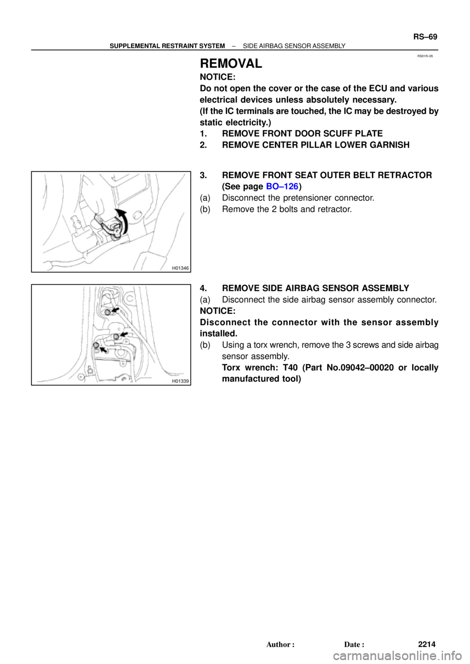
REMOVAL
NOTICE:
Do not open the cover or the case of the ECU and various
electrical devices unless absolutely necessary.
(If the IC terminals are touched, the IC may be destroyed by
static electricity.)
1. REMOVE FRONT DOOR SCUFF PLATE
2. REMOVE CENTER PILLAR LOWER GARNISH
3. REMOVE FRONT SEAT OUTER BELT RETRACTOR
(See page BO±126)
(a) Disconnect the pretensioner connector.
(b) Remove the 2 bolts and retractor.
4. REMOVE SIDE AIRBAG SENSOR ASSEMBLY
(a) Disconnect the side airbag sensor assembly connector.
NOTICE:
Disconnect the connector with the sensor assembly
installed.
(b) Using a torx wrench, remove the 3 screws and side airbag
sensor assembly.
Torx wrench: T40 (Part No.09042±00020 or locally
manufactured tool)
Page 4247 of 4770

RS05W±02
H01339
H01352
RS±72
± SUPPLEMENTAL RESTRAINT SYSTEMSIDE AIRBAG SENSOR ASSEMBLY
2217 Author�: Date�:
INSTALLATION
NOTICE:
�Never use SRS parts from another vehicle. When re-
placing parts, replace them with new ones.
�Never reuse the side airbag sensor assembly in-
volved in a collision when the airbag has deployed.
�Never repair a sensor in order to reuse it.
1. INSTALL SIDE AIRBAG SENSOR ASSEMBLY
(a) Using a torx wrench, install the side airbag sensor assem-
bly with the 3 screws.
Torx wrench: T40 (Part No.09042±00020 or locally
manufactured tool)
Torque: 20 N´m (205 kgf´cm, 15 ft´lbf)
(b) Connect the side airbag sensor assembly connector.
NOTICE:
�Connection of the connector is done after the sensor
assembly has been installed. Make sure the sensor
assembly is installed with the specified torque.
�If the sensor assembly has been dropped, or there are
cracks, dents or other defects in the case, bracket or
connector, replace the sensor assembly with a new
one.
�When installing the sensor assembly, take care that
the SRS wiring does not interfere with other parts and
is not pinched between other parts.
�After installation, shake the sensor assembly to
check that there is no looseness.
2. INSTALL FRONT SEAT OUTER BELT RETRACTOR
(See page BO±134)
(a) Install the retractor with the 2 bolts.
Torque:
Upper bolt: 7.5 N´m (76 kgf´cm, 66 in.´lbf)
Lower bolt: 42 N´m (430 kgf´cm, 31 ft´lbf)
(b) Connect the pretensioner connector.
3. INSTALL CENTER PILLAR LOWER GARNISH
4. INSTALL FRONT DOOR SCUFF PLATE
Page 4248 of 4770
RS01V±11
H08282
Spiral CableCombination Meter
(Warning Light)Front Passenger Airbag Assembly
Side Airbag Assembly (RH)
Side Airbag Sensor
Assembly (RH)
Seat Belt Pretensioner (RH) Steering Wheel Pad
(with Airbag)
Side Airbag Sensor
Assembly (LH)
Seat Belt Pretensioner (LH)
Side Airbag Assembly (LH)
Airbag Sensor Assembly
Front Airbag Sensor (RH)
Front Airbag
Sensor (LH)
± SUPPLEMENTAL RESTRAINT SYSTEMWIRE HARNESS AND CONNECTOR
RS±73
2218 Author�: Date�:
WIRE HARNESS AND CONNECTOR
LOCATION

(Squib) Side Airbag Sensor (LH)Side Airbag Sensor (RH) Side Airbag Assembly (RH)
(Squib)
Seat Belt
Pretensioner (RH)
Airbag Sensor
AssemblyFront Passenger Airbag Assem")

(Squib)
Seat Belt
Pretensioner (RH)
Side Airbag Sensor (RH)
Front Passenger Airbag
Assembly (Squib)
Spiral Cable
Steering Wheel
Pad (Squib)")

Side Airbag Sensor Assembly
20 (205, 15)
Front Seat Outer Belt Retractor
42 (430, 31)
Center Pillar Lower Garnish
Front Door Scuff Plate
7.5 (")
Front Passenger Airbag Assembly
Side Airbag Assembly (RH)
Side Airbag Sensor
Assembly (RH)
Seat Belt Pretensioner (RH) Steering Wheel Pad")