Page 4001 of 4770
SS0AQ±01
± SERVICE SPECIFICATIONSCHARGING (5S±FE)
SS±39
202 Author�: Date�:
CHARGING(5S±FE)
SERVICE DATA
BatterySpecific gravity (Except maintenance±free battery)
at 20°C (68°F)
Voltage (Maintenance±free battery) at 20°C (68°F)
1.25 ± 1.29
12.5 ± 12.9 V
Drive beltTension w/ A/C New belt
Used belt
w/o A/C New belt
Used belt165 ± 25 lbf
110 ± 10 lbf
125 ± 25 lbf
95 ± 20 lbf
GeneratorRated output
Rotor coil resistance at 20°C (68°F)
Slip ring diameter STD
Minimum
Brush exposed length STD
Minimum12 V 80 A
2.7 ± 3.1 W
14.2 ± 14.4 mm (0.559 ± 0.567 in.)
12.8 mm (0.504 in.)
10.5 mm (0.413 in.)
1.5 mm (0.059 in.)
Voltage
regulatorRegulating voltage13.5 ± 15.1 V
Page 4003 of 4770
SS07K±01
± SERVICE SPECIFICATIONSCHARGING (1MZ±FE)
SS±41
204 Author�: Date�:
CHARGING (1MZ±FE)
SERVICE DATA
BatteryVoltage at 20°C (68°F)12.5 ± 12.9 V
Drive belt
Tension
New belt
Used belt
175 ± 5 lbf
115 ± 20 lbf
GeneratorRated output
Rotor coil resistance at 20°C (68°F)
Slip ring diameter STD
Limit
Brush exposed length STD
Limit12 V 80 A
2.1 ± 2.5 W
14.2 ± 14.4 mm (0.559 ± 0.567 in.)
12.8 mm (0.504 in.)
10.5 mm (0.413 in.)
1.5 mm (0.059 in.)
Voltage
regulatorRegulating voltage13.5 ± 15.1 V
Page 4026 of 4770

SS06L±03
SS±64
± SERVICE SPECIFICATIONSSTEERING
227 Author�: Date�:
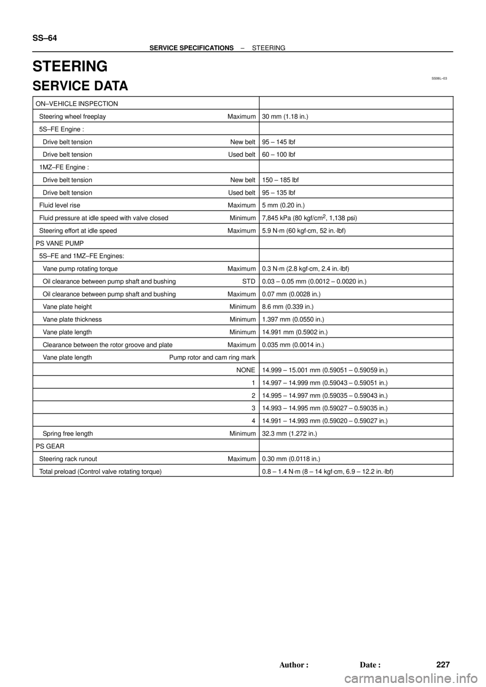
STEERING
SERVICE DATA
ON±VEHICLE INSPECTION
Steering wheel freeplayMaximum30 mm (1.18 in.)
5S±FE Engine :
Drive belt tension New belt95 ± 145 lbf
Drive belt tension Used belt60 ± 100 lbf
1MZ±FE Engine :
Drive belt tension New belt150 ± 185 lbf
Drive belt tension Used belt95 ± 135 lbf
Fluid level rise Maximum5 mm (0.20 in.)
Fluid pressure at idle speed with valve closed Minimum7,845 kPa (80 kgf/cm2, 1,138 psi)
Steering effort at idle speedMaximum5.9 N´m (60 kgf´cm, 52 in.´lbf)
PS VANE PUMP
5S±FE and 1MZ±FE Engines:
Vane pump rotating torqueMaximum0.3 N´m (2.8 kgf´cm, 2.4 in.´lbf)
Oil clearance between pump shaft and bushing STD0.03 ± 0.05 mm (0.0012 ± 0.0020 in.)
Oil clearance between pump shaft and bushingMaximum0.07 mm (0.0028 in.)
Vane plate heightMinimum8.6 mm (0.339 in.)
Vane plate thickness Minimum1.397 mm (0.0550 in.)
Vane plate lengthMinimum14.991 mm (0.5902 in.)
Clearance between the rotor groove and plateMaximum0.035 mm (0.0014 in.)
Vane plate length Pump rotor and cam ring mark
NONE14.999 ± 15.001 mm (0.59051 ± 0.59059 in.)
114.997 ± 14.999 mm (0.59043 ± 0.59051 in.)
214.995 ± 14.997 mm (0.59035 ± 0.59043 in.)
314.993 ± 14.995 mm (0.59027 ± 0.59035 in.)
414.991 ± 14.993 mm (0.59020 ± 0.59027 in.)
Spring free lengthMinimum32.3 mm (1.272 in.)
PS GEAR
Steering rack runout Maximum0.30 mm (0.0118 in.)
Total preload (Control valve rotating torque)0.8 ± 1.4 N´m (8 ± 14 kgf´cm, 6.9 ± 12.2 in.´lbf)
Page 4028 of 4770
SS061±17
SS±66
± SERVICE SPECIFICATIONSSUPPLEMENTAL RESTRAINT SYSTEM
229 Author�: Date�:
SUPPLEMENTAL RESTRAINT SYSTEM
TORQUE SPECIFICATION
Part tightenedN´mkgf´cmft´lbf
Steering wheel3536026
Steering wheel pad7.17263 in.´lbf
Front passenger airbag assembly x Instrument panel reinforcement2020515
Front seat installation bolt3737527
Seatback frame set bolt Bolt A
(See page RS±49) Bolt B18
15185
15013
11
Airbag sensor assembly2020515
Front airbag sensor2020515
Side airbag sensor assembly2020515
Front seat outer belt retractor Upper bolt
Lower bolt7.5
4276
43066 in.´lbf
31
Page 4032 of 4770

SS±70
± SERVICE SPECIFICATIONSBODY
233 Author�: Date�:
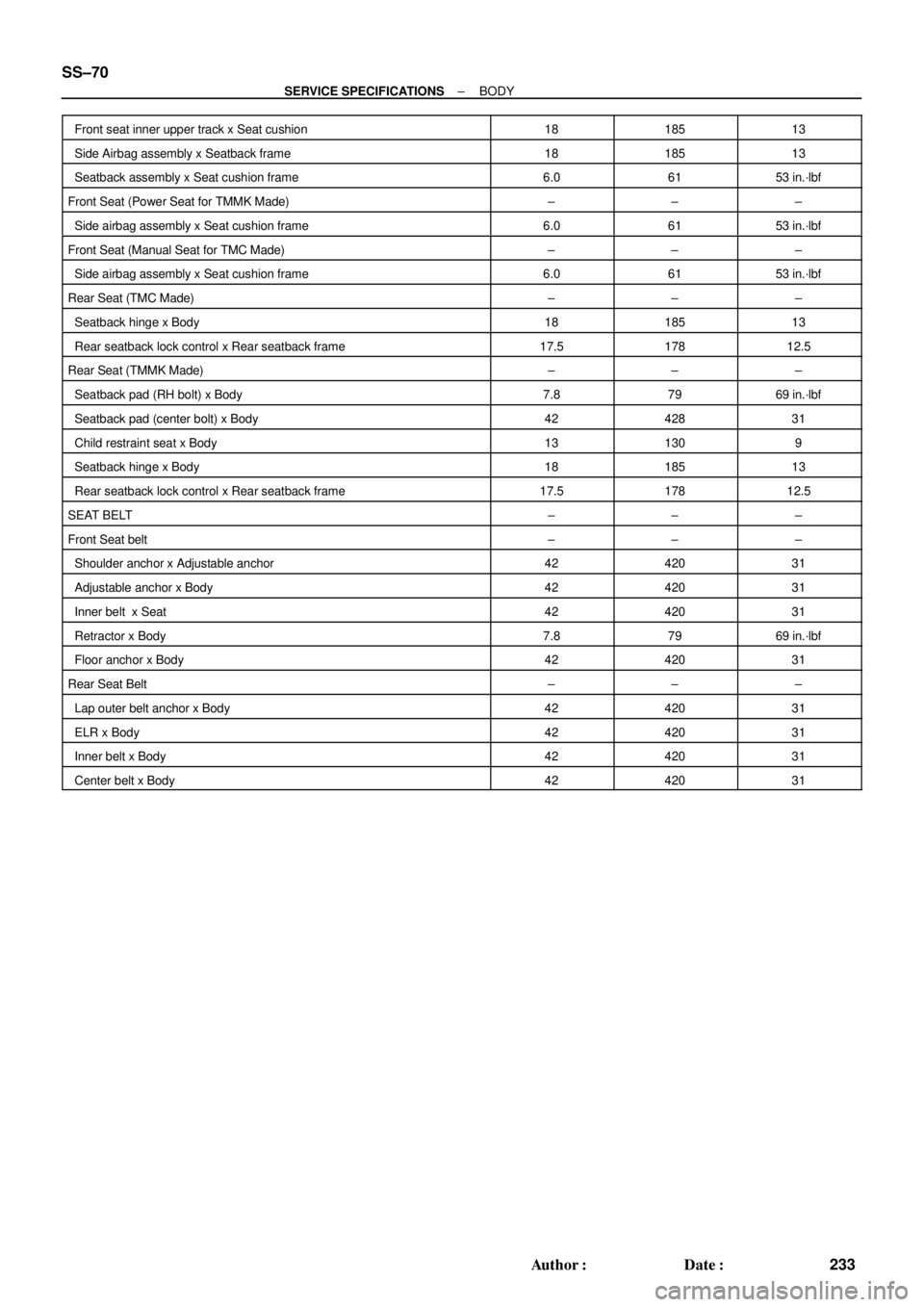
Front seat inner upper track x Seat cushion1818513
Side Airbag assembly x Seatback frame1818513
Seatback assembly x Seat cushion frame6.06153 in.´lbf
Front Seat (Power Seat for TMMK Made)±±±
Side airbag assembly x Seat cushion frame6.06153 in.´lbf
Front Seat (Manual Seat for TMC Made)±±±
Side airbag assembly x Seat cushion frame6.06153 in.´lbf
Rear Seat (TMC Made)±±±
Seatback hinge x Body1818513
Rear seatback lock control x Rear seatback frame17.517812.5
Rear Seat (TMMK Made)±±±
Seatback pad (RH bolt) x Body7.87969 in.´lbf
Seatback pad (center bolt) x Body4242831
Child restraint seat x Body131309
Seatback hinge x Body1818513
Rear seatback lock control x Rear seatback frame17.517812.5
SEAT BELT±±±
Front Seat belt±±±
Shoulder anchor x Adjustable anchor4242031
Adjustable anchor x Body4242031
Inner belt x Seat4242031
Retractor x Body7.87969 in.´lbf
Floor anchor x Body4242031
Rear Seat Belt±±±
Lap outer belt anchor x Body4242031
ELR x Body4242031
Inner belt x Body4242031
Center belt x Body4242031
Page 4033 of 4770
SS05V±02
± SERVICE SPECIFICATIONSAIR CONDITIONING
SS±71
234 Author�: Date�:
AIR CONDITIONING
SERVICE DATA
Refrigerant charge volume800 ± 50 g (28.22 ± 1.76 oz.)
Drive belt tension±
New belt165 ± 26 lbf
Used belt110 ± 11 lbf
Idle±up speed±
Magnetic clutch not engaged700 ± 50 rpm
Magnetic clutch engaged700 ± 50 rpm
Magnetic clutch clearance0.5 ± 0.15 mm (0.020 ± 0.0059 in.)
Page 4034 of 4770
SS05W±06
SS±72
± SERVICE SPECIFICATIONSAIR CONDITIONING
235 Author�: Date�:
TORQUE SPECIFICATION
Part tightenedN´mkgf´cmft´lbf
Compressor x Discharge hose101007
Compressor x Suction hose101007
Condenser x Disaharge hose101007
Condenser x Liquid tube1414010
Receiver x Liquid tube5.45548 in.´lbf
Expansion valve x Evaporator5.45548in.´lbf
Compressor x Engine2525018
Compressor x Compressor bracket (1MZ±FE Only)2525018
Drive belt adjusting bar bracket x Compressor2525018
Drive belt adjusting bar bracket x Adjusting bar1818513
Pivot bolt 5S±FE5252038Pivot bolt 5S FE
1MZ±FE5657041
Adjusting lock bolt1818513
Pressure switch x Liquied tube101007
Pressure plate x Compressor13.21359
Suction line (Piping joint)3233024
Suction line (Block joint)101007
Page 4056 of 4770

SF0DI±03
S05289
(c)
(e)
(d)
B06353
B06354
SF±22
± SFI (5S±FE)INJECTOR
1455 Author�: Date�:
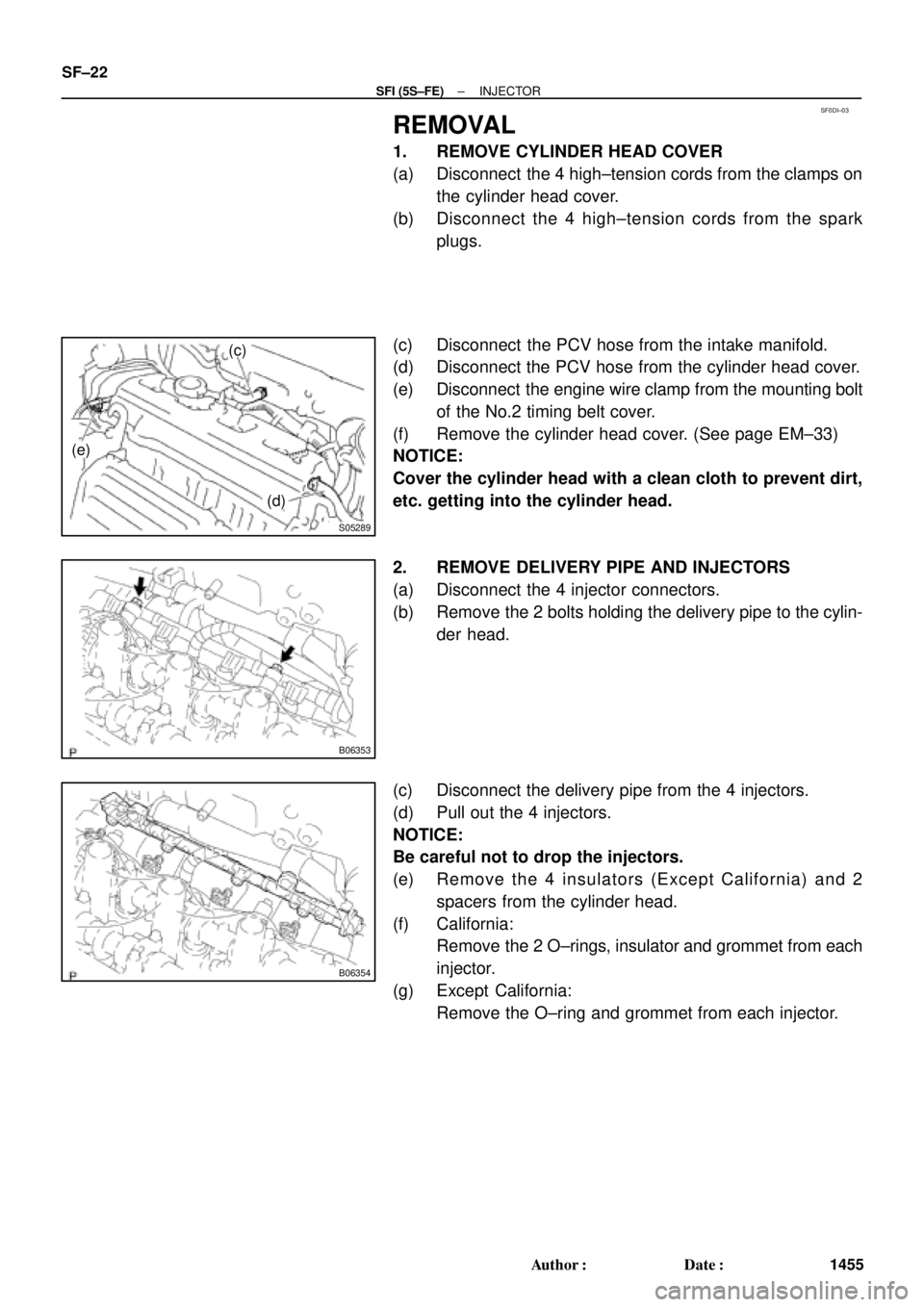
REMOVAL
1. REMOVE CYLINDER HEAD COVER
(a) Disconnect the 4 high±tension cords from the clamps on
the cylinder head cover.
(b) Disconnect the 4 high±tension cords from the spark
plugs.
(c) Disconnect the PCV hose from the intake manifold.
(d) Disconnect the PCV hose from the cylinder head cover.
(e) Disconnect the engine wire clamp from the mounting bolt
of the No.2 timing belt cover.
(f) Remove the cylinder head cover. (See page EM±33)
NOTICE:
Cover the cylinder head with a clean cloth to prevent dirt,
etc. getting into the cylinder head.
2. REMOVE DELIVERY PIPE AND INJECTORS
(a) Disconnect the 4 injector connectors.
(b) Remove the 2 bolts holding the delivery pipe to the cylin-
der head.
(c) Disconnect the delivery pipe from the 4 injectors.
(d) Pull out the 4 injectors.
NOTICE:
Be careful not to drop the injectors.
(e) Remove the 4 insulators (Except California) and 2
spacers from the cylinder head.
(f) California:
Remove the 2 O±rings, insulator and grommet from each
injector.
(g) Except California:
Remove the O±ring and grommet from each injector.