Page 3629 of 4770
N20974
(b)(b)
(a)
N21008
Clip
H01743
: 7 rivets
: clips
: clips
: clips BO±20
± BODYREAR DOOR
2378 Author�: Date�:
2001 CAMRY (RM819U)
7. REMOVE DOOR GLASS AND RUN
(a) Remove the bolt and nut holding the rear side frame to the
door.
(b) Remove the 2 bolts holding the door glass to the window
regulator.
Torque: 8.0 N´m (80 kgf´cm, 71 in.´lbf)
(c) Remove the rear side frame and the rear section of the
door glass run.
Torque: 5.5 N´m (55 kgf´cm, 49 in.´lbf)
HINT:
Pull the door glass run upward.
(d) Remove the door glass.
(e) Remove the entire door glass run.
HINT:
Pull the door glass run upward.
8. REMOVE REAR DOOR BELT MOULDING
Pry the rearward end of the rear door belt moulding from the
door and remove the moulding.
9. REMOVE REAR DOOR UPPER MOULDING
(a) Using a drill, cut the flange portion of the 5 rivets.
HINT:
Use 5 new rivets.
(b) Insert a screwdriver between the door and the rear door
upper moulding and pry it off.
Page 3657 of 4770
IG047±03
S05284
Engine Moving Control Rod
No.2 RH Engine Mounting Bracket
Generator Drive Belt
RH Front Fender Apron SealPS Pump Drive BeltGround Strap Connector
N´m (kgf´cm, ft´lbf) : Specified torque
64 (650, 47)
64 (650, 47)
52 (530, 38)
IG±10
± IGNITION (5S±FE)CRANKSHAFT POSITION SENSOR
1692 Author�: Date�:
CRANKSHAFT POSITION SENSOR
COMPONENTS
Page 3658 of 4770
S05938
No.2 Timing Belt
Cover
No.1 Timing Belt
Cover
Crankshaft
Pulley
Crankshaft Position Sensor
Connector
Crankshaft Position Sensor Wire ClampWire
Clamp
N´m (kgf´cm, ft´lbf):Specified torqueGenerator * Gasket
Timing Belt Guide Generator Wire
Generator Connector
Wire ClampWire
Clamp
108 (1,100, 80)
* Gasket
* Replace only if damaged
± IGNITION (5S±FE)CRANKSHAFT POSITION SENSOR
IG±11
1693 Author�: Date�:
Page 3681 of 4770

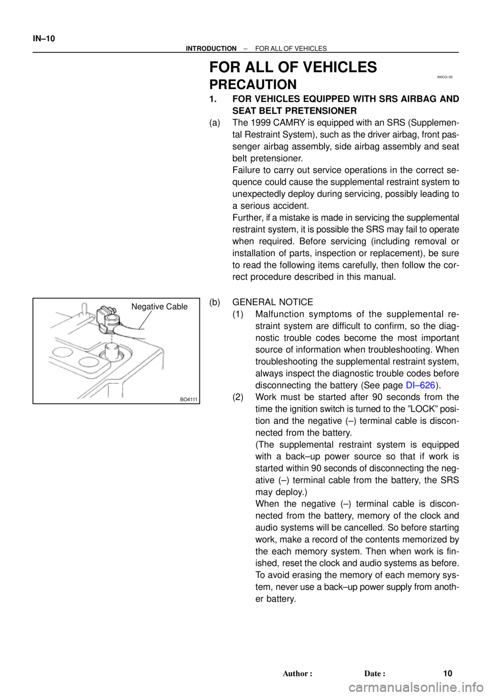
IN0CQ±03
BO4111
Negative Cable
IN±10
± INTRODUCTIONFOR ALL OF VEHICLES
10 Author�: Date�:
FOR ALL OF VEHICLES
PRECAUTION
1. FOR VEHICLES EQUIPPED WITH SRS AIRBAG AND
SEAT BELT PRETENSIONER
(a) The 1999 CAMRY is equipped with an SRS (Supplemen-
tal Restraint System), such as the driver airbag, front pas-
senger airbag assembly, side airbag assembly and seat
belt pretensioner.
Failure to carry out service operations in the correct se-
quence could cause the supplemental restraint system to
unexpectedly deploy during servicing, possibly leading to
a serious accident.
Further, if a mistake is made in servicing the supplemental
restraint system, it is possible the SRS may fail to operate
when required. Before servicing (including removal or
installation of parts, inspection or replacement), be sure
to read the following items carefully, then follow the cor-
rect procedure described in this manual.
(b) GENERAL NOTICE
(1) Malfunction symptoms of the supplemental re-
straint system are difficult to confirm, so the diag-
nostic trouble codes become the most important
source of information when troubleshooting. When
troubleshooting the supplemental restraint system,
always inspect the diagnostic trouble codes before
disconnecting the battery (See page DI±626).
(2) Work must be started after 90 seconds from the
time the ignition switch is turned to the ºLOCKº posi-
tion and the negative (±) terminal cable is discon-
nected from the battery.
(The supplemental restraint system is equipped
with a back±up power source so that if work is
started within 90 seconds of disconnecting the neg-
ative (±) terminal cable from the battery, the SRS
may deploy.)
When the negative (±) terminal cable is discon-
nected from the battery, memory of the clock and
audio systems will be cancelled. So before starting
work, make a record of the contents memorized by
the each memory system. Then when work is fin-
ished, reset the clock and audio systems as before.
To avoid erasing the memory of each memory sys-
tem, never use a back±up power supply from anoth-
er battery.
Page 3682 of 4770

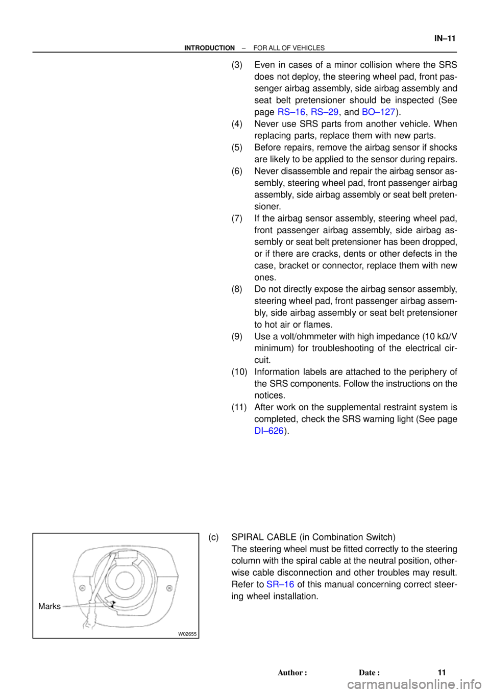
W02655
Marks
± INTRODUCTIONFOR ALL OF VEHICLES
IN±11
11 Author�: Date�:
(3) Even in cases of a minor collision where the SRS
does not deploy, the steering wheel pad, front pas-
senger airbag assembly, side airbag assembly and
seat belt pretensioner should be inspected (See
page RS±16, RS±29, and BO±127).
(4) Never use SRS parts from another vehicle. When
replacing parts, replace them with new parts.
(5) Before repairs, remove the airbag sensor if shocks
are likely to be applied to the sensor during repairs.
(6) Never disassemble and repair the airbag sensor as-
sembly, steering wheel pad, front passenger airbag
assembly, side airbag assembly or seat belt preten-
sioner.
(7) If the airbag sensor assembly, steering wheel pad,
front passenger airbag assembly, side airbag as-
sembly or seat belt pretensioner has been dropped,
or if there are cracks, dents or other defects in the
case, bracket or connector, replace them with new
ones.
(8) Do not directly expose the airbag sensor assembly,
steering wheel pad, front passenger airbag assem-
bly, side airbag assembly or seat belt pretensioner
to hot air or flames.
(9) Use a volt/ohmmeter with high impedance (10 kW/V
minimum) for troubleshooting of the electrical cir-
cuit.
(10) Information labels are attached to the periphery of
the SRS components. Follow the instructions on the
notices.
(11) After work on the supplemental restraint system is
completed, check the SRS warning light (See page
DI±626).
(c) SPIRAL CABLE (in Combination Switch)
The steering wheel must be fitted correctly to the steering
column with the spiral cable at the neutral position, other-
wise cable disconnection and other troubles may result.
Refer to SR±16 of this manual concerning correct steer-
ing wheel installation.
Page 3686 of 4770

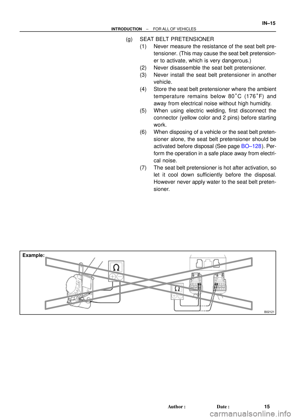
B02121
Example:
± INTRODUCTIONFOR ALL OF VEHICLES
IN±15
15 Author�: Date�:
(g) SEAT BELT PRETENSIONER
(1) Never measure the resistance of the seat belt pre-
tensioner. (This may cause the seat belt pretension-
er to activate, which is very dangerous.)
(2) Never disassemble the seat belt pretensioner.
(3) Never install the seat belt pretensioner in another
vehicle.
(4) Store the seat belt pretensioner where the ambient
temperature remains below 80°C (176°F) and
away from electrical noise without high humidity.
(5) When using electric welding, first disconnect the
connector (yellow color and 2 pins) before starting
work.
(6) When disposing of a vehicle or the seat belt preten-
sioner alone, the seat belt pretensioner should be
activated before disposal (See page BO±128). Per-
form the operation in a safe place away from electri-
cal noise.
(7) The seat belt pretensioner is hot after activation, so
let it cool down sufficiently before the disposal.
However never apply water to the seat belt preten-
sioner.
Page 3718 of 4770
LU03J±03
S05595
Engine Moving Control Rod
No.2 RH Engine Mounting Bracket
Generator Drive Belt
RH Front Fender Apron Seal
PS Pump Drive Belt
Exhaust Pipe Bracket
Oil Pan InsulatorGround Strap Connector
No.2 Rear End Plate
No.2 Exhaust
Manifold Stay
(TMMK Made)
(TMC Made)LH Stiffener Plate
� Gasket
Bracket
Front Exhaust Pipe
StayBracket� Gasket
N´m (kgf´cm, ft´lbf): Specified torque
� Non±reusable part
64 (650, 47)
52 (530, 38)
62 (630, 46)56 (570, 41) 64 (650, 47)
��
� LU±4
± LUBRICATION (5S±FE)OIL PUMP
1650 Author�: Date�:
OIL PUMP
COMPONENTS
Page 3719 of 4770
B06345
No.2 Timing Belt Cover
No.1 Timing Belt Cover* Gasket
Wire
ClampGeneratorGenerator Wire
Generator Connector
Crankshaft Pulley
No.2 Idler Pulley
Oil Pump Pulley
Crankshaft
Timing Pulley
Crankshaft Position SensorTiming Belt Guide
Wire ClampWire
Clamp
Timing Belt
Clamp
No.1 Idler Pulley
Tension Spring � GasketClamp
� Gasket
� GasketHigh±Tension Cord
Spark Plug
Oil Strainer
Drain Plug
N´m (kgf´cm, ft´lbf): Specified torque
� Non±reusable partx 17
* Gasket
* Replace only if damagedOil Pump
x 10
8.8 (90, 78 in.´lbf)5.4 (55, 48 in.´lbf)
5.4 (55, 48 in.´lbf)
24 (245, 18)
42 (425, 31)
108 (1,100, 80)
18 (180, 13)
42 (425, 31)
Oil Pan
± LUBRICATION (5S±FE)OIL PUMP
LU±5
1651 Author�: Date�: