Page 3578 of 4770
ENGINE UNIT
1358 Author�: Date�:
(k) Disconnect the brake booster vacuum hose from the air
intake chamber.
(l) Disconnect the engi")
S04497
B00881
Connector
Bracket
EM±72
± ENGINE MECHANICAL (1MZ±FE)ENGINE UNIT
1358 Author�: Date�:
(k) Disconnect the brake booster vacuum hose from the air
intake chamber.
(l) Disconnect the engine coolant reservoir hose from the
water outlet.
(m) Disconnect the heater hose from the intake manifold.
(n) Disconnect the heater hose from the water inlet housing.
(o) Disconnect the fuel inlet hose from the fuel filter.
CAUTION:
Perform disconnecting operation of the fuel tube connec-
tor (quick type) after observing the precautions.
(See page SF±6)
(p) Disconnect the purge hose from the pipe on the emission
control valve set.
(q) Disconnect the 2 vacuum hoses from the vacuum tank for
the ACIS.
12. DISCONNECT ENGINE WIRE FROM CABIN
(a) Remove the No.2 instrument lower panel.
(b) Disconnect the 3 ECM connectors.
(c) Disconnect the 3 cowl wire connectors from the connec-
tors on the bracket.
(d) Disconnect the grommet from the cowl panel, and pull out
the engine wire.
13. REMOVE DRIVE SHAFTS (See page SA±26)
14. M/T only:
REMOVE STARTER (See page ST±5)
15. M/T only:
DISCONNECT CLUTCH RELEASE CYLINDER AND
ACCUMULATOR WITHOUT DISCONNECTING TUBE
16. DISCONNECT A/C COMPRESSOR FROM ENGINE
(a) Disconnect the A/C compressor connector.
(b) Remove the drive belt.
(c) Remove the 4 bolts, nut and drive belt adjusting bar
bracket.
(d) Disconnect the A/C compressor from the engine.
17. DISCONNECT TRANSAXLE CONTROL CABLE(S)
FROM TRANSAXLE
Page 3579 of 4770
P18775
S05393
M/T
Z18907
A/T
P18752
A05426
± ENGINE MECHANICAL (1MZ±FE)ENGINE UNIT
EM±73
1359 Author�: Date�:
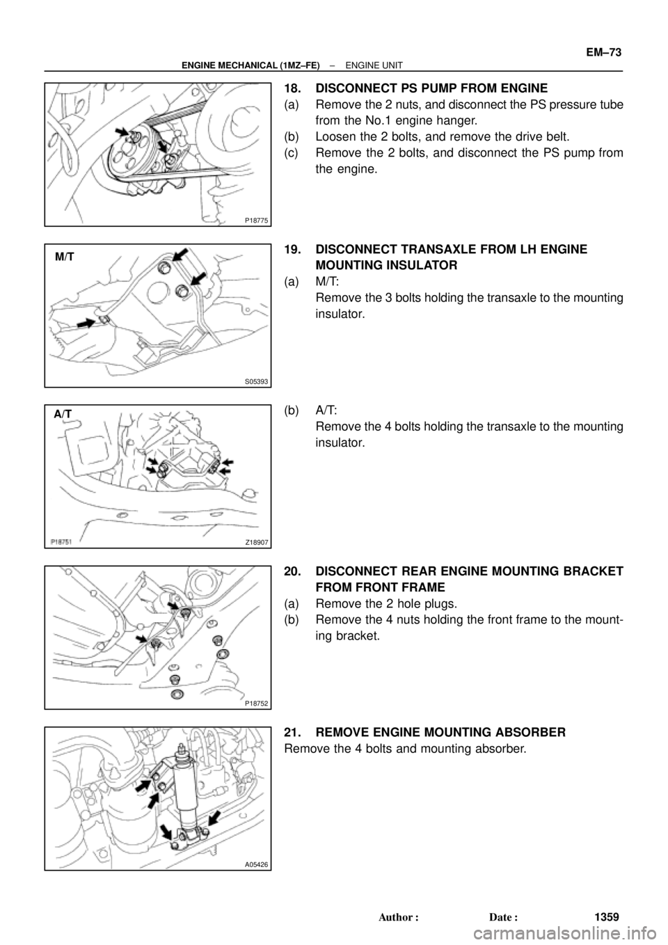
18. DISCONNECT PS PUMP FROM ENGINE
(a) Remove the 2 nuts, and disconnect the PS pressure tube
from the No.1 engine hanger.
(b) Loosen the 2 bolts, and remove the drive belt.
(c) Remove the 2 bolts, and disconnect the PS pump from
the engine.
19. DISCONNECT TRANSAXLE FROM LH ENGINE
MOUNTING INSULATOR
(a) M/T:
Remove the 3 bolts holding the transaxle to the mounting
insulator.
(b) A/T:
Remove the 4 bolts holding the transaxle to the mounting
insulator.
20. DISCONNECT REAR ENGINE MOUNTING BRACKET
FROM FRONT FRAME
(a) Remove the 2 hole plugs.
(b) Remove the 4 nuts holding the front frame to the mount-
ing bracket.
21. REMOVE ENGINE MOUNTING ABSORBER
Remove the 4 bolts and mounting absorber.
Page 3584 of 4770
ENGINE UNIT
1364 Author�: Date�:
14. INSTALL PS PUMP
(a) Install the PS pump with the 2 bolts.
Torque: 43 N´m (440")
P18775
B00881
ConnectorBracket
A
B
A
A
C
S04497
EM±78
± ENGINE MECHANICAL (1MZ±FE)ENGINE UNIT
1364 Author�: Date�:
14. INSTALL PS PUMP
(a) Install the PS pump with the 2 bolts.
Torque: 43 N´m (440 kgf´cm, 31 ft´lbf)
(b) Install the drive belt.
(c) Connect the PS pressure tube with the 2 nuts.
15. INSTALL A/C COMPRESSOR
(a) Install the A/C compressor and drive belt adjusting bar
bracket with the 4 bolts and nut.
Torque:
Bolt A: 25 N´m (250 kgf´cm, 18 ft´lbf)
Bolt B: 18 N´m (185 kgf´cm, 13 ft´lbf)
Nut C: 25 N´m (250 kgf´cm, 18 ft´lbf)
(b) Install the drive belt.
(c) Connect the A/C compressor connector.
16. M/T only:
INSTALL CLUTCH RELEASE CYLINDER AND
ACCUMULATOR
17. M/T only:
INSTALL STARTER (See page ST±19)
18. INSTALL DRIVE SHAFTS (See page SA±32)
19. CONNECT ENGINE WIRE TO CABIN
(a) Push in the engine wire through the cowl panel. Install the
grommet.
(b) Connect the 3 engine ECM connectors.
(c) Connect the 3 cowl wire connectors to the connectors on
the bracket.
(d) Install the No.2 instrument lower panel.
20. CONNECT CONNECTORS, CABLE, CLAMPS AND
HOSES
(a) Connect the igniter connector on the LH fender apron.
(b) Connect the noise filter connector on the LH fender
apron.
(c) Connect the generator connector and wire.
(d) Connect the starter connector and wire.
(e) Connect the 2 ground strap connectors to the RH fender
apron.
Page 3589 of 4770
EM051±04
S04921
P12946
P18761
P12389
SST
± ENGINE MECHANICAL (1MZ±FE)CYLINDER BLOCK
EM±83
1369 Author�: Date�:
DISASSEMBLY
1. M/T:
REMOVE FLYWHEEL
2. A/T:
REMOVE DRIVE PLATE
3. INSTALL ENGINE TO ENGINE STAND FOR
DISASSEMBLY
4. REMOVE TIMING BELT AND PULLEYS
(See page EM±15)
5. REMOVE CYLINDER HEAD (See page EM±32)
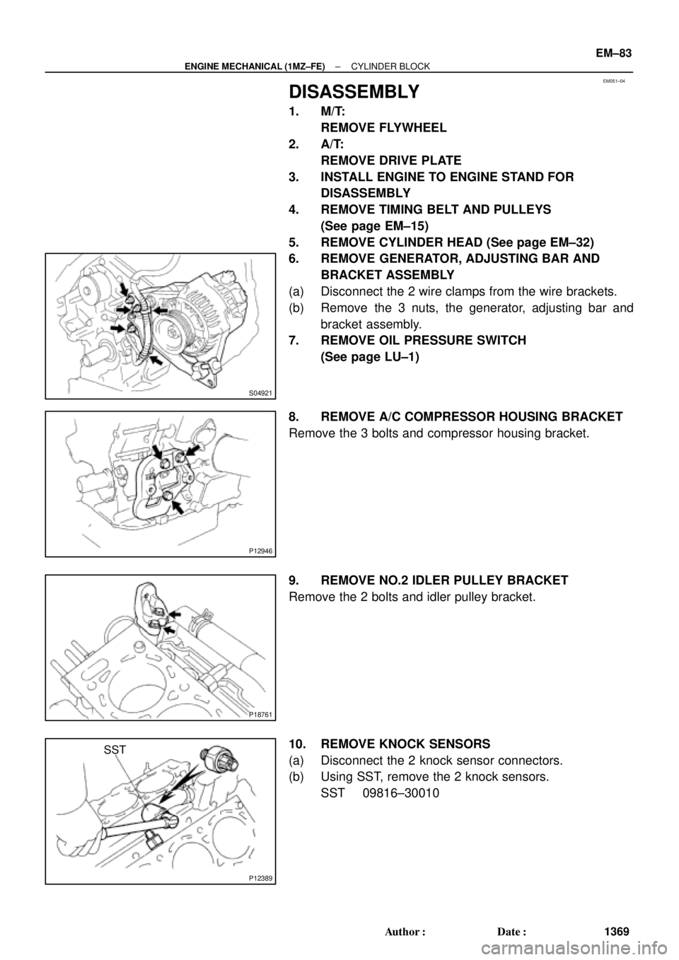
6. REMOVE GENERATOR, ADJUSTING BAR AND
BRACKET ASSEMBLY
(a) Disconnect the 2 wire clamps from the wire brackets.
(b) Remove the 3 nuts, the generator, adjusting bar and
bracket assembly.
7. REMOVE OIL PRESSURE SWITCH
(See page LU±1)
8. REMOVE A/C COMPRESSOR HOUSING BRACKET
Remove the 3 bolts and compressor housing bracket.
9. REMOVE NO.2 IDLER PULLEY BRACKET
Remove the 2 bolts and idler pulley bracket.
10. REMOVE KNOCK SENSORS
(a) Disconnect the 2 knock sensor connectors.
(b) Using SST, remove the 2 knock sensors.
SST 09816±30010
Page 3616 of 4770
P00601
Adhesive
A05416
1
2 34 5
67
8
EM±110
± ENGINE MECHANICAL (1MZ±FE)CYLINDER BLOCK
1396 Author�: Date�:
30. INSTALL OIL PRESSURE SWITCH
(See page LU±1)
31. INSTALL GENERATOR, BRACKET AND
ADJUSTING BAR ASSEMBLY
Torque: 43 N´m (440 kgf´cm, 32 ft´lbf)
32. INSTALL CYLINDER HEAD (See page EM±57)
33. INSTALL TIMING PULLEYS AND BELT
(See page EM±21)
34. REMOVE ENGINE STAND
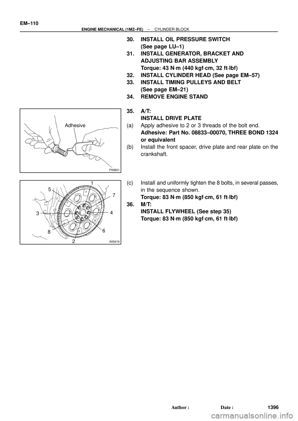
35. A/T:
INSTALL DRIVE PLATE
(a) Apply adhesive to 2 or 3 threads of the bolt end.
Adhesive: Part No. 08833±00070, THREE BOND 1324
or equivalent
(b) Install the front spacer, drive plate and rear plate on the
crankshaft.
(c) Install and uniformly tighten the 8 bolts, in several passes,
in the sequence shown.
Torque: 83 N´m (850 kgf´cm, 61 ft´lbf)
36. M/T:
INSTALL FLYWHEEL (See step 35)
Torque: 83 N´m (850 kgf´cm, 61 ft´lbf)
Page 3622 of 4770
BO0L2±01
H01975
Door Lock
Cylinder
Outside Handle Front Door Belt Moulding
Door Glass
Door FrameFront Door Upper Moulding
Outside
Rear View
Mirror
Door Glass
Run
5.5 (55, 49 in.´lbf)
5.5 (55, 49 in.´lbf)
5.0 (50, 43 in.´lbf)�
Door Lock
23 (230, 17)
Window Regulator
8.0 (80, 69 in.´lbf)
Door Hinge
X6
7.5 (75, 66 in.´lbf)
Regulator
Motor
X3
31 (310, 22)
26 (260, 19)
8.0 (80, 71 in.´lbf)
30 (300, 22)
31 (310, 22)
Door
Check
Door Hinge
26 (260, 19)
Speaker
Power Window Switch Rear Lower
FrameFront Lower
FrameFront Window Upper
Garnish
Inside Handle Bezel
3.5 (35, 31 in.´lbf)
Driver's Side:
Regulator
Motor
Ptdt
N´m (kgf´cm, ft´lbf) : Specified torqueInside Handle
Door Trim
� Precoated part Door Lock StrikerService Hole Cover BO±12
± BODYFRONT DOOR
2370 Author�: Date�:
2001 CAMRY (RM819U)
FRONT DOOR
COMPONENTS
Page 3624 of 4770
N20970
(a)
(b)(b)
N21004
Clip
H01729
: 7 rivets
: clip
: clip
: clip BO±14
± BODYFRONT DOOR
2372 Author�: Date�:
2001 CAMRY (RM819U)
8. REMOVE DOOR GLASS
(a) Open the door glass until the bolt appears in the service
hole.
(b) Remove the 2 bolts and the door glass.
HINT:
Pull the glass upward.
Torque: 8.0 N´m (80 kgf´cm, 71 in.´lbf)
9. REMOVE GLASS RUN
HINT:
Pull the glass run upward.
10. REMOVE FRONT AND REAR SIDE FRAMES
Remove the 2 bolts, 2 nuts and the side frames.
HINT:
Remove the side frames through the service hole.
11. REMOVE FRONT DOOR BELT MOULDING
Pry the rearward end of the front door belt moulding from the
door and remove the moulding.
12. REMOVE FRONT DOOR UPPER MOULDING
(a) Using a drill, cut the flange portion of the 7 rivets.
HINT:
At the time of assembly, please refer to the following item.
Use 7 new rivets.
(b) Pry out the 2 clips and remove the moulding.
Page 3627 of 4770
BO0L6±01
H01733
Door LockRear Door Upper
Moulding
Door Belt Moulding
Door Glass
Outside handle
Door Glass Run
Door Lock
Door Lock Striker
Rear Side Frame
Rear Door WeatherstripWindow Regulator
Inside Handle BezelInside HandleWindow
Regulator
Motor Child Protector
Lock Lever Cover
Snap Ring
Regulator
Handle Plate Door Trim Service Hole Cover Power Window
Switch Cover Door HingeDoor Hinge
Door Check w/o Power Door
Lock:
w/o Power Window:
: Specified torque
N´m (kgf´cm, ft´lbf)
3.5 (35, 31 in.´lbf)
5.5 (55, 49 in.´lbf)
5.5 (55, 49 in.´lbf)
23 (230, 17)
7.0 (70, 61 in.´lbf)
Door Lock Control Link
Door Lock Remote
Control Link
5.0 (50, 43 in.´lbf)
8.0 (80, 71 in.´lbf)
26 (260, 19)
8.0 (80, 71 in.´lbf)
30 (300, 22)
26 (260, 19)
BO±18
± BODYREAR DOOR
2376 Author�: Date�:
2001 CAMRY (RM819U)
REAR DOOR
COMPONENTS

5.5 (55, 49 in")