Page 4292 of 4770

SR06C±01
SR±2
± STEERINGTROUBLESHOOTING
2097 Author�: Date�:
TROUBLESHOOTING
PROBLEM SYMPTOMS TABLE
Use the table below to help you find the cause of the problem. The numbers indicate the priority of the likely
cause of the problem. Check each part in the order shown. If necessary, repair or replace these parts.
SymptomSuspect AreaSee page
Hard steering
1. Tires (Improperly inflated)
2. Power steering fluid level (Low)
3. Drive belt (Loose)
4. Front wheel alignment (Incorrect)
5. Steering system joints (Worn)
6. Suspension arm ball joints (Worn)
7. Steering column (Binding)
8. Power steering vane pump
9. Power steering gearSA±2
SR±5
SR±3
SA±4
±
SA±45
±
SR±18
SR±31
Poor return
1. Tires (Improperly inflated)
2. Front wheel alignment (Incorrect)
3. Steering column (Binding)
4. Power steering gearSA±2
SA±4
±
SR±31
Excessive play
1. Steering system joints (Worn)
2. Suspension arm ball joints (Worn)
3. Intermediate shaft, Sliding yoke (Worn)
4. Front wheel bearing (Worn)
5. Power steering gear±
SA±45
±
SA±10
SR±31
Abnormal noise
1. Power steering fluid level (Low)
2. Steering system joints (Worn)
3. Power steering vane pump
4. Power steering gearSR±5
±
SR±18
SR±31
Page 4293 of 4770
 Visually check the belt for excessive w")
P06717
SR06D±01
Z00038
DENSO Borroughs
P06723
CORRECT WRONG WRONG
± STEERINGDRIVE BELT
SR±3
2098 Author�: Date�:
DRIVE BELT
INSPECTION
INSPECT DRIVE BELT
(a) Visually check the belt for excessive wear, frayed cords
etc.
If any defect has been found, replace the drive belt.
HINT:
Cracks on the rib side of a belt are considered acceptable. If the
belt has chunks missing from the ribs, it should be replaced.
(b) Using a belt tension gauge, measure the belt tension.
Belt tension gauge:
DENSO BTG±20 (95506±00020)
Borroughs No. BT±33±73F
5S±FE Engine:
Drive belt tension:
New belt: 95 ± 145 lbf
Used belt: 60 ± 100 lbf
1MZ±FE Engine:
Drive belt tension:
New belt: 150 ± 185 lbf
Used belt: 95 ± 135 lbf
If the belt tension is not as specified, adjust it.
HINT:
�ºNew beltº refers to a belt which has been used less than
5 minutes on a running engine.
�ºUsed beltº refers to a belt which has been used on a run-
ning engine for 5 minutes or more.
�After installing a belt, check that it fits properly in the
ribbed grooves.
�Check with your hand to confirm that the belt has not
slipped out of the groove on the bottom of the pulley.
�After installing a new belt, run the engine for about 5 min-
utes and recheck the belt tension.
Page 4308 of 4770
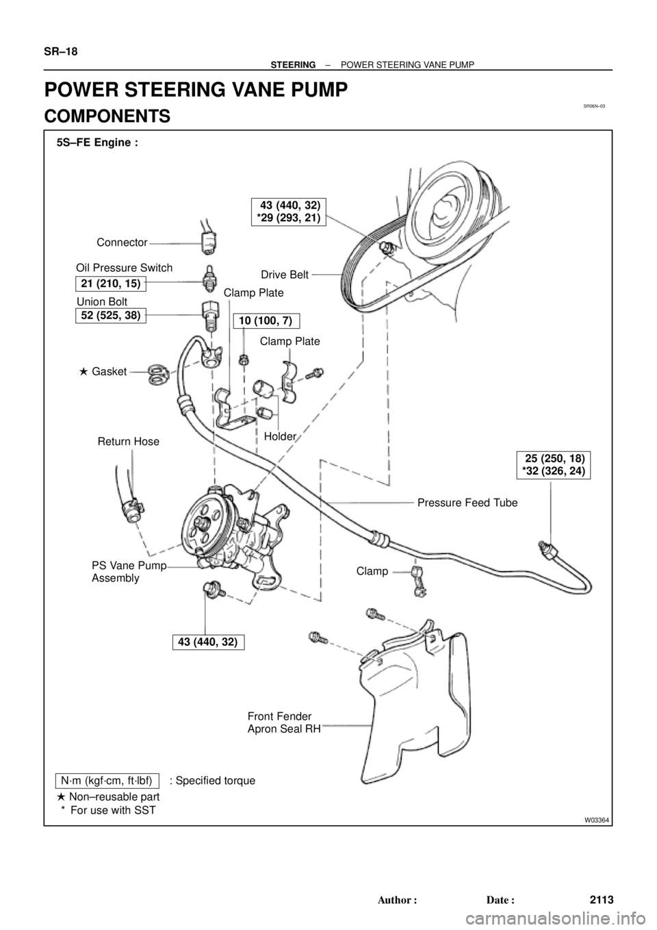
SR06N±03
W03364
Pressure Feed Tube Connector
Oil Pressure Switch
Drive Belt
Clamp Plate
Clamp Plate
Holder
Clamp
Front Fender
Apron Seal RH PS Vane Pump
AssemblyReturn Hose � Gasket Union Bolt 5S±FE Engine :
21 (210, 15)
43 (440, 32)
*29 (293, 21)
10 (100, 7)
25 (250, 18)
*32 (326, 24)
43 (440, 32)
52 (525, 38)
N´m (kgf´cm, ft´lbf) : Specified torque
� Non±reusable part
For use with SST * SR±18
± STEERINGPOWER STEERING VANE PUMP
2113 Author�: Date�:
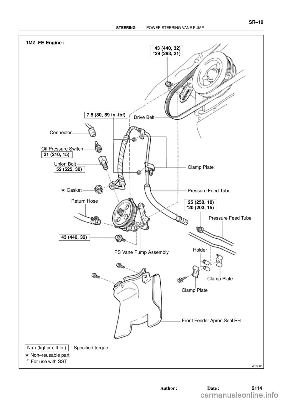
POWER STEERING VANE PUMP
COMPONENTS
Page 4309 of 4770
W03365
Drive Belt
Clamp Plate
Pressure Feed Tube
Pressure Feed Tube
Clamp Plate
Clamp Plate
Front Fender Apron Seal RH
N´m (kgf´cm, ft´lbf)
� Non±reusable part
For use with SST: Specified torquePS Vane Pump Assembly Return Hose � Gasket Union Bolt Connector
Oil Pressure Switch
43 (440, 32)
52 (525, 38)
21 (210, 15)
7.8 (80, 69 in.´lbf)
25 (250, 18)
*20 (203, 15)
43 (440, 32)
*29 (293, 21) 1MZ±FE Engine :
Holder
*
± STEERINGPOWER STEERING VANE PUMP
SR±19
2114 Author�: Date�:
Page 4311 of 4770

SR06O±01
W04220
5S±FE Engine :
1MZ±FE Engine :
Pressure
Feed TubeSST SST
W03360
Example 5S±FE Engine :
A
B
± STEERINGPOWER STEERING VANE PUMP
SR±21
2116 Author�: Date�:
REMOVAL
1. REMOVE FRONT FENDER APRON SEAL RH
Remove the 2 bolts.
2. DISCONNECT RETURN HOSE
NOTICE:
Take care not to spill fluid on the drive belt.
3. DISCONNECT PRESSURE FEED TUBE
(a) 5S±FE Engine:
Remove the clamp plate set bolt and nut.
(b) 5S±FE Engine:
Remove the 2 clamp plates and 2 holders from the tube.
(c) 5S±FE Engine:
Remove the clamp from the tube.
(d) 1MZ±FE Engine:
Remove the 2 clamp plate set nuts.
(e) 1MZ±FE Engine:
Remove the bolt.
(f) 1MZ±FE Engine:
Remove the 2 clamp plates and 2 holders from the tube.
(g) 5S±FE and 1MZ±FE Engines:
Using SST, disconnect the tube.
SST 09631±22020
4. REMOVE DRIVE BELT
Loosen the 2 (A and B) bolts.
5. REMOVE PS VANE PUMP ASSEMBLY WITH PRES-
SURE FEED TUBE
(a) Disconnect the connector from the oil pressure switch.
(b) Loosen bolt A sufficiently so that pump assembly can be
removed.
HINT:
Bolt A cannot be removed.
6. REMOVE PRESSURE FEED TUBE
(a) Remove the oil pressure switch from the union bolt.
NOTICE:
Be careful not to drop the switch.
If the switch is dropped or strongly damaged, replace it with a
new one.
(b) Remove the union bolt and gasket.
Page 4318 of 4770
SR06S±01
W03361
5S±FE Engine :
1MZ±FE Engine :Pressure Feed Tube
Stopper
Pressure
Feed
StopperTube
W03360
Example 5S±FE Engine :
A
B
W03542
5S±FE Engine :
SST
Fulcrum
Length SR±28
± STEERINGPOWER STEERING VANE PUMP
2123 Author�: Date�:
INSTALLATION
1. INSTALL PRESSURE FEED TUBE
(a) Torque the union bolt with a new gasket.
HINT:
Make sure the stopper of the tube is touching the front bracket,
as shown, then torque the union bolt.
5S±FE and 1MZ±FE Engines:
Torque: 52 N´m (525 kgf´cm, 38 ft´lbf)
(b) Install the oil pressure switch to the union bolt.
5S±FE and 1MZ±FE Engines:
Torque: 21 N´m (210 kgf´cm, 15 ft´lbf)
2. INSTALL PS VANE PUMP ASSEMBLY WITH PRESS-
ER FEED TUBE
Temporarily tighten the 2 (A and B) bolts.
3. INSTALL DRIVE BELT
(a) Adjust drive belt tension.
(See page SR±3)
(b) 5S±FE Engine:
Using SST, torque the A bolt.
SST 09249±63010
Torque: 29 N´m (293 kgf´cm, 21 ft´lbf)
HINT:
Use a torque wrench with a fulcrum length of 300 mm (11.81
in.).
Page 4436 of 4770

Toyota Supports ASE CertificationPage 1 of 7
BO002±00
Title:
SEAT BELT EXTENDER
Models:
'98 ± '00 Model Year
Technical Service
BULLETIN
January 21, 2000
Toyota customers who find it necessary to
increase the length of their seat belts may
obtain Seat Belt Extenders at no cost
through their local Toyota dealer.
�The extender is available in 6 inch, 9 inch,
12 inch, 15 inch and 18 inch lengths.
�The extender is available only in black.
�Owners are informed of the seat belt
extender availability through the Toyota
Owner 's Manual included in each vehicle.
The customer
(individual requiring the extender) must visit a Toyota dealership to have
the required measurements made and to complete the seat belt extender worksheet.
The worksheet will allow the proper fitting and selection of a seat belt extender for the
customer. The dealership personnel should then determine the applicable part number
and place a
Critical Order through the TDN Parts Network.
The dealership service department should complete the affixed Seat Belt Extender Label
and review the ªowner instruction sheetº with the customer. The dealership should give a
copy of the completed worksheet to the customer and keep the original in the customer's
file.
To assure utmost owner satisfaction, it is recommended that a dealership designate one
person to coordinate all activities related to the seat belt extender issue.
From past sales history, it is recommended that dealerships do not
stock Seat belt
extenders due to low demand and the need for customer fitting.
This bulletin contains the following information:
Procedure and Sample Label.................Page 2
Application Charts .................................Page 3±4
Part Number Information........................Page 5
Owner Instructions..................................Page 6
Seat Belt Extender Worksheet............... Page 7
�All Toyota models, 1998 through 2000 model years.
OP CODEDESCRIPTIONTIMEOPNT1T2
N/ANot Applicable to Warranty ±±±±
BODY
Introduction
Extender Seat Belt
Applicable
Vehicles
Warranty
Information
Page 4437 of 4770

SEAT BELT EXTENDER: '98 ± '00 ± BO002±00 January 21, 2000
Page 2 of 7
1. Owner requests a seat belt extender from dealer.
2. Dealer verifies the need for a seat belt extender and obtains a current copy of this
TSB and copies the worksheet.
3. Dealer measures the customer and completes the worksheet. Dealer determines the
correct part number and places a Critical Order for the part through the TDN Parts
Network.
4. Dealer receives seat belt extender and calls the customer in to check fit of the part.
5. If the seat belt extender fit is good, dealership personnel completes the customer
information label on the part, explains usage of the part, and gives the customer a
copy of the completed worksheet.
6. Dealer places a copy of the completed worksheet in the customer's records.
DEALER
MEASURE
CUSTOMER
&
COMPLETE
WORKSHEET
PLACE
CRITICAL
ORDER
THROUGH
TDNSHIP SEAT
BELT
EXTENDER
TO
DEALERTEST FIT
CUSTOMER
WITH PARTCOMPLETE
LABEL AND
ADVISE
OWNERRECEIVE
COPY OF
WORKSHEET
& USE
EXTENDER
FILE
WORKSHEET
IN
CUSTOMER
RECORDS
PARTS
SUPPLYDEALEROWNER
CAUTION
Procedure
Sample Seat
Belt Extender
Customer
Information
Label