Page 3429 of 4770
CYLINDER HEAD
EM±37
1209 Author�: Date�:
NOTICE:
�Support the timing belt, so the meshing of the crank-
shaft timing pulley and")
A02593
S05933
P03355
10 ± 45°
Knock
Pin
± ENGINE MECHANICAL (5S±FE)CYLINDER HEAD
EM±37
1209 Author�: Date�:
NOTICE:
�Support the timing belt, so the meshing of the crank-
shaft timing pulley and timing belt does not shift.
�Be careful not to drop anything inside the timing belt
cover.
�Do not allow the belt to come into contact with oil, wa-
ter or dust.
21. REMOVE ENGINE HANGERS AND GENERATOR
BRACKET
(a) Remove the 3 bolts, the generator bracket and RH engine
hanger assembly.
(b) Remove the bolt and LH engine hanger.
22. REMOVE OIL PRESSURE SWITCH
23. REMOVE CYLINDER HEAD COVER
Remove the 4 nuts, grommets, head cover and gasket.
HINT:
Arrange the grommets in the correct order, so that they can be
reinstalled into their original positions. This minimizes any pos-
sibility of oil leakage due to reuse of the grommets in different
positions.
24. REMOVE CAMSHAFTS
NOTICE:
Since the thrust clearance of the camshaft is small, the
camshaft must be kept level while it is being removed. If the
camshaft is not kept level, the portion of the cylinder head
receiving the shaft thrust may crack or be damaged, caus-
ing the camshaft to seize or break. To avoid this, the follow-
ing steps should be carried out.
(a) Remove the exhaust camshaft.
(1) Set the knock pin of the intake camshaft at 10 ± 45°
BTDC of camshaft angle.
HINT:
The above angle allows No.2 and No.4 cylinder cam lobes of
the exhaust camshaft to push their valve lifters evenly.
Page 3450 of 4770
CYLINDER HEAD
1230 Author�: Date�:")
P13638
Adhesive
S05962
Z09141
California
Except California New O±RingNew Insulator
New GrommetNew O±Ring
New GrommetNew
O±Ring EM±58
± ENGINE MECHANICAL (5S±FE)CYLINDER HEAD
1230 Author�: Date�:
9. INSTALL OIL PRESSURE SWITCH
(a) Apply adhesive to 2 or 3 threads.
Adhesive:
Part No. 08833±00080, THREE BOND 1324 or equiva-
lent
(b) Install the oil pressure switch.
10. INSTALL ENGINE HANGERS AND GENERATOR
BRACKET
(a) Install the generator bracket and RH engine hanger as-
sembly with the 3 bolts.
Torque: 42 N´m (425 kgf´cm, 31 ft´lbf)
(b) Install the LH engine hanger with the bolt.
Torque: 25 N´m (250 kgf´cm, 18 ft´lbf)
11. INSTALL NO.3 TIMING BELT COVER
Install the timing belt cover with the 3 bolts.
Torque: 7.8 N´m (80 kgf´cm, 69 in.´lbf)
12. TEMPORARILY INSTALL NO.1 IDLER PULLEY AND
TENSION SPRING (See page EM±23)
13. INSTALL CAMSHAFT TIMING PULLEY
(See page EM±23)
14. CONNECT TIMING BELT TO CAMSHAFT TIMING
PULLEY (See page EM±23)
15. INSTALL INJECTORS AND DELIVERY PIPE
(a) California:
Install a new insulator and grommet to each injector.
(b) Except California:
Install a new grommet to each injector.
(c) California:
Apply a light coat of gasoline onto 2 new O±rings, and
install them to each injector.
(d) Except California:
Apply a light coat of gasoline onto a new O±ring, and
install it to each injector.
Page 3453 of 4770
(c)(d)
± ENGINE MECHANICAL (5S±FE)CYLINDER HEAD
EM±61
1233 Author�: Date�:
18. CONNECT FUEL INLET HOSE TO DELIVERY PIPE
(a) T")
S05982
SST
Fulcrum
Length
A07365
A07363
A07364
Clamp
Connector
A01564(b)(c)(d)
± ENGINE MECHANICAL (5S±FE)CYLINDER HEAD
EM±61
1233 Author�: Date�:
18. CONNECT FUEL INLET HOSE TO DELIVERY PIPE
(a) Temporarily connect the fuel inlet hose with 2 new gas-
kets and fuel pulsation damper.
(b) Using SST, tighten the fuel pulsation damper.
SST 09612±24014 (09617±24011)
Torque:
34 N´m (350 kgf´cm, 25 ft´lbf)
29 N´m (300 kgf´cm, 21 ft´lbf) for use with SST
HINT:
Use a torque wrench with a fulcrum length of 30 cm (1.181 in.).
19. INSTALL ENGINE WIRE
(a) Install the 2 engine wire clamps to the 2 brackets on the
front side of the intake manifold.
(b) Install the engine wire clamp to the bracket on the LH side
of the intake manifold.
20. INSTALL EGR VALVE AND VACUUM MODULATOR
(a) Install a new gasket, the EGR valve, EGR pipe and vacu-
um modulator assembly with the union nut, 2 nuts and
bolt.
Torque:
13.3 N´m (136 kgf´cm, 10 ft´lbf) for nut
61.2 N´m (624 kgf´cm, 45 ft´lbf) for union nut
(b) Install the hose clamp to the bracket on the intake man-
ifold.
(c) Install the VSV for the EGR with the bolt.
(d) Connect the VSV connector for the EGR.
21. INSTALL INTAKE MANIFOLD STAY
Install the intake manifold stay with the bolt and nut.
Torque: 39 N´m (398 kgf´cm, 29 ft´lbf)
22. INSTALL WATER OUTLET
(a) Install a new gasket and the water outlet with the 2 nuts.
Torque: 15 N´m (150 kgf´cm, 11 ft´lbf)
(b) Connect the radiator hose to the water outlet.
(c) Connect the water bypass pipe hose to the water outlet.
(d) Connect the heater water hose to the water outlet.
(e) Connect the ECT sensor connector.
(f) Connect the ECT sender gauge connector.
23. CONNECT OIL PRESSURE SWITCH CONNECTOR
24. CONNECT NOISE FILTER CONNECTOR
Page 3456 of 4770

EM0YV±01
A02195
Radiator Reservoir Hose
Generator Drive BeltUpper Radiator
Hose
Support BracketFront Exhaust Pipe PS Oil Pressure Switch
ConnectorBattery TrayBattery
PS Pump Drive Belt
PS Pump
Support Stay Upper Radiator Support
Lower Radiator Hose
A/C Compressor
Cylinder Block Insulator
LH Front Fender Apron Seal
Oil Cooler Hose (A/T)
Cruise Control ActuatorEVAP Hose
Air Filter Upper Radiator
Support
EVAP Hose Hood
PCV Hose
Support
Bracket � Gasket
�
� Non±reusable part� Gasket
�Clamp
N´m (kgf´cm, ft´lbf)
62 (630, 46)
56 (570, 41)
�
: Specified torque
Washer Hose
for Windshield
No.1 Electric
Cooling Fan
Connector
ECT Switch
Connector No.2 Electric
Cooling Fan
ConnectorRadiator
Assembly
A/C Compressor
ConnectorLower Radiator
Support
RH Front Fender
Aplon Seal
Cruise
Control
Actuator
Connector
Battery
Hold±Down
ClampAir Cleaner
Case
VSV
Connector
for EVAP
EVAP
Hose
IAT Sensor
Connector
Air
Cleaner
Cap
EM±64
± ENGINE MECHANICAL (5S±FE)ENGINE UNIT
1236 Author�: Date�:
ENGINE UNIT
COMPONENTS
Page 3463 of 4770
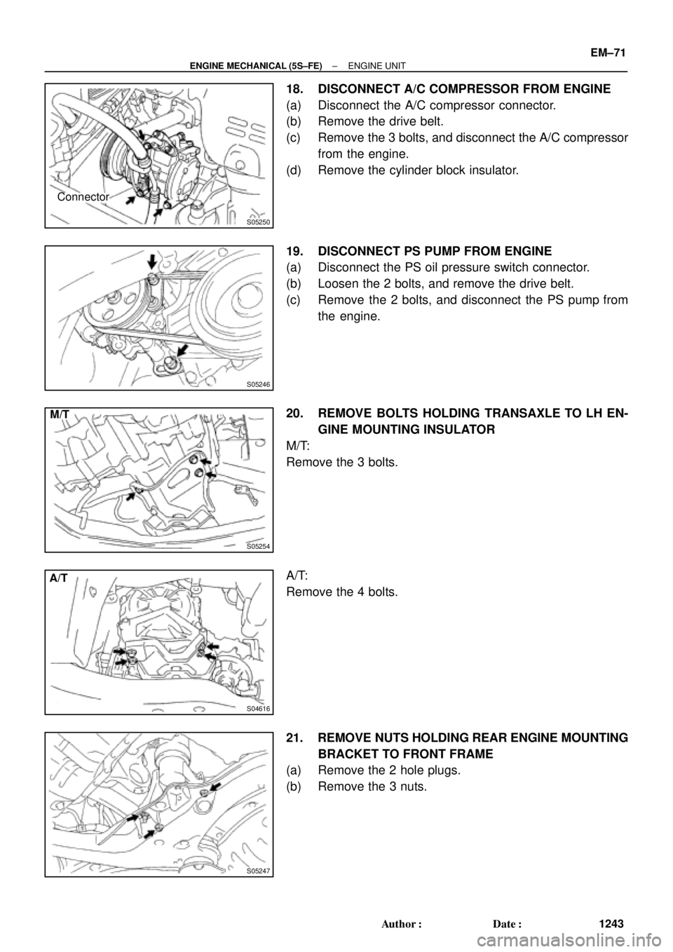
S05250
Connector
S05246
S05254
M/T
S04616
A/T
S05247
± ENGINE MECHANICAL (5S±FE)ENGINE UNIT
EM±71
1243 Author�: Date�:
18. DISCONNECT A/C COMPRESSOR FROM ENGINE
(a) Disconnect the A/C compressor connector.
(b) Remove the drive belt.
(c) Remove the 3 bolts, and disconnect the A/C compressor
from the engine.
(d) Remove the cylinder block insulator.
19. DISCONNECT PS PUMP FROM ENGINE
(a) Disconnect the PS oil pressure switch connector.
(b) Loosen the 2 bolts, and remove the drive belt.
(c) Remove the 2 bolts, and disconnect the PS pump from
the engine.
20. REMOVE BOLTS HOLDING TRANSAXLE TO LH EN-
GINE MOUNTING INSULATOR
M/T:
Remove the 3 bolts.
A/T:
Remove the 4 bolts.
21. REMOVE NUTS HOLDING REAR ENGINE MOUNTING
BRACKET TO FRONT FRAME
(a) Remove the 2 hole plugs.
(b) Remove the 3 nuts.
Page 3471 of 4770
ENGINE UNIT
EM±79
1251 Author�: Date�:
A/T:
Install the 4 bolts.
Torque: 64 N´m (650 kgf´cm, 47 ft´lbf)
24. REMOVE ENGINE SLI")
S04616
A/T
S05246
S05250
Connector
S05253
± ENGINE MECHANICAL (5S±FE)ENGINE UNIT
EM±79
1251 Author�: Date�:
A/T:
Install the 4 bolts.
Torque: 64 N´m (650 kgf´cm, 47 ft´lbf)
24. REMOVE ENGINE SLING DEVICE
25. CONNECT TRANSAXLE CONTROL CABLE(S) TO
TRANSAXLE
26. INSTALL PS PUMP
(a) Install the PS pump with the 2 bolts.
Torque: 43 N´m (440 kgf´cm, 32 ft´lbf)
(b) Install the drive belt.
(c) Connect the PS oil pressure switch connector.
27. INSTALL A/C COMPRESSOR
(a) Install the cylinder block insulator and A/C compressor
with the 3 bolts.
Torque: 25.5 N´m (260 kgf´cm, 19 ft´lbf)
(b) Install the drive belt.
(c) Connect the A/C compressor connector.
28. M/T:
INSTALL CLUTCH RELEASE CYLINDER AND TUBE
TO TRANSAXLE
29. M/T:
INSTALL STARTER (See page ST±19)
30. INSTALL DRIVE SHAFTS (See page SA±24)
31. CONNECT ENGINE WIRE TO CABIN
(a) Push in the engine wire through the cowl panel. Install the
grommet.
(b) Connect the 3 engine ECM connectors.
(c) Connect the 3 cowl wire connectors to the connectors on
the bracket.
(d) Install the under cover.
32. CONNECT CONNECTORS, WIRES, CABLES,
CLAMPS AND HOSES
(a) Connect the generator wire.
Page 3587 of 4770

No.2 Idler Pulley Bracket
Water Seal Plate
Engine Cool")
EM050±03
A06640
Knock Sensor Connector
Engine Wire Band
Engine WireKnock Sensor
No.2 ECT Switch Connector
Water Inlet Housing
(With Water Inlet)
No.2 Idler Pulley Bracket
Water Seal Plate
Engine Coolant
Drain Union
Oil Filter Union
Oil Filter � Gasket
EGR Cooler
� Gasket
Water Pump
� Crankshaft
Front Oil Seal
Crankshaft
Position Sensor
Connector� Oil Pressure Switch
Oil Pressure Switch
ConnectorA/C Compressor
Housing Bracket
No.1 Oil Pan
x 15 or 17 Oil Pump
� Gasket
� Gasket
Engine Wire
Generator
Drain Plugx 10No.2 Oil Pan Oil Strainer
� Non±reusable part
N´m (kgf´cm, ft´lbf) : Specified torque
Precoated part �
x 8
�
� O±Ring
x 9
9 (90, 78 in.´lbf)
8 (80, 69 in.´lbf)
10mm Head 7.8 (80, 69 in.´lbf)
12mm Head 19.5 (200,14)
39 (400, 29)
28 (290, 21)
14.5 (145, 10)
25 (250, 18)
10mm Head 8 (80, 69 in.´lbf)
12mm Head 19.5 (200,14)
8 (80, 69 in.´lbf)
8 (80, 69 in.´lbf)45 (460, 33)
8 (80, 69 in.´lbf)
or 0 or 0
± ENGINE MECHANICAL (1MZ±FE)CYLINDER BLOCK
EM±81
1367 Author�: Date�:
CYLINDER BLOCK
COMPONENTS
Page 3589 of 4770
EM051±04
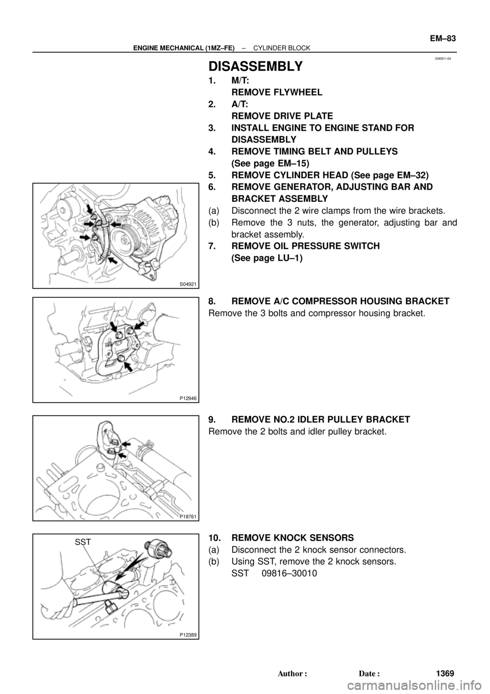
S04921
P12946
P18761
P12389
SST
± ENGINE MECHANICAL (1MZ±FE)CYLINDER BLOCK
EM±83
1369 Author�: Date�:
DISASSEMBLY
1. M/T:
REMOVE FLYWHEEL
2. A/T:
REMOVE DRIVE PLATE
3. INSTALL ENGINE TO ENGINE STAND FOR
DISASSEMBLY
4. REMOVE TIMING BELT AND PULLEYS
(See page EM±15)
5. REMOVE CYLINDER HEAD (See page EM±32)
6. REMOVE GENERATOR, ADJUSTING BAR AND
BRACKET ASSEMBLY
(a) Disconnect the 2 wire clamps from the wire brackets.
(b) Remove the 3 nuts, the generator, adjusting bar and
bracket assembly.
7. REMOVE OIL PRESSURE SWITCH
(See page LU±1)
8. REMOVE A/C COMPRESSOR HOUSING BRACKET
Remove the 3 bolts and compressor housing bracket.
9. REMOVE NO.2 IDLER PULLEY BRACKET
Remove the 2 bolts and idler pulley bracket.
10. REMOVE KNOCK SENSORS
(a) Disconnect the 2 knock sensor connectors.
(b) Using SST, remove the 2 knock sensors.
SST 09816±30010