Page 3616 of 4770
P00601
Adhesive
A05416
1
2 34 5
67
8
EM±110
± ENGINE MECHANICAL (1MZ±FE)CYLINDER BLOCK
1396 Author�: Date�:
30. INSTALL OIL PRESSURE SWITCH
(See page LU±1)
31. INSTALL GENERATOR, BRACKET AND
ADJUSTING BAR ASSEMBLY
Torque: 43 N´m (440 kgf´cm, 32 ft´lbf)
32. INSTALL CYLINDER HEAD (See page EM±57)
33. INSTALL TIMING PULLEYS AND BELT
(See page EM±21)
34. REMOVE ENGINE STAND
35. A/T:
INSTALL DRIVE PLATE
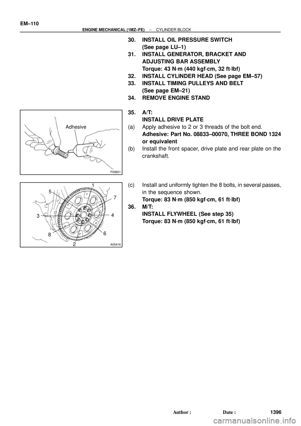
(a) Apply adhesive to 2 or 3 threads of the bolt end.
Adhesive: Part No. 08833±00070, THREE BOND 1324
or equivalent
(b) Install the front spacer, drive plate and rear plate on the
crankshaft.
(c) Install and uniformly tighten the 8 bolts, in several passes,
in the sequence shown.
Torque: 83 N´m (850 kgf´cm, 61 ft´lbf)
36. M/T:
INSTALL FLYWHEEL (See step 35)
Torque: 83 N´m (850 kgf´cm, 61 ft´lbf)
Page 3707 of 4770

IN04Q±03
IN±36
± INTRODUCTIONTERMS
36 Author�: Date�:
TERMS
ABBREVIATIONS USED IN THIS MANUAL
AbbreviationsMeaning
ABSAnti±Lock Brake System
ACAlternating Current
ACCAccessory
ACISAcoustic Control Induction System
ACSDAutomatic Cold Start Device
A.D.D.Automatic Disconnecting Differential
A/FAir±Fuel Ratio
AHCActive Height Control Suspension
ALRAutomatic Locking Retractor
ALTAlternator
AMPAmplifier
ANTAntenna
APPROX.Approximately
A/TAutomatic Transmission (Transaxle)
AT FAutomatic Transmission Fluid
AUTOAutomatic
AUXAuxiliary
AV GAverage
AV SAdaptive Variable Suspension
BACSBoost Altitude Compensation System
BATBattery
BDCBottom Dead Center
B/LBi±Level
B/SBore±Stroke Ratio
BTDCBefore Top Dead Center
BVSVBimetallic Vacuum Switching Valve
Calif.California
CBCircuit Breaker
CCoCatalytic Converter For Oxidation
CDCompact Disc
CFCornering Force
CGCenter Of Gravity
CHChannel
COMB.Combination
CPECoupe
CPSCombustion Pressure Sensor
CPUCentral Processing Unit
CRSChild Restraint System
CTRCenter
C/VCheck Valve
CVControl Valve
CWCurb Weight
Page 3715 of 4770
 :
TEMPERATURE RANGE ANTICIPATED BEFORE NEXT OIL CHANGE 10W ± 30
5W ± 30 PREFERRED
±20
°C °F020406080
±29 ±18 ±7 4 16 27100
38
LU03H±03
S05317
Curved
Tip
Ins")
B00319
Recommended Viscosity (SAE) :
TEMPERATURE RANGE ANTICIPATED BEFORE NEXT OIL CHANGE 10W ± 30
5W ± 30 PREFERRED
±20
°C °F020406080
±29 ±18 ±7 4 16 27100
38
LU03H±03
S05317
Curved
Tip
Insert
S05298
Oil Pressure Gauge
P13638
Adhesive
± LUBRICATION (5S±FE)OIL AND FILTER
LU±1
1647 Author�: Date�:
OIL AND FILTER
INSPECTION
1. CHECK ENGINE OIL QUALITY
Check the oil for deterioration, entry of water, discoloring or thin-
ning.
If the quality is visibly poor, replace the oil.
Oil grade:
API grade SJ, Energy±Conserving or ILSAC multi-
grade engine oil. SAE 5W±30 is the best choice for
your vehicle, for good fuel economy, and good start-
ing in cold weather.
2. CHECK ENGINE OIL LEVEL
After warming up the engine and then 5 minutes after the en-
gine stop, oil level should be between ºLº and ºFº of the dipstick.
If low, check for leakage and add oil up to ºFº mark.
NOTICE:
�Do not fill with engine oil above the ºFº mark.
�When inserting the oil dipstick, insert the curved tip
of the dipstick facing the same direction as the curve
of the guide.
�If the dipstick gets caught while inserting it, do not
force it in. Reconfirm the direction of the dipstick.
3. REMOVE OIL PRESSURE SWITCH AND INSTALL OIL
PRESSURE GAUGE
4. WARM UP ENGINE
Allow the engine to warm up to normal operating temperature.
5. CHECK OIL PRESSURE
Oil pressure:
At idle29 kPa (0.3 kgf/cm2, 4.3 psi) or more
At 3,000 rpm245 ± 490 kPa (2.5 ± 5.0 kgf/cm2, 36 ± 71 psi)
6. REMOVE OIL PRESSURE GAUGE AND REINSTALL
OIL PRESSURE SWITCH
(a) Remove the oil pressure gauge.
(b) Apply adhesive to 2 or 3 threads of the oil pressure switch.
Adhesive:
Part No. 08833±00080, THREE BOND 1344, LOCTITE
242 or equivalent
(c) Reinstall the oil pressure switch.
7. START ENGINE AND CHECK FOR OIL LEAKS
Page 3733 of 4770
:
TEMPERATURE RANGE ANTICIPATED BEFORE NEXT OIL CHANGE10W±30
5W±30 PREFERRED°C °F
±20
±290
±1820
±740
460
1680
27100
38
LU0FR±01
P25173SST
P25171
Oil Pressur")
B00319
Recommended Viscosity (SAE):
TEMPERATURE RANGE ANTICIPATED BEFORE NEXT OIL CHANGE10W±30
5W±30 PREFERRED°C °F
±20
±290
±1820
±740
460
1680
27100
38
LU0FR±01
P25173SST
P25171
Oil Pressure Gauge
± LUBRICATION (1MZ±FE)OIL AND FILTER
LU±1
1665 Author�: Date�:
OIL AND FILTER
INSPECTION
1. CHECK ENGINE OIL QUALITY
Check the oil for deterioration, entry of water, discoloring or thin-
ning.
If the quality is visibly poor, replace the oil.
Oil grade:
API grade SJ, Energy±Conserving or ILSAC multi-
grade engine oil.
SAE 5W ± 30 is the best choice for your vehicle, for
good fuel economy, and good starting in cold weath-
er.
2. CHECK ENGINE OIL LEVEL
After warm up the engine and then 5 minutes after the engine
stop, oil level should be between the low level and full level
marks on the dipstick.
If low, check for leakage and add oil up to the full level mark.
NOTICE:
Do not fill with engine oil above the full level mark.
3. REMOVE OIL PRESSURE SWITCH, AND INSTALL
OIL PRESSURE GAUGE
(a) Using SST, remove the oil pressure switch.
SST 09816±30010
(b) Install the oil pressure gauge.
4. WARM UP ENGINE
Allow the engine to warm up to normal operating temperature.
5. CHECK OIL PRESSURE
Oil pressure:
At idle29 kPa (0.3 kgf/cm2, 4.3 psi) or more
At 3,000 rpm294 ± 539 kPa (3.0 ± 5.5 kgf/cm2, 43 ± 78 psi)
Page 3734 of 4770
P12478
Adhesive
LU±2
± LUBRICATION (1MZ±FE)OIL AND FILTER
1666 Author�: Date�:
6. REMOVE OIL PRESSURE GAUGE AND REINSTALL
OIL PRESSURE SWITCH
(a) Remove the oil pressure gauge.
(b) Apply adhesive to 2 or 3 threads of the oil pressure switch.
Adhesive: Part No. 08833±00080, THREE BOND 1344,
LOCTITE 242 or equivalent
(c) Using SST, install the oil pressure switch.
SST 09816±30010
Torque: 13 N´m (130 kgf´cm, 9 ft´lbf)
7. START ENGINE AND CHECK FOR LEAKS
Page 3858 of 4770
PP1WA±02
± PREPARATIONENGINE MECHANICAL (5S±FE)
PP±7
59 Author�: Date�:
SSM (Special Service Materials)
08826±00080Seal Packing Black or equivalent
(FIPG)Camshaft bearing cap
Cylinder head cover
Semi±circular plug
08833±00070Adhesive 1324,
THREE BOND 1324 or equivalentFlywheel or drive plate bolt
Torque converter clutch bolt
08833±00080Adhesive 1344
THREE BOND 1344
LOCTITE 242 or equivalentOil pressure switch
Page 3860 of 4770
± PREPARATIONENGINE MECHANICAL (1MZ±FE)
PP±9
61 Author�: Date�:
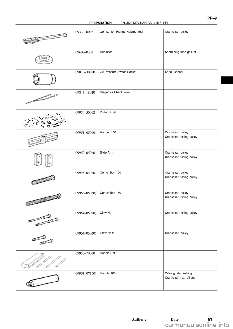
09330±00021Companion Flange Holding ToolCrankshaft pulley
09608±03071ReplacerSpark plug tube gasket
09816±30010Oil Pressure Switch SocketKnock sensor
09843±18020Diagnosis Check Wire
09950±50012Puller C Set
(09951±05010)Hanger 150Crankshaft pulley
Crankshaft timing pulley
(09952±05010)Slide ArmCrankshaft pulley
Crankshaft timing pulley
(09953±05010)Center Bolt 100Crankshaft pulley
Crankshaft timing pulley
(09953±05020)Center Bolt 150Crankshaft pulley
Crankshaft timing pulley
(09954±05010)Claw No.1Crankshaft timing pulley
(09954±05020)Claw No.2Crankshaft pulley
09950±70010Handle Set
(09951±07100)Handle 100Valve guide bushing
Crankshaft rear oil seal
Page 3868 of 4770
PP1WB±02
± PREPARATIONSFI (5S±FE)
PP±17
69 Author�: Date�:
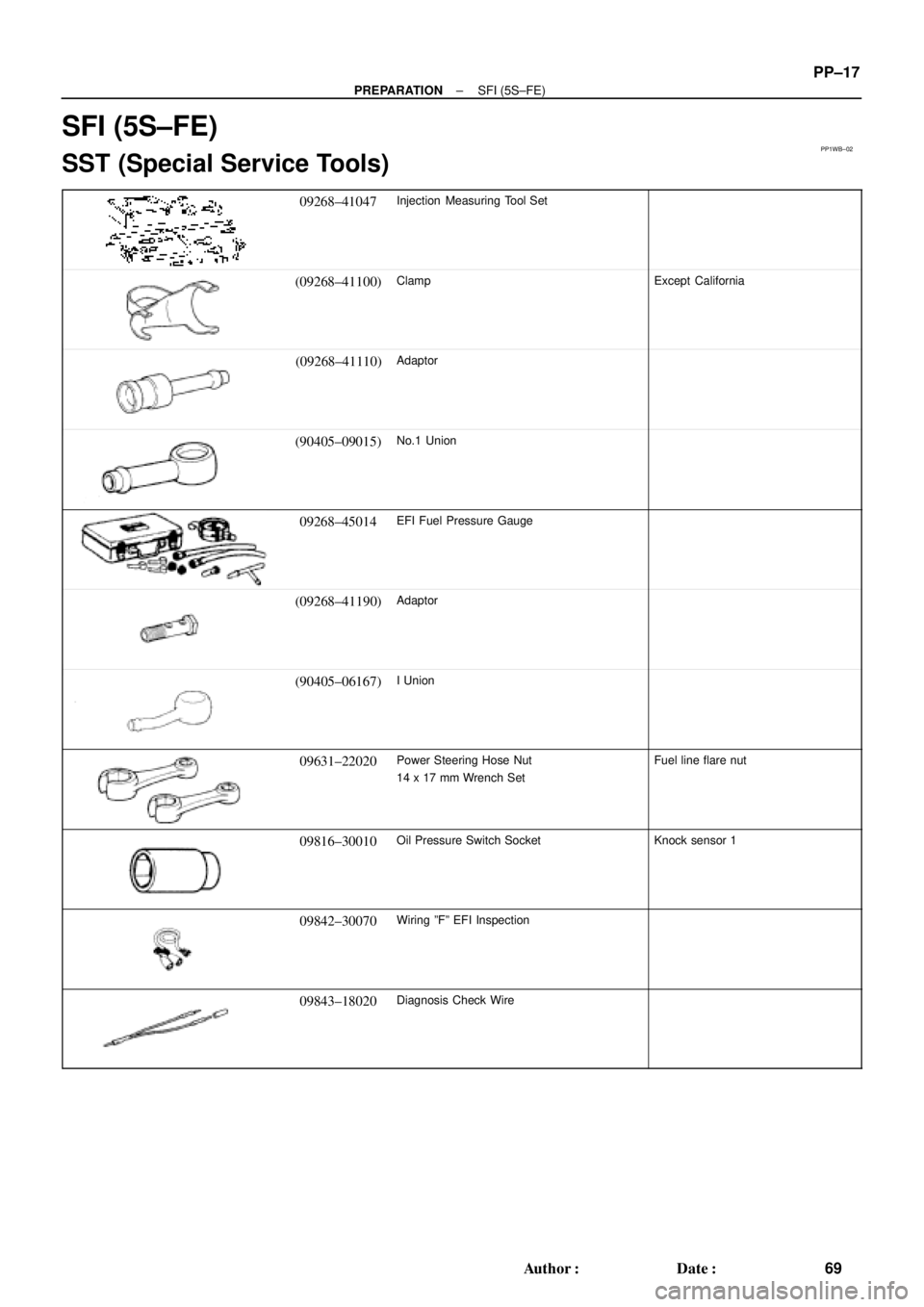
SFI (5S±FE)
SST (Special Service Tools)
09268±41047Injection Measuring Tool Set
(09268±41100)ClampExcept California
(09268±41110)Adaptor
(90405±09015)No.1 Union
09268±45014EFI Fuel Pressure Gauge
(09268±41190)Adaptor
(90405±06167)I Union
09631±22020Power Steering Hose Nut
14 x 17 mm Wrench SetFuel line flare nut
09816±30010Oil Pressure Switch SocketKnock sensor 1
09842±30070Wiring ºFº EFI Inspection
09843±18020Diagnosis Check Wire