Page 2745 of 4770
 PTNK (+)
EngineStart
Stop
OFF ON OFF VSV for
ON
Vapor
Pressure
Sensor
VSV for
EVAP
5 sec.
Measure Voltage
± DIAGNOSTICSENGINE (1MZ±FE)
DI±325
560 Author�: Date�:
14 Check vacuum hose")
A07147
E2 (±) PTNK (+)
EngineStart
Stop
OFF ON OFF VSV for
ON
Vapor
Pressure
Sensor
VSV for
EVAP
5 sec.
Measure Voltage
± DIAGNOSTICSENGINE (1MZ±FE)
DI±325
560 Author�: Date�:
14 Check vacuum hoses between charcoal canister and VSV for vapor pressure
sensor, and vapor pressure sensor and VSV for vapor pressure sensor.
CHECK:
(a) Check that the vacuum hose is connected correctly.
(b) Check the vacuum hose for looseness and disconnection.
(c) Check the vacuum hose for cracks, hole, damage and blockage.
NG Repair or replace.
OK
15 Check charcoal canister.
PREPARATION:
(a) Connect the TOYOTA hand±held tester to the DLC3.
(b) Remove the fuel tank cap.
(c) Disconnect the VSV connector for vapor pressure sensor.
(d) Select the ACTIVE TEST mode on the TOYOTA
hand±held tester.
(e) Start the engine.
(f) VSV for EVAP is ON by the TOYOTA hand±held tester
and remains on for 5 sec.
CHECK:
Measure voltage between terminals PTNK and E2 of ECM con-
nectors 5 sec. after switching VSV for EVAP from ON to OFF.
OK:
Voltage: 2.5 V or less
NG Replace charcoal canister.
OK
Page 2749 of 4770
A07149
ON
TPC
OFFON
VSV is ON
VSV is OFF
Air
E
FG Air
G E
F
± DIAGNOSTICSENGINE (1MZ±FE)
DI±329
564 Author�: Date�:
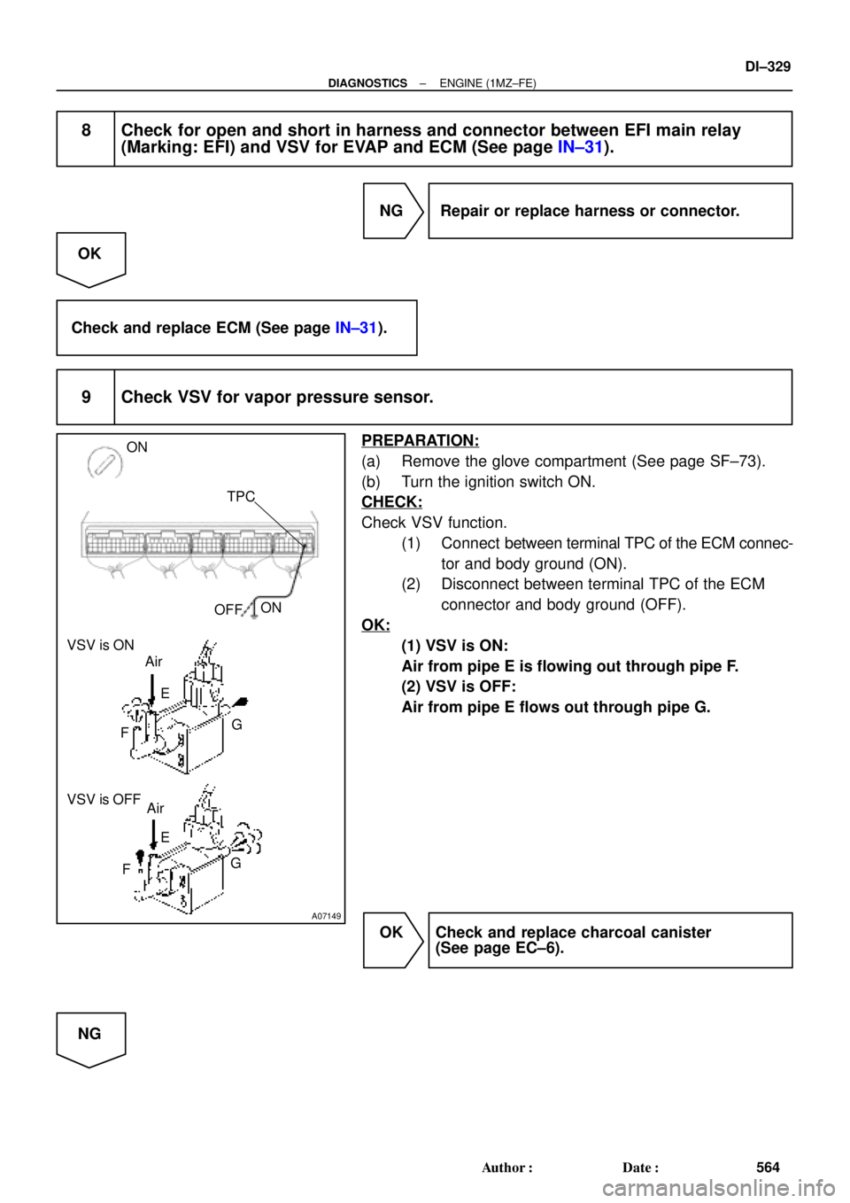
8 Check for open and short in harness and connector between EFI main relay
(Marking: EFI) and VSV for EVAP and ECM (See page IN±31).
NG Repair or replace harness or connector.
OK
Check and replace ECM (See page IN±31).
9 Check VSV for vapor pressure sensor.
PREPARATION:
(a) Remove the glove compartment (See page SF±73).
(b) Turn the ignition switch ON.
CHECK:
Check VSV function.
(1) Connect between terminal TPC of the ECM connec-
tor and body ground (ON).
(2) Disconnect between terminal TPC of the ECM
connector and body ground (OFF).
OK:
(1) VSV is ON:
Air from pipe E is flowing out through pipe F.
(2) VSV is OFF:
Air from pipe E flows out through pipe G.
OK Check and replace charcoal canister
(See page EC±6).
NG
Page 2869 of 4770

DI±449
684 Author�: Date�:
DIAGNOSTIC TROUBLE CODE CHART
If a DTC is displayed during the DTC check, check the circuit listed for that code in the")
DI02F±02
± DIAGNOSTICSAUTOMATIC TRANSAXLE (A541E)
DI±449
684 Author�: Date�:
DIAGNOSTIC TROUBLE CODE CHART
If a DTC is displayed during the DTC check, check the circuit listed for that code in the table below and pro-
ceed to the page given.
* : ±...MIL does not light /�...MIL light up
DTC No.
(See Page)Detection ItemTrouble AreaMIL *Memory
P0500
(DI±456)Vehicle Speed Sensor Malfunc-
tion
(No.1 Vehicle Speed Sensor)
�Open or short in No.1 vehicle speed sensor circuit
�No.1 vehicle speed sensor
�Combination meter
�ECM
�Automatic transaxle (clutch, brake or gear etc.)
��
P0750
(DI±460)Shift Solenoid A Malfunction
(Shift Solenoid Valve No.1)�Shift solenoid valve No.1 is stuck open or closed
�Valve body is blocked up or stuck
�Automatic transaxle (clutch, brake or gear etc.)
��
P0753
(DI±462)Shift Solenoid A Electrical Mal-
function
(Shift Solenoid Valve No.1)�Open or short in shift solenoid valve No.1 circuit
�Shift solenoid valve No.1
�ECM
��
P0755
(DI±460)Shift Solenoid B Malfunction
(Shift Solenoid Valve No.2)�Shift solenoid valve No.2 is stuck open or closed
�Valve body is blocked up or stuck
�Automatic transaxle (clutch, brake or gear etc.)
��
P0758
(DI±462)Shift Solenoid B Electrical Mal-
function
(Shift Solenoid Valve No.2)�Open or short in shift solenoid valve No.2 circuit
�Shift solenoid valve No.2
�ECM
��
P0770
(DI±466)Shift Solenoid E Malfunction
(Shift Solenoid Valve SL)
�Shift solenoid valve SL is stuck open or closed
�Valve body is blocked up or stuck
�Lock±up clutch
�Automatic transaxle (clutch, brake or gear etc.)
��
P0773
(DI±468)Shift Solenoid E Electrical Mal-
function
(Shift Solenoid Valve SL)�Open or short in shift solenoid valve SL circuit
�Shift solenoid valve SL
�ECM
��
P1520
(DI±472)Stop Light Switch Signal Mal-
function�Open or short in stop light switch circuit
�Stop light switch
�ECM
��
P1705
(DI±473)NC2 Revolution Sensor Circuit
Malfunction
(Direct Clutch Speed Sensor)�Open or short in direct clutch speed sensor circuit
�Direct clutch speed sensor
�ECM
��
P1765
(DI±476)
Linear Solenoid for Accumulator
Pressure Control Circuit Mal-
function
(Shift Solenoid Valve SLN)�Open or short in shift solenoid valve SLN circuit
�Shift solenoid valve SLN
�ECM
��
P1780
(DI±479)Park/Neutral Position Switch
Malfunction�Short in park/neutral position switch circuit
�Park/neutral position switch
�ECM
��
Page 2893 of 4770

Q04869
NC2 Revolution Sensor
D01094
Direct Clutch
Speed Sensor 2V3
1
V3
G R
E99
E94ECM
NC2
+
NC2±4 ~ 6 V
*1: Except California, w/ Engine Immobilizer and / or TRAC
*2: California, w/ Engine Immobilizer and / or TRAC*2 *1
E1114
26 *2 *1
E11
± DIAGNOSTICSAUTOMATIC TRANSAXLE (A541E)
DI±473
708 Author�: Date�:
DTC P1705 NC2 Revolution Sensor Circuit Malfunction
(Direct Clutch Speed Sensor)
CIRCUIT DESCRIPTION
This sensor detects the rotation speed of the direct clutch drum.
By comparing the direct clutch speed signal and the vehicle
speed sensor signal, the ECM detects the shift timing of the
gears and appropriately controls the engine torque and hydrau-
lic pressure in response to various conditions, thus performing
smooth gear shifting.
DTC No.DTC Detecting ConditionTrouble Area
P1705
The ECM detects conditions (a), (b), (c), (d), (e) and (f) conti-
nuity for 4 sec or more.
(2 trip detection logic)
(a) Vehicle speed : 32 km/h (20 mph) or more
(b) 3rd or 4th gear
(c) NC2 < 300 rpm
(d) Park/neutral position switch: OFF
(e) Solenoid valves and vehicle speed sensor are normal
(f) L position: OFF
�Open or short in direct clutch speed sensor circuit
�Direct clutch speed sensor
�ECM
WIRING DIAGRAM
DI02P±02
Page 2896 of 4770

High
Accumulator Control Pressure
D00060
(*) Duty Ratio
The duty ratio is the ratio of the period of continuity in one cycle.
For example, if A is the period of continu")
AT5608
0
1
Electric Current (A)
High
Accumulator Control Pressure
D00060
(*) Duty Ratio
The duty ratio is the ratio of the period of continuity in one cycle.
For example, if A is the period of continuity in one cycle, and B is the period of non±continuity, then
D000621 msec./div.5 V/div.
GND Reference
Waveform between terminals SLN
+
and SLN± when engine is idling.Waveform between terminals SLN
+
and SLN± when during shift change.
1 msec./div.5 V/div.
GND DI±476
± DIAGNOSTICSAUTOMATIC TRANSAXLE (A541E)
711 Author�: Date�:
DTC P1765Linear Solenoid for Accumulator Pressure Control
Circuit Malfunction (Shift Solenoid Valve SLN)
CIRCUIT DESCRIPTION
The shift solenoid valve SLN controls the hydraulic pressure
acting on the accumulator control valve when gears are shifted
and performs smooth gear shifting.
The ECM determines optimum operating pressure according to
the signals from the throttle position sensor, vehicle speed sen-
sor and direct clutch speed sensor and controls the volume of
current flow to the solenoid valve.
The amount of current to the solenoid is controlled by the (*)
duty ratio of ECM output signals, causing a momentary change
to the hydraulic pressure acting on the clutches during gear
shifting.
When the duty ratio is high, the hydraulic pressure acting on the
clutches is low.
DTC No.DTC Detecting ConditionTrouble Area
P1765
After the engine is warmed up, the current flow to the shift
solenoid valve SLN for 1 sec or more under condition (a) or
(b):
(a) Engine speed: 500 rpm or more
(b) Park/neutral position switch: ON (P or N position)
�Open or short in shift solenoid valve SLN circuit
�Shift solenoid valve SLN
�ECM
DI02Q±02
Page 3422 of 4770

A01562
Generator Wire
Generator
Connector
GeneratorWire Clamp
Wire
Clamp
ECT Sender
Gauge ConnectorThrottle BodyThrottle Position
Sensor ConnectorIgnition Coil Connector
IAC Valve
Connector
Heater Water Hose
Radiator Hose ECT Sensor
Connector
Water Outlet
Noise Filter Connector
Oil Pressure Switch Connector
Ignition Coil and No.2 Intake
Manifold Assembly
(with High±Tension Cord)
A/F Sensor Connector (California) or
Heated Oxygen Sensor (Bank 1 Sensor 1)
Connector (Except California)
(TMMK Made) � Gasket� Gasket � Gasket
(TMC Made)No.1 Exhaust
Manifold Stay
No.2 Exhaust
Manifold Stay No.1 Exhaust
Manifold Heat
Insulator
Exhaust Manifold,
No.2 and No.3
Exhaust Manifold
Heat Insulator
Assembly
� Non±reusable partExcept California
19 (195, 14)
49 (500, 36)
49 (500, 36)
: Specified torqueN´m (kgf´cm, ft´lbf)x 6
Exhaust Manifold,
No.2 and no.3
Exhaust Manifold
Heat Insulator
Assenbly
(California)
No.1 Exhaust
Manifold Heat
Insulator (California) (TMMK Made)
(TMC Made)
EM±30
± ENGINE MECHANICAL (5S±FE)CYLINDER HEAD
1202 Author�: Date�:
Page 3424 of 4770

A07368
Spark Plug
Grommet
Cylinder Head Cover
Gasket
Camshaft Bearing Cap
� Camshaft Oil Seal
Camshaft Timing Pulley
Snap Ring
Wave Washer
Camshaft Position Sensor Connector
Camshaft Position Sensor Assembly
Wire Clamp
No. 3 Timing Belt Cover
No.2 Timing Belt Cover� Oil Seal
Valve Guide
Bushing
Cylinder
Head
Gasket Adjusting Shim
Valve Lifter
Keeper
Spring Retainer
Valve Spring
Spring Seat
Valve
LH Engine
Hanger
Semi±Circular
Plug
Oil Pressure
Switch
Camshaft Gear Spring
Camshaft Sub±Gear
Semi±Circular
Plug
Tension Spring
No.1 Idler Pulley
*
1
GasketTiming Belt
Cylinder Head Intake
CamshaftExhaust
Camshaft
Wire
Clamp
Wire
Clamp
Generator Bracket and
RH Engine Hanger
Assembly
N´m (kgf´cm, ft´lbf)
*
2 For use with SST
� Non±reusable part
18 (180, 13)
44 (450, 33)
19 (190, 14)
*
237 (380, 27)1st 49 (500, 36)
2nd Turn 90°
42 (425, 31)
x 10�
�
: Specified torque
See page EM±53
*1
Replace only if damaged
54 (550, 40)
EM±32
± ENGINE MECHANICAL (5S±FE)CYLINDER HEAD
1204 Author�: Date�:
Page 3426 of 4770
(d)
(e)
A07364
ConnectorClamp
EM±34
± ENGINE MECHANICAL (5S±FE)CYLINDER HEAD
1206 Author�: Date�:
(j) California:
Disconnect the A/F sensor connector for the wiring side")
S05548
Wire
Clamp
A01564(c)(d)
(e)
A07364
ConnectorClamp
EM±34
± ENGINE MECHANICAL (5S±FE)CYLINDER HEAD
1206 Author�: Date�:
(j) California:
Disconnect the A/F sensor connector for the wiring side
from the bracket on the LH engine hanger.
(k) Except California:
Disconnect the heated oxygen sensor (bank 1 sensor 1)
connector for the wiring side from the bracket on the LH
engine hanger.
5. REMOVE THROTTLE BODY (See page SF±32)
6. REMOVE IGNITION COILS, NO.2 INTAKE MANIFOLD
STAY AND HIGH±TENSION CORDS ASSEMBLY
(a) Disconnect the 2 ignition coil connectors.
(b) Disconnect the 4 high±tension cords from the 2 clamps
on the cylinder head cover.
(c) Disconnect the 4 high±tension cords from the spark
plugs.
(d) Disconnect the wire clamp from the manifold stay.
(e) TMC Made:
Remove the 2 nuts, 2 bolts, 2 ignition coils, manifold stay
and 4 high±tension cords assembly.
(f) TMMK Made:
Remove the nut, 3 bolts, 2 ignition coils, manifold stay and
4 high±tension cords assembly.
7. DISCONNECT OIL PRESSURE SWITCH CONNECTOR
8. DISCONNECT NOISE FILTER CONNECTOR
9. REMOVE WATER OUTLET
(a) Disconnect the ECT sensor connector.
(b) Disconnect the ECT sender gauge connector.
(c) Disconnect the radiator hose from the water outlet.
(d) Disconnect the water bypass pipe hose from the water
outlet.
(e) Disconnect the heater water hose from the water outlet.
(f) Remove the 2 nuts, water outlet and gasket.
10. REMOVE INTAKE MANIFOLD STAY
Remove the bolt, nut and intake manifold stay.
11. REMOVE EGR VALVE AND VACUUM MODULATOR
(a) Disconnect the VSV connector for the EGR.
(b) Disconnect the hose clamp from the bracket on the intake
manifold.
(c) Remove the bolt, and disconnect the VSV for EGR from
the intake manifold.