Page 2447 of 4770

DI±27
262 Author�: Date�:
Symbols (Terminals No.)Wiring ColorConditionSTD Voltage (V)
*1GBR
IdlingBelow 3.01
HTAF (E9 ± 2) ± E04 (E9 ± 15)G e BR
IG switch ON9 ~ 14
LO")
± DIAGNOSTICSENGINE (5S±FE)
DI±27
262 Author�: Date�:
Symbols (Terminals No.)Wiring ColorConditionSTD Voltage (V)
*1GBR
IdlingBelow 3.01
HTAF (E9 ± 2) ± E04 (E9 ± 15)G e BR
IG switch ON9 ~ 14
LOCK IN (E9 ± 19)
± E1 (E9 ± 24)W ± L e BRA/C compressor is operatingPulse generation
(See page DI±190)
LOCK (E7 ± 20)RWBRA/C indicator light lights upBelow 4.0LOCK (E7 20)
± E1 (E9 ± 24)R ± W e BRA/C indicator light does not lights upBelow 1.0
A/C SW (E7 ± 10)RBBRA/C switch ON9 ~ 14A/C SW (E7 10)
± E1 (E9 ± 24)R ± B e BRA/C switch OFFBelow 1.0
PRS (E7 ± 19) ± E1 (E9 ± 24)G e BRA/C pressure is normallyBelow 1.0
THR (E8 11) E2 (E8 9)LRBRIG switch ON, A/C evaporator temp. 0°C (32°F)2.2 ~ 2.6THR (E8 ± 11) ± E2 (E8 ± 9)L ± R e BRIG switch ON, A/C evaporator temp. 15°C (59°F)1.4 ~ 1.8
MGC (E7 ± 21)LYBRA/C magnetic clutch ONBelow 1.0MGC (E7 21)
± E01 (E9 ± 13)L ± Y e BRA/C magnetic clutch OFF9 ~ 14
* STP (E7 9) E1 (E9 24)GWBRIG switch ON, Brake pedal depressed7.5 ~ 14* STP (E7 ± 9) ± E1 (E9 ± 24)G ± W e BRIG switch ON, Brake pedal releasedBelow 1.5
ELS (E7 13) E1 (E9 24)BRBRDefogger switch and taillight switch ON7.5 ~ 14ELS (E7 ± 13) ± E1 (E9 ± 24)B ± R e BRDefogger switch and taillight switch OFFBelow 1.5
PSSW (E9 ± 4) BLBRIG switch ON9 ~ 14PSSW (E9 4)
± E1 (E9 ± 24)B ± L e BRAt idling, Turn steering wheel to lock positionBelow 3.0
SIL (E7 ± 6) ± E1 (E9 ± 24)W e BRDuring transmissionPulse generation
TACH (E7 ± 7) ± E1 (E9 ± 24)B ± O eBRIdlingPulse generation
KSW (E10 4) E1 (E9 24)LBBRAt the time of inserting keyBelow 1.5KSW (E10 ± 4) ± E1 (E9 ± 24)L ± B e BRIn the condition without key insertedPulse generation
RXCK (E10 ± 3)
± E1 (E9 ± 24)R ± L eBRAt the time of inserting keyPulse generation
CODE (E10 ± 8)
± E1 (E9 ± 24)G ± W eBRAt the time of inserting keyPulse generation
TXCT (E10 ± 1)
± E1 (E9 ± 24)L ± Y eBRAt the time of inserting keyPulse generation
IMLD (E10 ± 1) ± E1 (E9 ± 24)R ± Y eBRIn the condition without key insertedPulse generation
MREL (E10 ± 7)
± E1 (E9 ± 24)B ± W eBRIG switch ON9 ~ 14
IGSW (E7 ± 1) ± E1 (E9 ± 24)B ± ReBRIG switch ON9 ~ 14
*: Only for A/T models
*1: Only for California Specification vehicles
Page 2450 of 4770
A00309
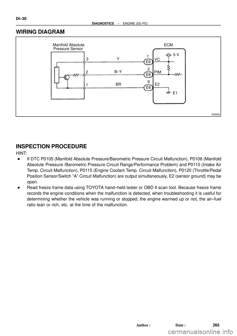
ECM Manifold Absolute
Pressure Sensor
1PIMVC
E2 Y
B±Y
BRE8
E8
E8 3
25 V
E1 1
2
9 DI±30
± DIAGNOSTICSENGINE (5S±FE)
265 Author�: Date�:
WIRING DIAGRAM
INSPECTION PROCEDURE
HINT:
�If DTC P0105 (Manifold Absolute Pressure/Barometric Pressure Circuit Malfunction), P0106 (Manifold
Absolute Pressure /Barometric Pressure Circuit Range/Performance Problem) and P0110 (Intake Air
Temp. Circuit Malfunction), P0115 (Engine Coolant Temp. Circuit Malfunction), P0120 (Throttle/Pedal
Position Sensor/Switch ºAº Circuit Malfunction) are output simultaneously, E2 (sensor ground) may be
open.
�Read freeze frame data using TOYOTA hand±held tester or OBD II scan tool. Because freeze frame
records the engine conditions when the malfunction is detected, when troubleshooting it is useful for
determining whether the vehicle was running or stopped, the engine warmed up or not, the air±fuel
ratio lean or rich, etc. at the time of the malfunction.
Page 2451 of 4770
BE6653P23721A03008A03407
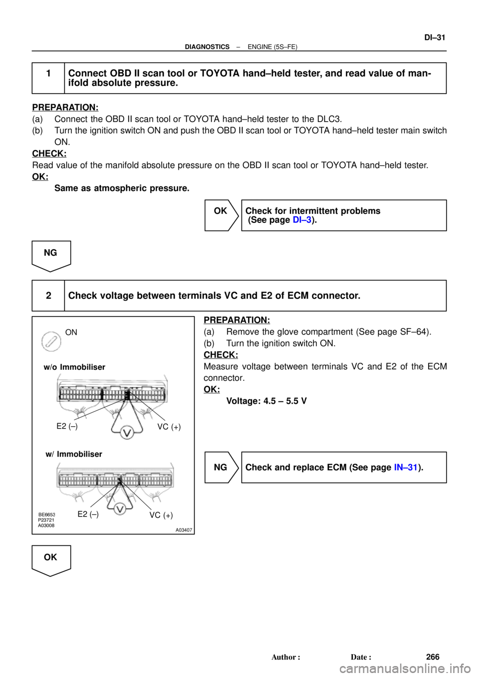
w/o Immobiliser
w/ ImmobiliserE2 (±)
VC (+)
ON
E2 (±)
VC (+)
± DIAGNOSTICSENGINE (5S±FE)
DI±31
266 Author�: Date�:
1 Connect OBD II scan tool or TOYOTA hand±held tester, and read value of man-
ifold absolute pressure.
PREPARATION:
(a) Connect the OBD II scan tool or TOYOTA hand±held tester to the DLC3.
(b) Turn the ignition switch ON and push the OBD II scan tool or TOYOTA hand±held tester main switch
ON.
CHECK:
Read value of the manifold absolute pressure on the OBD II scan tool or TOYOTA hand±held tester.
OK:
Same as atmospheric pressure.
OK Check for intermittent problems
(See page DI±3).
NG
2 Check voltage between terminals VC and E2 of ECM connector.
PREPARATION:
(a) Remove the glove compartment (See page SF±64).
(b) Turn the ignition switch ON.
CHECK:
Measure voltage between terminals VC and E2 of the ECM
connector.
OK:
Voltage: 4.5 ± 5.5 V
NG Check and replace ECM (See page IN±31).
OK
Page 2452 of 4770
BE6653P23722A03009A03408
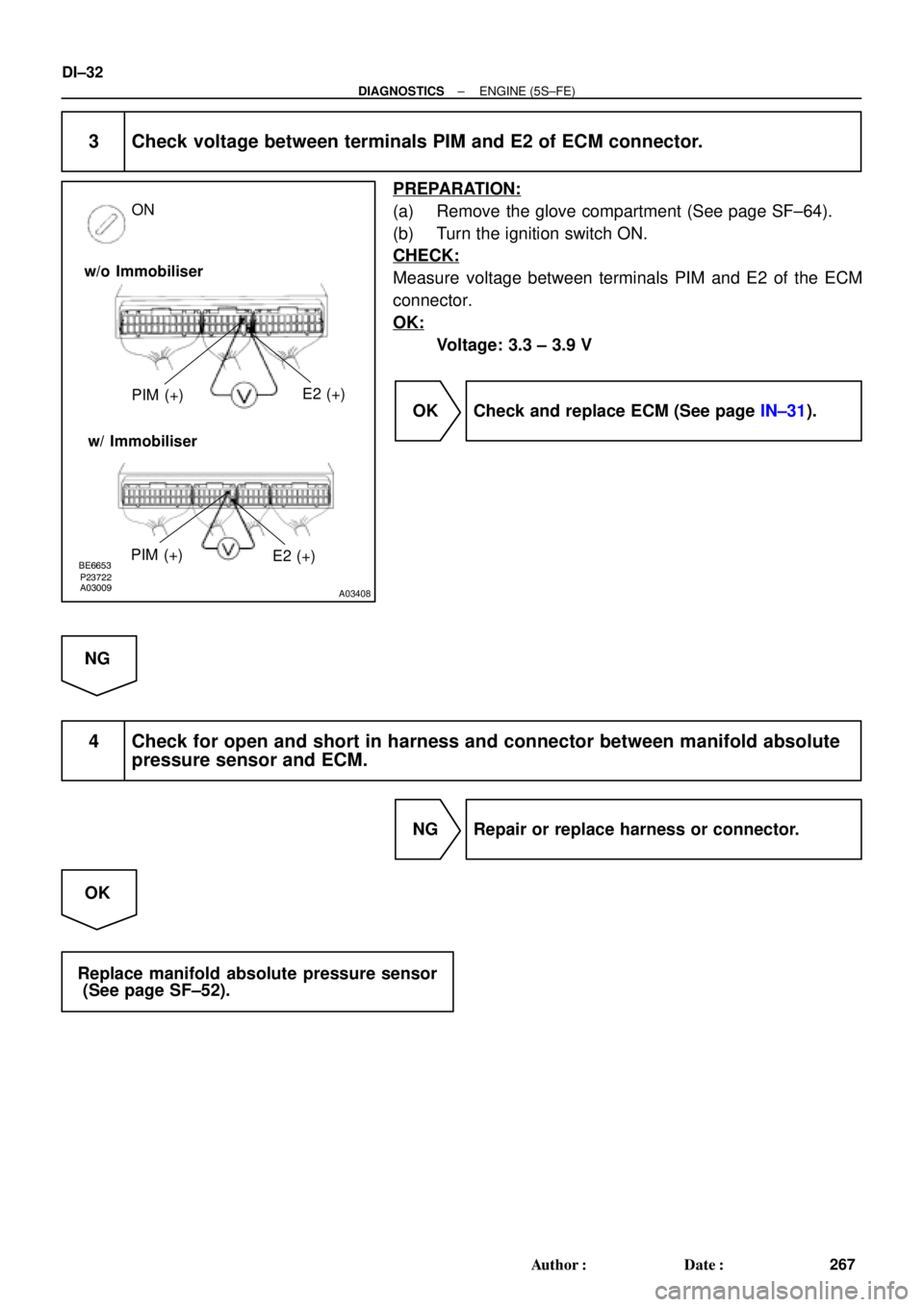
w/o Immobiliser
w/ ImmobiliserPIM (+)E2 (+)
ON
PIM (+)
E2 (+)
DI±32
± DIAGNOSTICSENGINE (5S±FE)
267 Author�: Date�:
3 Check voltage between terminals PIM and E2 of ECM connector.
PREPARATION:
(a) Remove the glove compartment (See page SF±64).
(b) Turn the ignition switch ON.
CHECK:
Measure voltage between terminals PIM and E2 of the ECM
connector.
OK:
Voltage: 3.3 ± 3.9 V
OK Check and replace ECM (See page IN±31).
NG
4 Check for open and short in harness and connector between manifold absolute
pressure sensor and ECM.
NG Repair or replace harness or connector.
OK
Replace manifold absolute pressure sensor
(See page SF±52).
Page 2453 of 4770

DI±33
268 Author�: Date�:
DTC P0106 Manifold Absolute Pressure Circuit
Range/Performance Problem
CIRCUIT DESCRIPTION
Refer to DTC P0105 (Manifold Absolute Pressure/Barom")
± DIAGNOSTICSENGINE (5S±FE)
DI±33
268 Author�: Date�:
DTC P0106 Manifold Absolute Pressure Circuit
Range/Performance Problem
CIRCUIT DESCRIPTION
Refer to DTC P0105 (Manifold Absolute Pressure/Barometric Pressure Circuit Malfunction) on page
DI±29.
DTC No.DTC Detecting ConditionTrouble Area
P0106
After engine is warmed up, conditions (a) and (b) continue with
engine speed 400 ~ 1,000 rpm
(2 trip detection logic)
(a) Throttle valve fully closed
(b) Manifold absolute pressure sensor output > 3.0 V
�Manifold absolute pressure sensorP0106Condition (c) and (d) continue with engine speed 2,500 rpm or
less
(2 trip detection logic)
(c) VTA > 1.85
(d) Manifold absolute pressure sensor output < 1.0 V
�Manifold absolute ressure sensor
�Vacuum line
WIRING DIAGRAM
Refer to DTC P0105 (Manifold Absolute Pressure/Barometric Pressure Circuit Malfunction) on page
DI±29.
INSPECTION PROCEDURE
HINT:
�If DTC P0105 (Manifold Absolute Pressure/Barometric Pressure Circuit Malfunction) and P0106 (Man-
ifold Absolute Pressure /Barometric Pressure Circuit Range/Performance Problem) are output simul-
taneously, manifold absolute pressure sensor circuit may be open. Perform troubleshooting of DTC
P0105 first.
�If DTC P0105 (Manifold Absolute Pressure/Barometric Pressure Circuit Malfunction), P0106 (Manifold
Absolute Pressure /Barometric Pressure Circuit Range/Performance Problem), P0110 (Intake Air
Temp. Circuit Malfunction), P0115 (Engine Coolant Temp. Circuit Malfunction) and P0120 (Throttle/
Pedal Position Sensor/Switch ºAº Circuit Malfunction) are output simultaneously, E2 (sensor ground)
may be open.
�Read freeze frame data using TOYOTA hand±held tester or OBD II scan tool. Because freeze frame
records the engine conditions when the malfunction is detected, when troubleshooting it is useful for
determining whether the vehicle was running or stopped, the engine warmed up or not, the air±fuel
ratio lean or rich, etc. at the time of the malfunction.
1 Are there any other codes (besides DTC P0106) being output?
YES Go to relevant DTC chart.
NO
DI00N±04
Page 2456 of 4770
A00310
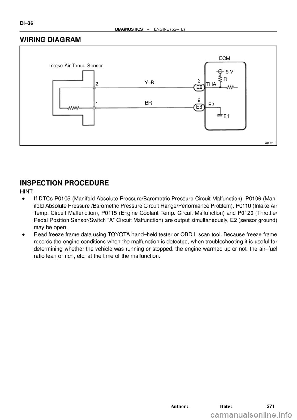
Intake Air Temp. Sensor
E8
E83
9ECM
5 V
THA
E2
E1 R
Y±B
BR 2
1 DI±36
± DIAGNOSTICSENGINE (5S±FE)
271 Author�: Date�:
WIRING DIAGRAM
INSPECTION PROCEDURE
HINT:
�If DTCs P0105 (Manifold Absolute Pressure/Barometric Pressure Circuit Malfunction), P0106 (Man-
ifold Absolute Pressure /Barometric Pressure Circuit Range/Performance Problem), P0110 (Intake Air
Temp. Circuit Malfunction), P0115 (Engine Coolant Temp. Circuit Malfunction) and P0120 (Throttle/
Pedal Position Sensor/Switch ºAº Circuit Malfunction) are output simultaneously, E2 (sensor ground)
may be open.
�Read freeze frame data using TOYOTA hand±held tester or OBD II scan tool. Because freeze frame
records the engine conditions when the malfunction is detected, when troubleshooting it is useful for
determining whether the vehicle was running or stopped, the engine warmed up or not, the air±fuel
ratio lean or rich, etc. at the time of the malfunction.
Page 2458 of 4770
A03010A03409
Intake Air Temp.
SensorECM
3
9
E8E8THA
E25 V
ON
E1
THAE2
w/o Immobiliser
w/ Immobiliser
THA
E2
DI±38
± DIAGNOSTICSENGINE (5S±FE)
273 Author�: Date�:
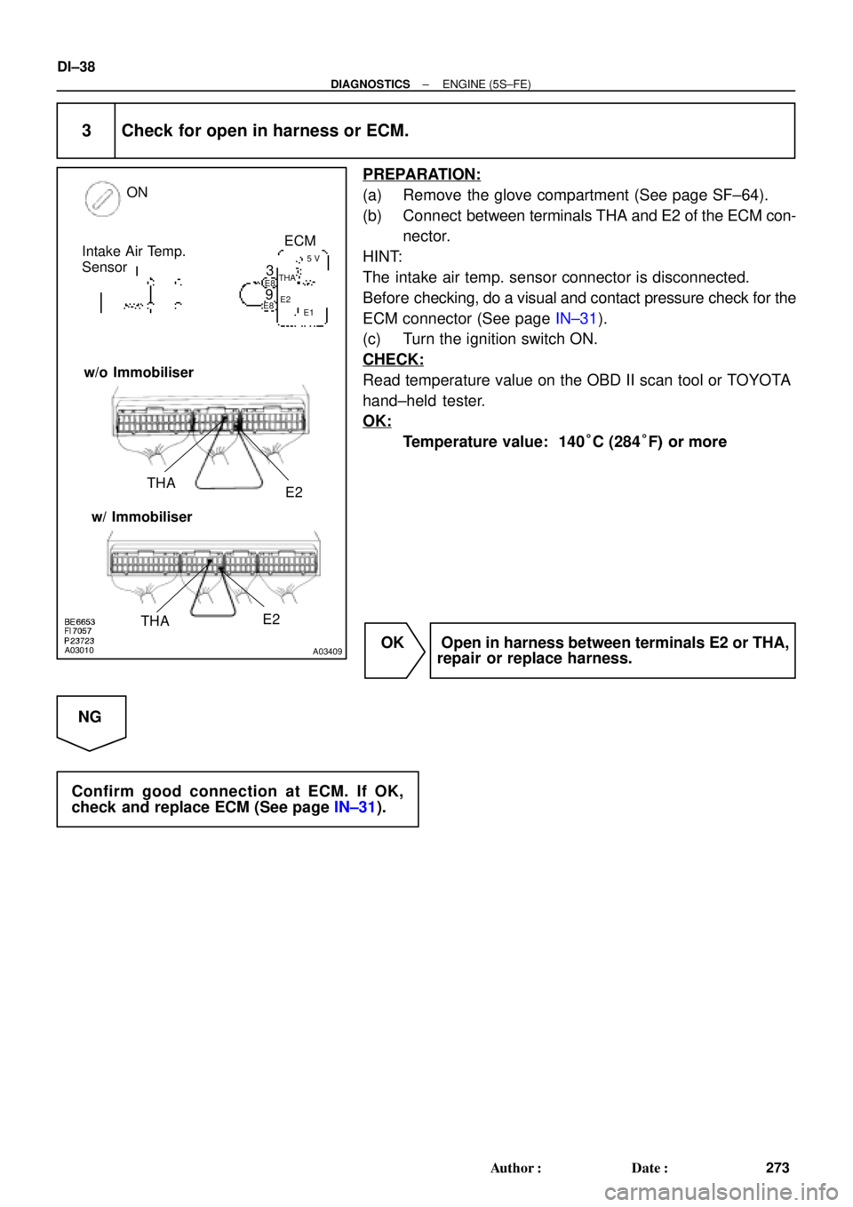
3 Check for open in harness or ECM.
PREPARATION:
(a) Remove the glove compartment (See page SF±64).
(b) Connect between terminals THA and E2 of the ECM con-
nector.
HINT:
The intake air temp. sensor connector is disconnected.
Before checking, do a visual and contact pressure check for the
ECM connector (See page IN±31).
(c) Turn the ignition switch ON.
CHECK:
Read temperature value on the OBD II scan tool or TOYOTA
hand±held tester.
OK:
Temperature value: 140°C (284°F) or more
OK Open in harness between terminals E2 or THA,
repair or replace harness.
NG
Confirm good connection at ECM. If OK,
check and replace ECM (See page IN±31).
Page 2462 of 4770
A00310
Engine Coolant Temp.
Sensor
2
1ECM
G±B
BR4
E8
E895 V
THW
E2
E1 R DI±42
± DIAGNOSTICSENGINE (5S±FE)
277 Author�: Date�:
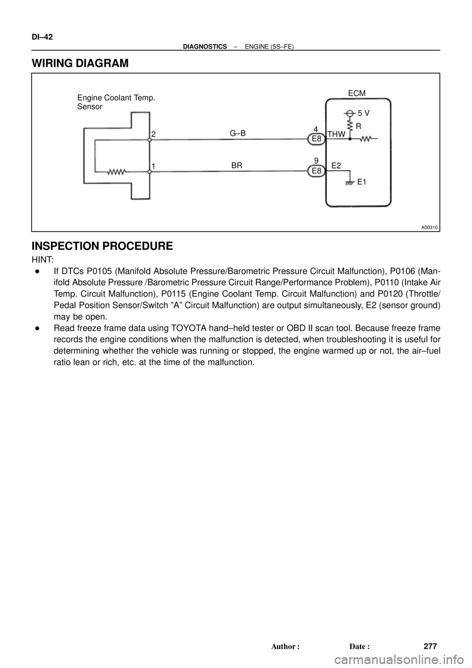
WIRING DIAGRAM
INSPECTION PROCEDURE
HINT:
�If DTCs P0105 (Manifold Absolute Pressure/Barometric Pressure Circuit Malfunction), P0106 (Man-
ifold Absolute Pressure /Barometric Pressure Circuit Range/Performance Problem), P0110 (Intake Air
Temp. Circuit Malfunction), P0115 (Engine Coolant Temp. Circuit Malfunction) and P0120 (Throttle/
Pedal Position Sensor/Switch ºAº Circuit Malfunction) are output simultaneously, E2 (sensor ground)
may be open.
�Read freeze frame data using TOYOTA hand±held tester or OBD II scan tool. Because freeze frame
records the engine conditions when the malfunction is detected, when troubleshooting it is useful for
determining whether the vehicle was running or stopped, the engine warmed up or not, the air±fuel
ratio lean or rich, etc. at the time of the malfunction.