Page 2625 of 4770
P20186
± DIAGNOSTICSENGINE (1MZ±FE)
DI±205
440 Author�: Date�:
7 Check fuel pressure.
PREPARATION:
(a) Be sure that enough fuel is in the tank.
(b) Connect the TOYOTA hand±held tester to the DLC3.
(c) Turn the ignition switch ON and push the TOYOTA hand±
held tester main switch ON.
(d) Use ACTIVE TEST mode to operate the fuel pump.
(e) If you have no TOYOTA hand±held tester, connect the
positive (+) and negative (±) leads from the battery to the
fuel pump connector (See page SF±6).
CHECK:
Check that the pulsation damper screw rises up when the fuel
pump operates.
NG Proceed to page SF±6 and continue to
troubleshoot.
OK
Page 2629 of 4770

DI±209
444 Author�: Date�:
(b) TOYOTA Enhanced Signals.
TOYOTA hand±held tester displayMeasurement ItemNormal Condition*
MISFIRE RPMEngine RPM for first misfire rangeM")
± DIAGNOSTICSENGINE (1MZ±FE)
DI±209
444 Author�: Date�:
(b) TOYOTA Enhanced Signals.
TOYOTA hand±held tester displayMeasurement ItemNormal Condition*
MISFIRE RPMEngine RPM for first misfire rangeMisfire 0: 0 rpm
MISFIRE LOADEngine load for first misfire rangeMisfire 0: 0 g/r
INJECTORFuel injection time for cylinder No.1Idling: 1.6 ~ 2.9 ms
IAC DUTY RATIOIntake Air Control Valve Duty Ratio
Opening ratio rotary solenoid type IAC valveIdling: 27 ~ 47 %
STARTER SIGStarter SignalCranking: ON
CTP SIGClosed Throttle Position SignalThrottle Fully Closed: ON
A/C SIGA/C Switch SignalA/C ON: ON
PNP SWPark/Neutral Position Switch SignalP or N position: ON
ELCTRCL LOAD SIGElectrical Load SignalDefogger switch ON: ON
STOP LIGHT SWStop Light Switch SignalStop light switch ON: ON
PS OIL PRESS SWPower Steering Oil Pressure Switch SignalTurn steering wheel: ON
FC IDLFuel Cut Idle: Fuel cut when throttle valve fully
closed, during decelerationFuel cut operating: ON
FC TAUFuel Cut TAU: Fuel cut during very light loadFuel cut operating: ON
CYL#1 ~ CYL#6Abnormal revolution variation for each cylinder0%
IGNITIONTotal number of ignition for every 1,000 revolu-
tions0 ~ 3,000
EGRT GASEGR Gas Temperature Sensor Value
EGR not operating:
Temperature between intake air temp. and
engine coolant temp.
INTAKE CTRL VSVIntake Air Control Valve VSV SignalVSV operating: ON
EGR SYSTEMEGR system operating conditionIdling: OFF
A/C CUT SIGA/C Cut SignalA/C S/W OFF: ON
FUEL PUMPFuel Pump SignalIdling: ON
EVAP (PURGE) VSVEVAP VSV SignalVSV operating: Above 30%
VAPOR PRESS VSVVapor Pressure VSV SignalVSV operating: ON (TANK)
*: If no conditions are specifically stated for ºldlingº, it means the shift lever is at N or P position, the A/C switch
is OFF and all accessory switches are OFF.
Page 2637 of 4770
DI07C±06
A07469
Engine Coolant
Temp. Sensor
Heated Oxygen Sensor
(Bank 1 Sensor 2) VSV for EVAP VSV for ACIS
Crankshaft Position
Sensor
Camshaft Position
Sensor
Heated Oxygen Sensor *1
(Bank 1 Sensor 1)
A/F Sensor*2
(Bank 1 Sensor 1)Park/Neutral Position Switch
Knock Sensor 1 Knock Sensor 2
EGR Gas Temp. Sensor InjectorDLC1ECMVSV for EGR
IAC ValveMass Air Flow MeterIgniter
*1 : Except California Specification vehicles
*2 : Only for California Specification vehiclesVapor Pressure
Sensor
DLC3
Heated Oxygen Sensor *1
(Bank 2 Sensor 1)
A/F Sensor*2
(Bank 2 Sensor 1)
Canister
EGR Valve
Position Sensor
± DIAGNOSTICSENGINE (1MZ±FE)
DI±217
452 Author�: Date�:
PARTS LOCATION
Page 2640 of 4770

455 Author�: Date�:
Symbols (Terminals No.)Wiring ColorConditionSTD Voltage (V)
TC (E11 ± 6) ± E1 (E10 ± 17)L±W eBRIG switch ON9 ~ 14
W (E7 ± 6) ± E01 (E1")
DI±220
± DIAGNOSTICSENGINE (1MZ±FE)
455 Author�: Date�:
Symbols (Terminals No.)Wiring ColorConditionSTD Voltage (V)
TC (E11 ± 6) ± E1 (E10 ± 17)L±W eBRIG switch ON9 ~ 14
W (E7 ± 6) ± E01 (E11 ± 21)G±R eBRIG switch ONBelow 3.0
PS (E10 ± 9) ± E1 (E10 ± 17)B±L eBRIG switch ON9 ~ 14
ACT (E8 13) E1 (E10 17)LG BBRA/C switch OFFBelow 2.0ACT (E8 ± 13) ± E1 (E10 ± 17)LG±B eBRA/C switch ON at idling9 ~ 14
A/C (E8 25) E1 (E10 17)BYBRA/C switch ON at idlingBelow 2.0A/C (E8 ± 25) ± E1 (E10 ± 17)B±Y eBRA/C switch OFF9 ~ 14
CF (E11 29) E1 (E10 17)GWBRElectric cooling fan is operating on high speed9 ~ 14CF (E11 ± 29) ± E1 (E10 ± 17)G±W eBRElectric cooling fan is operating on low speed or OFF0 ~ 2
TACH (E8± 27) ± E1 (E10 ± 17)B±O eBRIdlingPulse generation
TPC (E7 ± 9) ± E01 (E11 ± 21)W±R eBRIG switch ON
Disconnect the vacuum hose from the vapor pressure sensor9 ~ 14
PTNK (E7 17)IG switch ON3.0 ~ 3.6PTNK (E7 ± 17)
± E1 (E10 ± 17)L±R eBRIG switch ON
Apply vacuum 2.0 kPa (15 mmHg, 0.6 in.Hg)1.3 ~ 2.1
SIL (E7 ± 11) ± E1 (E10 ± 17)W eBRDuring transmissionPulse generation
STP (E7 15) E1 (E10 17)GWBR
IG switch ON
Brake pedal depressed7.5 ~ 14
STP (E7 ± 15) ± E1 (E10 ± 17)G±W eBRIG switch ON
Brake pedal releasedBelow 1.5
EGLS (E11 ± 22)WGBR
IG switch ON
Apply vacuum (0 kPa, 0 mmHg, 0 in.Hg) to EGR valve0.4 ~ 1.6EGLS (E11 22)
± E1 (E10 ± 17)W±G eBRIG switch ON
Apply vacuum (17.3 kPa, 130 mmHg, 5.12 in.Hg) to EGR valve3.2 ~ 5.1
*1
AFR+ (E10 ± 11
± E1 (E10 ± 17)BR eBRIG switch ON3.3*
*1
AFR± (E10 ± 20)
± E1 (E10 ± 17)B±R eBRIG switch ON3.0*
*1
AFL+ (E10 ± 12)
± E1 (E10 ± 17)B±W eBRIG switch ON3.3*
*1
AFL± (E10 ± 21)
± E1 (E10 ± 17)L eBRIG switch ON3.0*
*1
HAFR (E10 ± 3)BRBRIG switch ONBelow 3.0 HAFR (E10 3)
± E04 (E10 ± 1)B±R eBRIdling (warm up the engine)Pulse generation
*1
HAFL (E10 ± 4)BWBRIG switch ONBelow 3.0 HAFL (E10 4)
± E05 (E10 ± 8)B±W eBRIdling (warm up the engine)Pulse generation
KSW (E8 11) E1 (E10 17)LBBRAt time of inserting the keyBelow 1.5KSW (E8 ± 11) ± E1 (E10 ± 17)L±B eBRIn condition without the key inserted4 ~ 5
RXCK (E9 ± 5) ± E1 (E10 ± 17)R±L eBRAt time of inserting the keyPulse generation
CODE (E9 ± 4) ± E1 (E10 ± 17)G±W eBRAt time of inserting the keyPulse generation
IGSW (E7 ± 2) ± E1 (E10 ± 17)B±R eBRIG switch ON9 ~ 14
TXCT (E9± 10) ± E1 (E10 ± 17)L±Y eBRAt time of inserting the keyPulse
IMLD (E9 ± 16) ± E1 (E10 ± 17)R±Y eBRIn condition without the key insertedPulse
MREL (E7 ± 8) ± E1 (E10 ± 17)B±R eBRIG switch ON9 ~ 14
*: The ECM terminal voltage is fixed regardless of the output voltage from the sensor.
*
1: Only for California specification vehicles
Page 2651 of 4770

DI±231
466 Author�: Date�:
3 Check for o")
A02019
Intake Air Temp. Sensor ON22
18E10
E10THA5 V
E2
E2 THA
ECM
A00212
ON
Intake Air
Temp. Sensor
ECM
5 V
E2
22
THA
E10 E1018
± DIAGNOSTICSENGINE (1MZ±FE)
DI±231
466 Author�: Date�:
3 Check for open in harness or ECM.
PREPARATION:
(a) Remove the glove compartment (See page SF±73).
(b) Connect between terminals THA and E2 of ECM connec-
tor.
HINT:
Mass air flow meter connector is disconnected.
Before checking, do a visual and contact pressure check for the
ECM connector (See page IN±31).
CHECK:
Read temp. value on the OBD II scan tool or TOYOTA
hand±held tester.
OK:
Temp. value: 1405C (2845F) or more
OK Open in harness between terminal E2 or THA,
repair or replace harness.
NG
Confirm good connection at ECM.
If OK, check and replace ECM.
4 Check for short in harness and ECM.
PREPARATION:
(a) Disconnect the mass air flow meter connector.
(b) Turn the ignition switch ON.
CHECK:
Read temp. value on the OBD II scan tool or TOYOTA
hand±held tester.
OK:
Temp. value: ±405C (±405F)
OK Replace mass air flow meter.
NG
Page 2655 of 4770

DI±235
470 Author�: Date�:")
A02020
ON
Engine Coolant Temp. Sensor
ECM
THW E2
E10
E1014
185 V
THW
E2
1 2
A00216
ON
Engine Coolant
Temp. Sensor
ECM
5 V
E2 THWE1018 14
E10
± DIAGNOSTICSENGINE (1MZ±FE)
DI±235
470 Author�: Date�:
3 Check for open in harness or ECM.
PREPARATION:
(a) Remove the glove compartment (See page SF±73).
(b) Connect between terminals THW and E2 of the ECM con-
nector.
HINT:
Engine coolant temp. sensor connector is disconnected. Be-
fore checking, do a visual and contact pressure check for the
ECM connector (See page IN±31).
(c) Turn the ignition switch ON.
CHECK:
Read temperature. value on the OBD II scan tool or TOYOTA
hand±held tester.
OK:
Temperature value: 1405C (2845F) or more
OK Open in harness between terminal E2 or THW,
repair or replace harness.
NG
Confirm good connection at ECM.
If OK, check and replace ECM.
4 Check for short in harness and ECM.
PREPARATION:
(a) Disconnect the engine coolant temp. sensor connector.
(b) Turn the ignition switch ON.
CHECK:
Read temperature value on the OBD II scan tool or TOYOTA
hand±held tester.
OK:
Temperature value: ±405C (±405F)
OK Replace engine coolant temp. sensor.
NG
Page 2736 of 4770
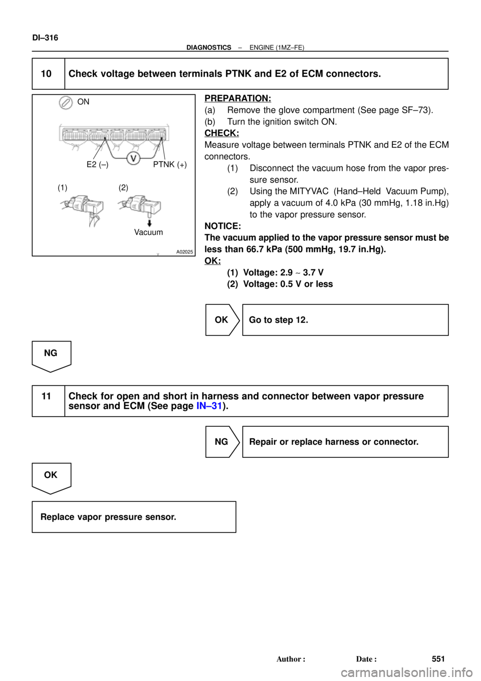
A02025
ON
E2 (±) PTNK (+)
Vacuum (1) (2)
DI±316
± DIAGNOSTICSENGINE (1MZ±FE)
551 Author�: Date�:
10 Check voltage between terminals PTNK and E2 of ECM connectors.
PREPARATION:
(a) Remove the glove compartment (See page SF±73).
(b) Turn the ignition switch ON.
CHECK:
Measure voltage between terminals PTNK and E2 of the ECM
connectors.
(1) Disconnect the vacuum hose from the vapor pres-
sure sensor.
(2) Using the MITYVAC (Hand±Held Vacuum Pump),
apply a vacuum of 4.0 kPa (30 mmHg, 1.18 in.Hg)
to the vapor pressure sensor.
NOTICE:
The vacuum applied to the vapor pressure sensor must be
less than 66.7 kPa (500 mmHg, 19.7 in.Hg).
OK:
(1) Voltage: 2.9 ~ 3.7 V
(2) Voltage: 0.5 V or less
OK Go to step 12.
NG
11 Check for open and short in harness and connector between vapor pressure
sensor and ECM (See page IN±31).
NG Repair or replace harness or connector.
OK
Replace vapor pressure sensor.
Page 2743 of 4770
BE6653
S00558 S00557A00474
ON
Air
E Air
E
F
F GG VSV is OFF VSV is ON
± DIAGNOSTICSENGINE (1MZ±FE)
DI±323
558 Author�: Date�:
10 Check VSV for vapor pressure sensor.
PREPARATION:
(a) Connect the TOYOTA hand±held tester to the DLC3.
(b) Turn the ignition switch ON and push the OBD II scan tool
or TOYOTA hand±held tester main switch ON.
(c) Select the ACTIVE TEST mode on the TOYOTA hand±
held tester.
CHECK:
Check the VSV operation when it is operated by TOYOTA
hand±held tester.
OK:
VSV is ON:
Air from pipe E is flowing out through pipe F.
VSV is OFF:
Air from pipe E is flowing out through pipe G.
OK Go to step 13.
NG
11 Check operation of VSV for vapor pressure sensor (See page SF±62).
OK Go to step 12.
NG
Replace VSV and charcoal canister, and then clean the vacuum hoses between charcoal canister
and VSV for vapor pressure sensor, and VSV for vapor pressure sensor and vapor pressure sen-
sor.

 VSV for EVAP VSV for ACIS
Crankshaft Position
Sensor
Camshaft Position
Sensor
Heated Oxygen Sensor *1
(Bank 1 Sensor")