Page 2464 of 4770
A03012A03411
ON
4 Engine Coolant
Temp. Sensor
2
1ECM
THWE2
5 V
THW
E1 E8
E8
9E2
w/o Immobiliser
w/ Immobiliser
THW
E2
DI±44
± DIAGNOSTICSENGINE (5S±FE)
279 Author�: Date�:
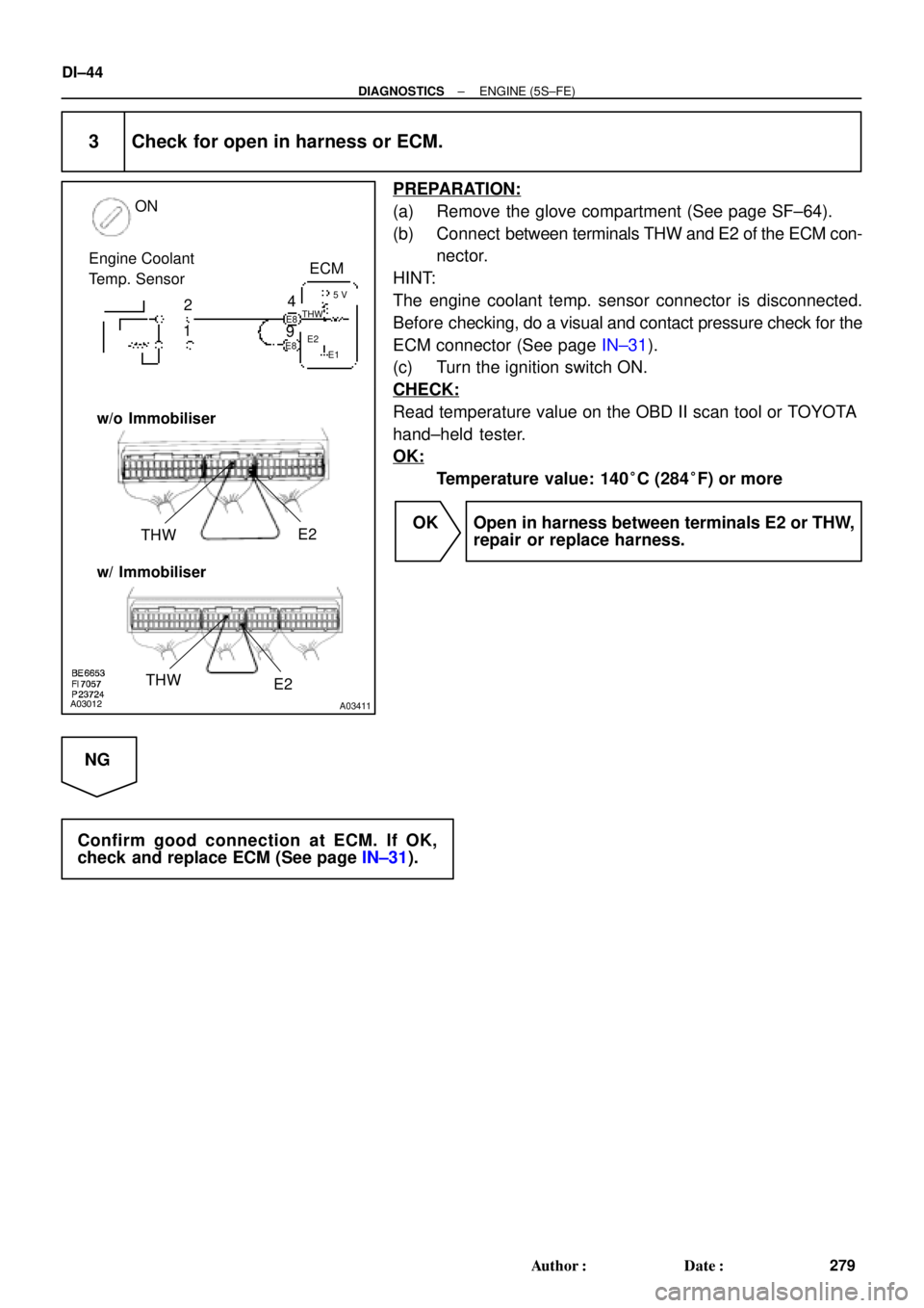
3 Check for open in harness or ECM.
PREPARATION:
(a) Remove the glove compartment (See page SF±64).
(b) Connect between terminals THW and E2 of the ECM con-
nector.
HINT:
The engine coolant temp. sensor connector is disconnected.
Before checking, do a visual and contact pressure check for the
ECM connector (See page IN±31).
(c) Turn the ignition switch ON.
CHECK:
Read temperature value on the OBD II scan tool or TOYOTA
hand±held tester.
OK:
Temperature value: 140°C (284°F) or more
OK Open in harness between terminals E2 or THW,
repair or replace harness.
NG
Confirm good connection at ECM. If OK,
check and replace ECM (See page IN±31).
Page 2470 of 4770

E8 E810
(*1)
DI±50
± DIAGNOSTICSENGINE (5S±FE)
285 Author�: Date�:
WIRING DIAGRAM")
A03595
Throttle Position Sensor
ECM
E8
E8 1
3
2Y
LG
BR1
11
9VC
VTA
E25 V
*1: w/o Immobiliser
*2: w/ Immobiliser(*2)
E8 E810
(*1)
DI±50
± DIAGNOSTICSENGINE (5S±FE)
285 Author�: Date�:
WIRING DIAGRAM
INSPECTION PROCEDURE
HINT:
�If DTCs P0105 (Manifold Absolute Pressure/Barometric Pressure Circuit Malfunction), P0106 (Man-
ifold Absolute Pressure /Barometric Pressure Circuit Range/Performance Problem), P0110 (Intake Air
Temp. Circuit Malfunction), P0115 (Engine Coolant Temp. Circuit Malfunction) and P0120 (Throttle/
Pedal Position Sensor/Switch ºAº Circuit Malfunction) are output simultaneously, E2 (sensor ground)
may be open.
�Read freeze frame data using TOYOTA hand±held tester or OBD II scan tool. Because freeze frame
records the engine conditions when the malfunction is detected, when troubleshooting it is useful for
determining whether the vehicle was running or stopped, the engine warmed up or not, the air±fuel
ratio lean or rich, etc. at the time of the malfunction.
Page 2527 of 4770

Idling
IG SW OFF
(1)(2)
Warm up
3 ~ 5 min.2 min.
3 ~ 5 min.Time (3)
(4)
(5)(6)
(7)
2 min.
± DIAGNOSTICSENGINE (5S±FE)
DI±107
342 Author�: Date�:
SYST")
P20769
Vehicle Speed
60 ~ 80 km/h
(38 ~ 50 mph)
Idling
IG SW OFF
(1)(2)
Warm up
3 ~ 5 min.2 min.
3 ~ 5 min.Time (3)
(4)
(5)(6)
(7)
2 min.
± DIAGNOSTICSENGINE (5S±FE)
DI±107
342 Author�: Date�:
SYSTEM CHECK DRIVING PATTERN
(1) Connect the OBD II scan tool or TOYOTA hand±held tester to the DLC3.
(2) Start and warm up the engine with all accessories switched OFF.
(3) Run the vehicle at 60 ~ 80 km/h (38 ~ 50 mph) for 3 min. or more.
(4) Idle the engine for about 2 min.
(5) Do steps (3) and (4) again.
(6) Stop at safe place and turn the ignition switch OFF.
(7) Do steps (2) to (5) again.
(8) Check the READINESS TESTS mode on the OBD II scan tool or TOYOTA hand±held tester.
If COMPL is displayed and the MIL does not light up, the system is normal.
If INCMPL is displayed and the MIL does not light up, run the vehicle again and check it.
HINT:
INCMPL is displayed when either condition (a) or (b) exists.
(a) The system check is incomplete.
(b) There is a malfunction in the system.
If there is a malfunction in the system, the MIL will light up after steps (2) to (5) above are done.
(2 trip detection logic)
INSPECTION PROCEDURE
HINT:
�If DTC P0105 (Manifold Absolute Pressure/Barometric Pressure Circuit Malfunction), P0106 (Manifold
Absolute Pressure/Barometric Pressure Circuit Range/Performance Problem) and P0401 (Exhaust
Gas Recirculation Flow Insufficient Detected) are output simultaneously, perform troubleshooting of
DTC P0105 first.
�If DTC P0401 (Exhaust Gas Recirculation Flow Insufficient Detected) and P0402 (Exhaust Gas Recir-
culation Flow Excessive Detected) are output simultaneously, perform troubleshooting of DTC P0402
first.
�Read freeze frame data using TOYOTA hand±held tester or OBD II scan tool. Because freeze frame
records the engine conditions when the malfunction is detected, when troubleshooting it is useful for
determining whether the vehicle was running or stopped, the engine warmed up or not, the air±fuel
ratio lean or rich, etc. at the time of the malfunction.
Page 2547 of 4770
A03018
A03420
PTNK (+)E2 (±)
(1)(2)
Vacuum ON
w/o Immobiliser
w/ Immobiliser
PTNK (+)
E2 (±)
± DIAGNOSTICSENGINE (5S±FE)
DI±127
362 Author�: Date�:
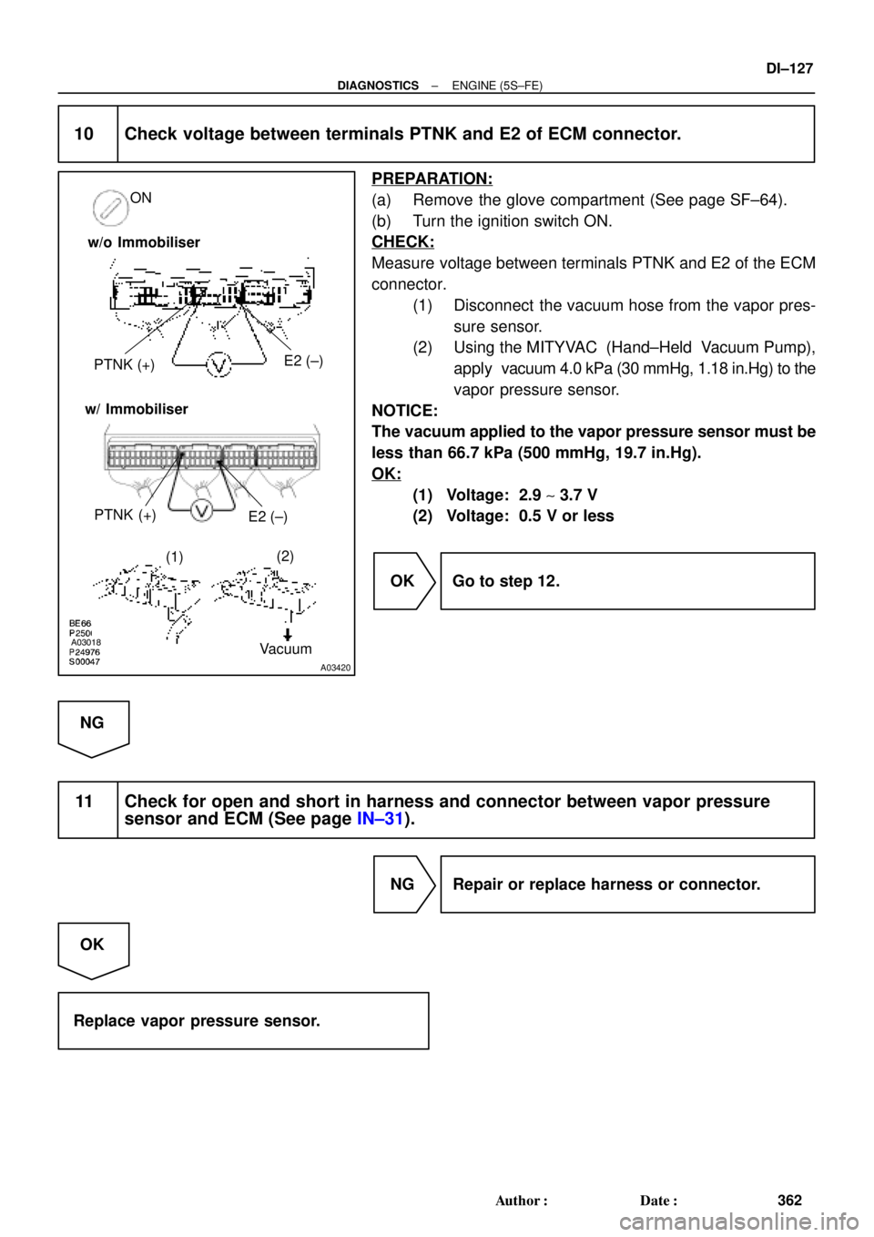
10 Check voltage between terminals PTNK and E2 of ECM connector.
PREPARATION:
(a) Remove the glove compartment (See page SF±64).
(b) Turn the ignition switch ON.
CHECK:
Measure voltage between terminals PTNK and E2 of the ECM
connector.
(1) Disconnect the vacuum hose from the vapor pres-
sure sensor.
(2) Using the MITYVAC (Hand±Held Vacuum Pump),
apply vacuum 4.0 kPa (30 mmHg, 1.18 in.Hg) to the
vapor pressure sensor.
NOTICE:
The vacuum applied to the vapor pressure sensor must be
less than 66.7 kPa (500 mmHg, 19.7 in.Hg).
OK:
(1) Voltage: 2.9 ~ 3.7 V
(2) Voltage: 0.5 V or less
OK Go to step 12.
NG
11 Check for open and short in harness and connector between vapor pressure
sensor and ECM (See page IN±31).
NG Repair or replace harness or connector.
OK
Replace vapor pressure sensor.
Page 2554 of 4770
A00472
ON
FE
G
FE
G
VSV is ON
VSV is OFF
DI±134
± DIAGNOSTICSENGINE (5S±FE)
369 Author�: Date�:
10 Check the VSV for vapor pressure sensor.
PREPARATION:
(a) Connect the TOYOTA hand±held tester to the DLC3.
(b) Turn the ignition switch ON and push the OBD II scan tool
or TOYOTA hand±held tester main switch ON.
(c) Select the ACTIVE TEST mode on the TOYOTA hand±
held tester.
CHECK:
Check the VSV operation when it is operated by TOYOTA
hand±held tester.
OK:
(1) VSV is ON:
Air from port E is flowing out through port F.
(2) VSV is OFF:
Air from port E is flowing out through port G.
OK Go to step 13.
NG
11 Check operation of VSV for vapor pressure sensor (See page SF±47).
OK Gp to step 12.
NG
Replace VSV charcoal canister, and then clean the vacuum hoses between charcoal canister and
VSV for vapor pressure sensor, and VSV for vapor pressure sensor and vapor pressure sensor.
Page 2556 of 4770
E2
(±) w/o Immobiliser
w/ Immobiliser
PTNK (+) E2(±)
DI±136
± DIAGNOSTICSENGINE (5S±")
A03018A03422
ON EngineStart
Stop
VSV for Vapor
Pressure
Sensor
OFFOFF
ON
VSV for
EVAP
5 sec. 5 sec.
PTNK
(+)E2
(±) w/o Immobiliser
w/ Immobiliser
PTNK (+) E2(±)
DI±136
± DIAGNOSTICSENGINE (5S±FE)
371 Author�: Date�:
14 Check vacuum hoses between charcoal canister and VSV for vapor pressure
sensor, and vapor pressure sensor and VSV for vapor pressure sensor.
CHECK:
(a) Check that the vacuum hose is connected correctly.
(b) Check the vacuum hose for looseness and disconnection.
(c) Check the vacuum hose for cracks, hole, damage and blockage.
NG Repair or replace.
OK
15 Check the charcoal canister.
PREPARATION:
(a) Remove the glove compartment (See page SF±64).
(b) Connect the TOYOTA hand±held tester to the DLC3.
(c) Remove the fuel tank cap.
(d) Disconnect the VSV connector for the vapor pressure
sensor.
(e) Select the ACTIVE TEST mode on the TOYOTA hand±
held tester.
(f) Start the engine.
(g) The VSV for the EVAP is ON by the TOYOTA hand±held
tester and remains on for 5 sec.
CHECK:
Measure voltage between terminals PTNK and E2 of the ECM
connector 5 sec. after switching the VSV for the EVAP from ON
to OFF.
OK:
Voltage: 2.5 V or less
NG Replace charcoal canister.
OK
Page 2560 of 4770
A03020A03424
ON
OFF
ONTPC
E
G
FFE
G
VSV is ON
VSV is OFF OFFONTPC
w/o Immobiliser
w/ Immobiliser
DI±140
± DIAGNOSTICSENGINE (5S±FE)
375 Author�: Date�:
8 Check for open and short in harness and connector between EFI main relay
(Marking: EFI) and VSV for EVAP, and VSV for EVAP and ECM (See page IN±31)
NG Repair or replace harness or connector.
OK
Check and replace ECM (See page IN±31).
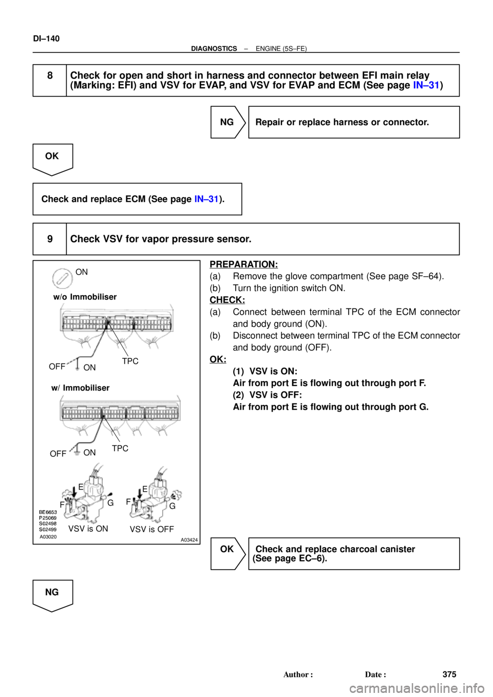
9 Check VSV for vapor pressure sensor.
PREPARATION:
(a) Remove the glove compartment (See page SF±64).
(b) Turn the ignition switch ON.
CHECK:
(a) Connect between terminal TPC of the ECM connector
and body ground (ON).
(b) Disconnect between terminal TPC of the ECM connector
and body ground (OFF).
OK:
(1) VSV is ON:
Air from port E is flowing out through port F.
(2) VSV is OFF:
Air from port E is flowing out through port G.
OK Check and replace charcoal canister
(See page EC±6).
NG
Page 2607 of 4770
A03030A03451
ON
FC
OFFON
Fuel Inlet Hose
FC
OFF
ON w/o Immobiliser
w/ Immobiliser
± DIAGNOSTICSENGINE (5S±FE)
DI±187
422 Author�: Date�:
6 Check for open in harness and connector between circuit opening relay (Mark-
ing: CIR OPN) and fuel pump, and fuel pump and body ground
(See page IN±31).
NG Repair or replace harness or connector.
OK
Check and replace ECM (See page IN±31).
OBD II scan tool (excluding TOYOTA hand±held tester):
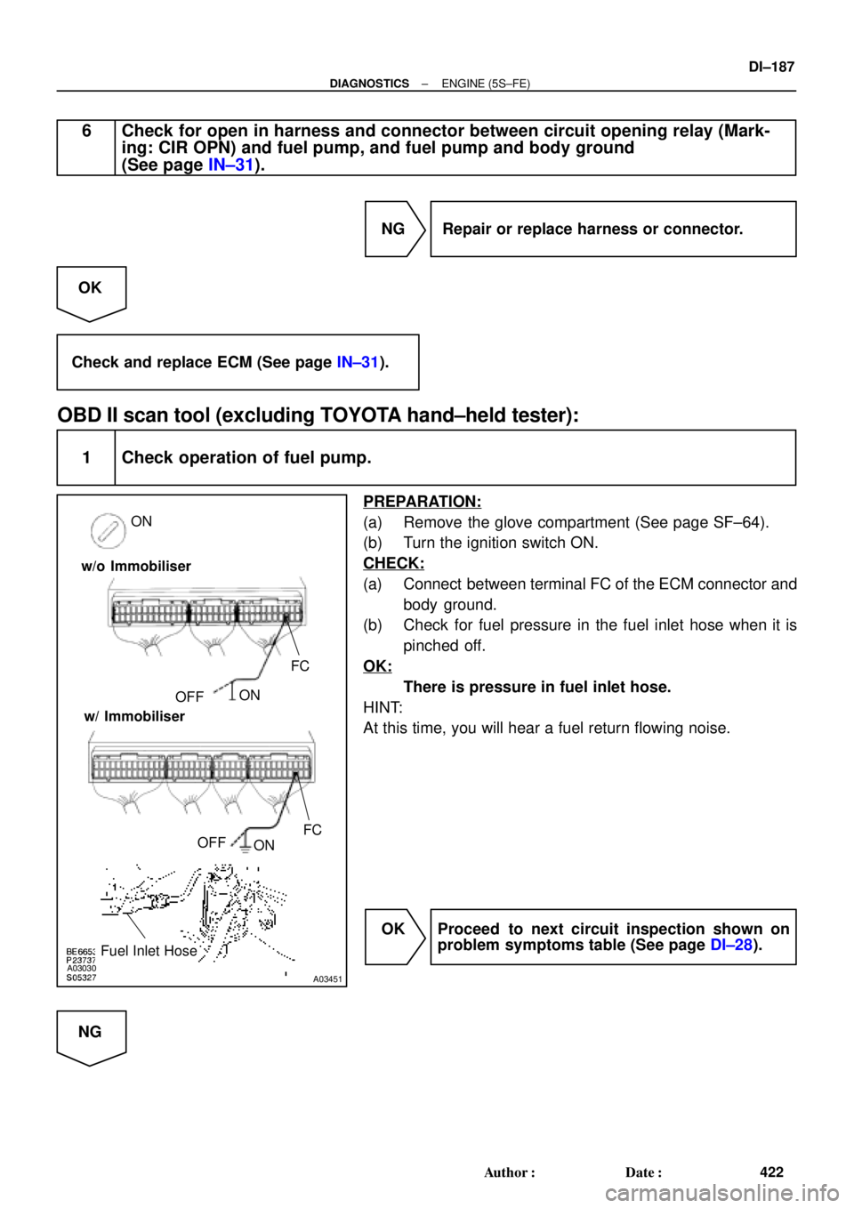
1 Check operation of fuel pump.
PREPARATION:
(a) Remove the glove compartment (See page SF±64).
(b) Turn the ignition switch ON.
CHECK:
(a) Connect between terminal FC of the ECM connector and
body ground.
(b) Check for fuel pressure in the fuel inlet hose when it is
pinched off.
OK:
There is pressure in fuel inlet hose.
HINT:
At this time, you will hear a fuel return flowing noise.
OK Proceed to next circuit inspection shown on
problem symptoms table (See page DI±28).
NG