Page 579 of 4770

104BODY ELECTRICALÐAIR CONDITIONING
3. Defroster Nozzle
The front defroster nozzle inner wall is modified into a radial configuration for a smoother air flow and improved
defroster performance.
4. Air Conditioning Amplifier
On the new Camry, the air conditioning amplifier that is provided on the 1MZ±FE engine model is an individual
amplifier unit type and on the 5S±FE engine model is a type that is integrated with the ECM.
The air conditioning amplifier controls the air conditioning system in accordance with the signals received from
sensors, switches, etc.
Function
Details
Magnetic Clutch Relay Control
�When the blower switch and the air conditioning switch are turned on to-
gether, or when the air outlet mode is switched to defroster, the magnetic
clutch relay turns on and activates the compressor.
�When one of the following conditions is met while the compressor is
turned on, the magnetic clutch relay is turned off and stops the compres-
sor:
i) The air temperature immediately after passing through the evaporator
is detected to be below 3�C (37.4�F) by the thermistor.
ii) The compressor speed detected by the lock sensor is compared with
the engine speed signal, and the compressor's slip rate exceeds a pre-
determined level (compressor locked).
iii) ªAir conditioner cutº was requested by the ECM to maintain engine
performance or idling speed.
Compressor Delay ControlWhen the air conditioning switch is turned on, the engagement of the mag-
netic clutch is delayed.
Air Conditioning Indicator Light
Control
�When the blower switch and the air conditioning switch are turned on to-
gether, or when the air outlet mode is switched to defroster, and the com-
pressor is activated, the indicator lamp of the air conditioning switch is
turned on.
�If compressure lock occurs during compressor operation, the indicator
lamp flashes every 1 second.
Page 721 of 4770
CAMRY ± NEW FEATURES
BATT
BATTERY
PS
IMLD
EGR
EVP1
TPC
W
ELS
STP
PTNK
TRC
TXCT
KSW
TC
SIL
EFI MAIN RELAY
+B
EFI ELS2 POWER STEERING OIL
PRESSURE SWITCH
TAILLIGHT & REAR WINDOW
DEFOGGER
STOP LIGHT SWITCH
VAPOR PRESSURE SENSOR
ABS & TRAC ECU*
1
TRANSPONDER KEY
AMPLIFIER*2
UNLOCK WARNING SWITCH*2
DATALINK CONNECTOR 1
DATALINK CONNECTOR 3EGR CONTROL
VSV
EVAP CONTROL
VSV
VAPOR PRESSURE CONTROL
VSV
THEFT DETERRENT INDICATOR
LIGHT*2
MALFUNCTION INDICATOR
LAMP
HTSOXYGEN SENSOR HEATER
CONTROL
HEATED OXYGEN SENSOR
HEATER (Bank 1, Sensor 2)
RXCK
CODE
12
*1: Applicable only to vehicles equipped with the TRAC System.
*
2: Applicable only to vehicles equipped with the Engine Immobiliser System.
Page 722 of 4770
CAMRY ± NEW FEATURES
150EG01
Circuit Opening RelayIgnition
SwitchEFI
Main
Relay
DLC1 Pressure
RegulatorVehicle Speed
SensorPark / Neutral Position Switch*
Fuel Pump
BatteryMIL
Air
Conditioning
Amplifier
DLC3
Stop Light Switch
Electrical Load Switch
Air-Fuel Ratio Sensor Heater Relay
ECM Fuel
Filter
Pulsation
DamperVSV
(for EVAP)Vapor
Pressure
Sensor
VSV
for Vapor
Pressure
Sensor
Charcoal CanisterVCV
Intake Air Temp.
SensorIAC Valve
VSV (for EGR)
Mass Air Flow
Meter
Air-Fuel Ratio Sensor
(Bank 1, Sensor 1)Throttle
Position
Sensor
Actuator
DIS
Injector
VSV (for ACIS)
EGR
Valve
Position
Sensor
EGR
Valve EGR Gas
Temp. Sensor Camshaft
Position
Sensor
Engine Coolant
Temp. SensorWU-TWC
WU-TWC
Crankshaft
Position SensorKnock Sensors
Air-Fuel Ratio Sensor
(Bank 2, Sensor 1)Heated Oxygen Sensor
(Bank 1, Sensor 2)
13
Engine Control System Diagram
1) California Specification Automatic Transaxle Model
*: Only for the Automatic Transaxle Models
Page 1076 of 4770
![TOYOTA CAMRY 2000 Service Repair Manual NF
NEW FEATURES Ð 5S-FNE ENGINE13
�FUEL SYSTEM
1. General
�The compressed gas [maximum pressure approximately 250 kg/cm2 (3600 psi, 24.8 MPa) @215C (705F)]
from the CNG fuel tank located in the rear](/manual-img/14/57447/w960_57447-1075.png "TOYOTA CAMRY 2000 Service Repair Manual NF
NEW FEATURES Ð 5S-FNE ENGINE13
�FUEL SYSTEM
1. General
�The compressed gas [maximum pressure approximately 250 kg/cm2 (3600 psi, 24.8 MPa) @215C (705F)]
from the CNG fuel tank located in the rear")
NF
NEW FEATURES Ð 5S-FNE ENGINE13
�FUEL SYSTEM
1. General
�The compressed gas [maximum pressure approximately 250 kg/cm2 (3600 psi, 24.8 MPa) @215C (705F)]
from the CNG fuel tank located in the rear section of the vehicle is routed via a fuel filter to the engine
compartment. The pressure of the fuel is then reduced to 8 kg/cm
2 (114 psi, 785 kPa).
�A pressure regulator and injectors designed exclusively for CNG application have been adopted.
�A fuel pressure sensor and a fuel temperature sensor that are used for the correction of the fuel injection
volume are located on the delivery pipe.
�The fuel tank, pressure regulator, and the delivery pipe are provided with shutoff valves that shut off
the fuel when the ignition switch is turned OFF.
In addition, these valves shut off the fuel when the engine stalls, the SRS airbag is deployed, or the
pressure in the main pipe becomes abnormally low.
�A fuel temperature sensor for the fuel gauge is mounted on the tank valve assembly, and a fuel pressure
sensor is mounted immediately upstream of the pressure regulator.
�Fuel System Diagram �
167CN12
Discharge
Valve
Fuel
Pressure
SensorFuel Temp.
SensorFuel
Pressure
RegulatorFuel Shutoff ValveFuel TankFuel Shutoff Valve
Relief Valve
Inlet Check
Valve
Fuel Temp.
Sensor
Coupler
Tank Valve Assembly
Vent Tube Manual
Shutoff
Valve Fuel
Filter
Fuel
Pressure
Sensor
Fuel Shutoff Valve Injectors
Delivery Pipe
Page 1078 of 4770

NF
NEW FEATURES Ð 5S-FNE ENGINE15
Fuel Shutoff Valve for Fuel Tank
This valve uses an solenoid valve. The main pipe that supplies compressed gas to the engine is connected
to this valve, which opens when the ignition switch is turned ON. If the engine stalls, this valve automatical-
ly shuts off the fuel even if the ignition switch is turned ON. The valve reopens upon restarting the engine.
Also, this valve shuts off the fuel if the SRS airbag is deployed in a collision or if the pressure in the
main pipe becomes abnormally low.
Inlet Check Valve
Connected to a filler pipe that guides the fuel that fills through the coupler, the inlet check valve shuts
off by the force of a spring and by the pressure of the gas in the tank.
During filling, the pressure of the filling gas opens the inlet check valve.
Relief Valve
A vent tube is connected to this valve.
If the fuel tank is exposed to an abnormally high temperature, this valve opens (by melting) to discharge
the CNG at a predetermined temperature, thus preventing the fuel tank from bursting due to the increase
in gas pressure.
The discharged CNG is guided under the floor through a vent tube and is released outside of the vehicle.
4. Coupler
The coupler allows the fuel to be filled when it is connected with a fuel filling nozzle. The coupler has
a built-in check valve to prevent the CNG from flowing backward.
5. Manual Shutoff Valve
This valve is mounted below the vehicle floor.
When servicing the vehicle, this valve can be manu-
ally turned 90 degrees to shut off the main pipe.
167CN09
Page 1082 of 4770

NF
NEW FEATURES Ð 5S-FNE ENGINE19
�ENGINE CONTROL SYSTEM
1. General
An engine control system based on the 5S-FE engine has been adopted. The knock sensor has been discontin-
ued because natural gas has a high octane value and is less susceptible to knocking.
The engine control system of 5S-FNE and 5S-FE engines are compared below.
System
Outline5S-FNE5S-FE
SFI
Sequential
A D-type SFI system is used, which indirectly detects
intake air volume by manifold absolute pressure sensor.��
Sequential
Multiport Fuel
Injection
The fuel injection system is a sequential multiport fuel
injection system.��
Ignition timing is determined by the ECM based on sig-
nals from various sensors.��
ESA
Electronic Spark
AdvanceThe ECM corrects the ignition timing in response to en-
gine knocking in accordance with the signals received
from the knock sensor.
�
Advance
Torque control correction during gear shifting had been
used to minimize the shift shock.��*1
IAC
(Idle Air Control)A rotary solenoid type IAC valve controls the fast idle
and idle speeds.�
(1-Coil Type
Built-in Driver)�(2-Coil Type)
Fuel Pump ControlFuel pump operation is controlled by signal from the
ECM.�
Fuel Cut-Off
Control
The fuel shutoff valves for the fuel tank, fuel pressure
regulator, and delivery pipe are shut off to stop the sup-
ply of fuel when the ignition switch is turned OFF or
during abnormal conditions (such as engine stalling,
SRS airbag deployed, etc.).
�Ð
Oxygen Sensor
and Air Fuel Ratio
Sensor
Heater ControlMaintains the temperature of the oxygen sensor and air
fuel ratio sensor at an appropriate level to increase accu-
racy of detection of the oxygen concentration in the ex-
haust gas.
��*2
EGR Cut-Off
ControlCuts off EGR according to the engine condition to
maintain drivability of the vehicle and durability of the
EGR components.
��
Evaporative
Emission ControlThe ECM controls the purge flow of evaporative emis-
sions (HC) in the charcoal canister in accordance with
engine conditions.
�
Air Conditioning
Cut-Off ControlBy turning the air conditioning compressor ON or OFF
in accordance with the engine condition, drivability is
maintained.
�*3�*3
When the ECM detects a malfunction, the ECM diag-
noses and memorized the failed section.��
DiagnosisThe diagnosis system includes a function that detects a
malfunction in the evaporative emission control sys-
tem.
�
Fail-Safe
When the ECM detects a malfunction, the ECM stops
or controls the engine according to the data already
stored in memory.
��
*1: Only for Automatic Transaxle Model
*
2: Air fuel ratio sensor only for California specification model.
*
3: The air conditioning magnet clutch controled by the ECM
Page 1083 of 4770

PIM
NE
G
THW
THA
VTA
AF
#10+
#20
#30
#40
IGT1,
IGT2
IGF
RSD
EGR
OX2
HTAF
HT2
MGC
FUEL W
PSW
ELS
NSW
F/PS
A/C SW
ECM
STA
SPD
R,2,L
STP
#40+ #30+ #20+ #10
FUEL")
NEW FEATURES Ð 5S-FNE ENGINE
(Continued)
PIM
NE
G
THW
THA
VTA
AF
#10+
#20
#30
#40
IGT1,
IGT2
IGF
RSD
EGR
OX2
HTAF
HT2
MGC
FUEL W
PSW
ELS
NSW
F/PS
A/C SW
ECM
STA
SPD
R,2,L
STP
#40+ #30+ #20+ #10
FUEL
20
2. Construction
The configuration of the engine control system in the 5S-FNE engine is as shown in the following chart.
SENSORS
MANIFOLD ABSOLUTE
PRESSURE SENSOR
CRANKSHAFT POSITION
SENSOR
CAMSHAFT POSITION
SENSOR
ENGINE COOLANT TEMP.
SENSOR
INTAKE AIR TEMP. SENSOR
THROTTLE POSITION SENSOR
IGNITION SWITCH
COMBINATION METER
wVehicle Speed Signal
AIR FUEL RATIO SENSOR
(Bank 1, Sensor 1)
HEATED OXYGEN SENSOR
(Bank 1, Sensor 2)
POWER STEERING OIL
PRESSER SWITCH
TAILLIGHT & REAR WINDOW
DEFOGGER SYSTEM
PARK/NEUTRAL POSITION
SWITCH
STOP LIGHT SWITCH
AIR CONDITIONING SWITCH
AIRBAG SENSOR ASSEMBLY
wFuel Cut-Off Signal
ACTUATORS
SFI
No. 1 INJECTOR
No. 2 INJECTOR
No. 3 INJECTOR
No. 4 INJECTOR
ESA
IGNITERS and
IGNITION COILS
SPARK PLUGS
IAC
CONTROL VALVE
EGR
VSV
AIR FUEL RATIO SENSOR
HEATER CONTROL
AIR FUEL RATIO SENSOR
HEATER
OXYGEN SENSOR HEATER
CONTROL
HEATED OXYGEN SENSOR
HEATER
AIRE CONDITIONING
CUT-OFF CONTROL
MAGNET CLUTCH RERAY
FUEL GAGE
LOW FUEL LEVEL WARNING
LIGHT
Page 1526 of 4770
I01386
AC±4
± AIR CONDITIONINGAIR CONDITIONING SYSTEM
2486 Author�: Date�:
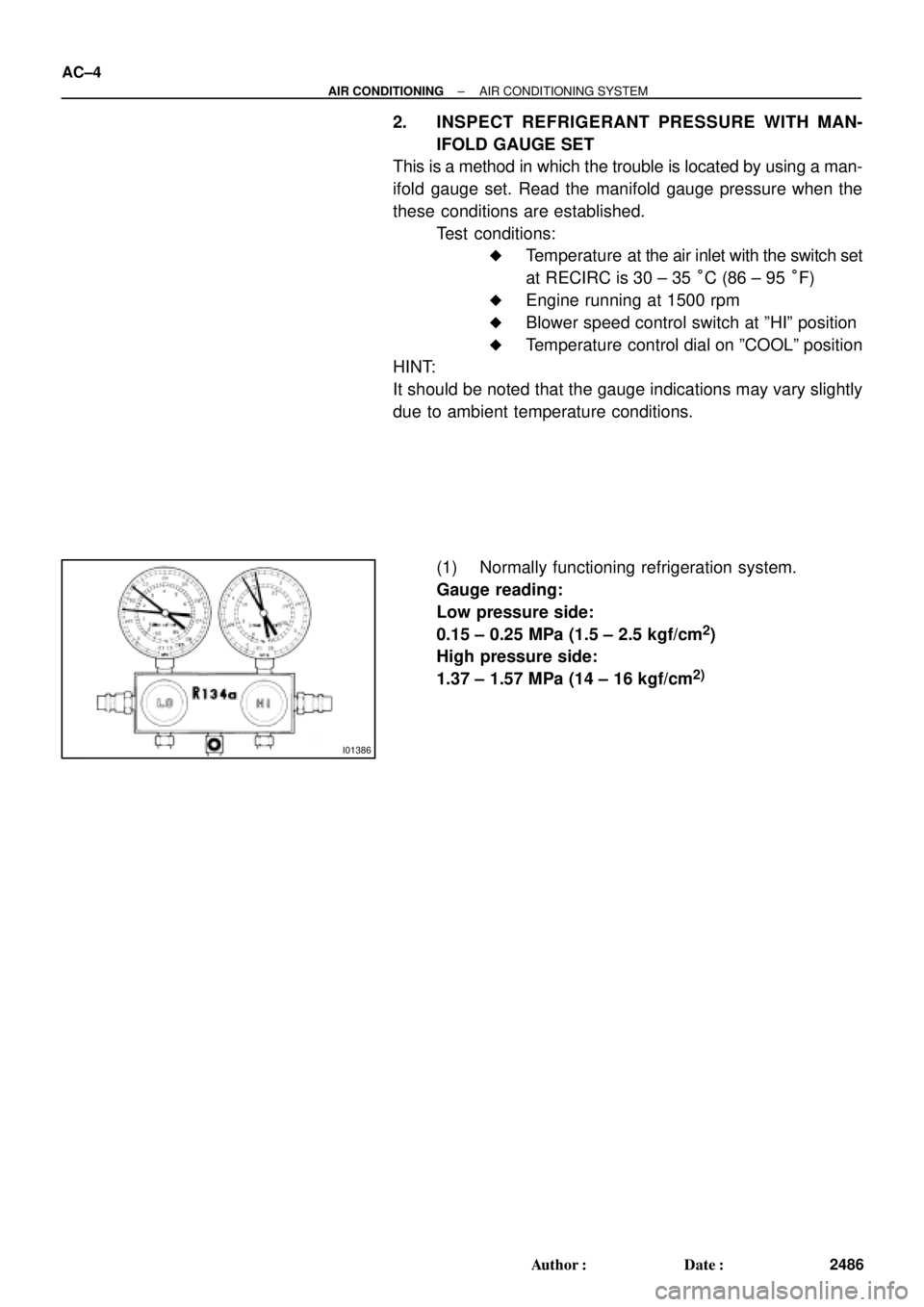
2. INSPECT REFRIGERANT PRESSURE WITH MAN-
IFOLD GAUGE SET
This is a method in which the trouble is located by using a man-
ifold gauge set. Read the manifold gauge pressure when the
these conditions are established.
Test conditions:
�Temperature at the air inlet with the switch set
at RECIRC is 30 ± 35 °C (86 ± 95 °F)
�Engine running at 1500 rpm
�Blower speed control switch at ºHIº position
�Temperature control dial on ºCOOLº position
HINT:
It should be noted that the gauge indications may vary slightly
due to ambient temperature conditions.
(1) Normally functioning refrigeration system.
Gauge reading:
Low pressure side:
0.15 ± 0.25 MPa (1.5 ± 2.5 kgf/cm
2)
High pressure side:
1.37 ± 1.57 MPa (14 ± 16 kgf/cm
2)