Page 99 of 4770
NOTICE:
wSupport the timing belt, :o the meshing of crank±
shaft timing pulley and timing belt does not shift.
wBe careful not to drop anything inside the timing
belt cover.
wDo not allow the belt to come into correct with oil,
water or dust.
30. REMOVE ENGINE HANGERS
Remove the bolt and engine hanger. Remove the 2
engine hangers. Remove the ground strap.
31. REMOVE GENERATOR BRACKET
Remove the 3 bolts and generator bracket.
32. REMOVE OIL PRESSURE SWITCH 27. REMOVE CAMSHAFT TIMING PULLEY
(See steps 2 to 15 on pages EG1±26 to 28)
28. REMOVE NO. 1 IDLER PULLEY AND TENSION
SPRING
Remove the bolt, pulley and tension spring.
33. REMOVE CYLINDER HEAD COVER
Remove the 4 nuts, grommets, head cover and gasket.29. REMOVE NO.3 TIMING BELT COVER
Remove the 4 bolts and timing and cover.
± 5S±FE ENGINEENGINE MECHANICALEG1±49
Page 123 of 4770
10. INSTALL GENERATOR BRACKET
Install the generator bracket with the 3 bolts.
Torque: 42 N±m (425 kgf±cm, 31 ft±lbf)
11. INSTALL ENGINE HANGERS
Install the engine hanger with the bolt. Install the 2
engine hangers. Install the ground strap.
Torque: 25 N±m (250 kgf±cm, 18 ft±lbf)
(c) Install the gasket to the head cover.
(d) Install the head cover with the 4 grommets and nuts.
Uniformly tighten the nuts in several passes.
Torque: 23 N±m (230 kgf±cm, 17 ft±lbf)
HINT: Install the grommets so that their markings are
as shown in the illustration.
9. INSTALL OIL PRESSURE SWITCH
Apply adhesive to 2 or 3 threads.
Adhesive:
Part No.08833±00080, THREE BOND 1324 or equivalent
12. INSTALL NO.3 TIMING BELT COVER
Install the timing belt cover with the 4 bolts.
Torque: 7.8 N±m (80 kgf±cm, 69 in±lbf)
± 5S±FE ENGINEENGINE MECHANICALEG1±73
Page 130 of 4770
31. ASSEMBLE EXHAUST MANIFOLD AND WARM UP
THREE±WAY CATALYTIC CONVERTER
Assemble the following parts:
(1) WU±TWC
(2) Cushion
(3) Retainer
(4) Gasket
(5) Exhaust manifold
(6) 3 bolts and 2 nuts
Torque: 29 N±m (300 kgf±cm, 22 ft±lbf)
(c) Connect the following connectors:
(1) Engine coolant temperature sender gauge con±
nector
(2) Engine coolant temperature sensor connector
29. CONNECT ENGINE WIRE (FOR OXYGEN SENSORS)
TO ENGINE HANGER
30. CONNECT OIL PRESSURE SWITCH CONNECTOR
32. INSTALL EXHAUST MANIFOLD AND WARM UP
THREE±WAY CATALYTIC CONVERTER
ASSEMBLY
(a) Install a new gasket, the exhaust manifold and WU ±
TWC assembly with the 6 nuts. Uniformly tighten the
nuts in several passes.
Torque: 49 N±m (540 kgf±cm, 36 ft±lbf)
(7) 2 converter heat insulators
(8) 8 bolts
(9) Manifold lower heat insulator
(10) 3 bolts
± 5S±FE ENGINEENGINE MECHANICALEG1±80
Page 226 of 4770
5. Check that there are no fuel leaks after performing
maintenance anywhere on the fuel system.
(a) Using SST, connect terminals + B and FP of the data
link connector 1.
SST 09843±18020
(b) With engine stopped, turn the ignition switch ON.
(c) Pinch the fuel return hose. The pressure in high pres±
sure line will rise to approx. 392 kPa (4kgf/cm2, 57
psi). In this state, check to see that there are no leaks
from any part of the fuel system.
NOTICE: Always pinch the hose. Avoid bending as it may
cause the hose to crack.
(d) Turn the ignition switch OFF.
(9) Remove the SST.
SST 09843±18020
± 5S±FE ENGINEMFI/SFI SYSTEMEG1±176
Page 228 of 4770
2. CHECK FUEL PRESSURE
(a) Check that the battery voltages is above 12 volts.
(b) Disconnect the negative (±) terminal cable from the
battery.
CAUTION: Work must be started after 90 seconds from
the time the ignition switch is turned to the ªLOCKº
position and the negative (±) terminal cable is discon±
nected from the battery.
If there is no pressure, check the following parts:
wFusible link
wFuses (AM2 30A, EFI 15A, IGN 7.5A)
wEFI main relay
wFuel pump
wWiring connections (c) Check that there is pressure in the hose from the fuel
filter.
HINT: At this time, you will hear fuel return noise.
(e) Remove the SST.
SST 09843±18020 (d) Turn the ignition switch OFF.
± 5S±FE ENGINEMFI/SFI SYSTEMEG1±178
Page 229 of 4770
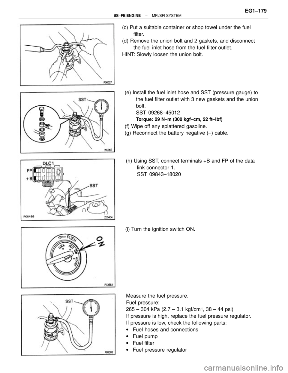
Measure the fuel pressure.
Fuel pressure:
265 ± 304 kPa (2.7 ± 3.1 kgf/cm�, 38 ± 44 psi)
If pressure is high, replace the fuel pressure regulator.
If pressure is low, check the following parts:
wFuel hoses and connections
wFuel pump
wFuel filter
wFuel pressure regulator (e) Install the fuel inlet hose and SST (pressure gauge) to
the fuel filter outlet with 3 new gaskets and the union
bolt.
SST 09268±45012
Torque: 29 N±m (300 kgf±cm, 22 ft±lbf)
(f) Wipe off any splattered gasoline.
(g) Reconnect the battery negative (±) cable. (c) Put a suitable container or shop towel under the fuel
filter.
(d) Remove the union bolt and 2 gaskets, and disconnect
the fuel inlet hose from the fuel filter outlet.
HINT: Slowly loosen the union bolt.
(h) Using SST, connect terminals +B and FP of the data
link connector 1.
SST 09843±18020
(i) Turn the ignition switch ON.
± 5S±FE ENGINEMFI/SFI SYSTEMEG1±179
Page 271 of 4770
MAP SENSOR INSPECTION
1. INSPECT POWER SOURCE VOLTAGE OF MAP
SENSOR
(a) Disconnect the MAP sensor connector.
(b) Turn the ignition switch ON.
(c) Using a voltmeter measure the voltage between con±
nector terminals VC and E2 of the wiring harness side.
Voltage:
4.75 ± 5.25 V
(d) Reconnect the MAP sensor connector.
MANIFOLD ABSOLUTE PRESSURE
(MAP) SENSOR
± 5S±FE ENGINEMFI/SFI SYSTEMEG1±221
Page 272 of 4770
2. INSPECT POWER OUTPUT OF MAP SENSOR
(a) Turn the ignition switch ON.
(b) Disconnect the vacuum hose on the air intake cham±
ber side.
(c) Connect a voltmeter to terminals PIM and E2 of the
ECM, and measure the output voltage under ambient
atmospheric pressure.
(d) Apply vacuum to the MAP sensor in 13.3 kPa (100
mmHg, 3.94 in.Hg) segments to 66.7 kPa (500 mmHg,
19.69 in.Hg).
(e) Measure the voltage drop from step
(c) above for each
segment.
Voltage drop:
Applied
Vacuum
kPa
(mmHg
in.Hg)66.7
( 500
19.69) 53.5
( 400
15.75) 40.0
( 300
111.8) 13.3
(100
3.94 )26.7
(200
7.87)
Voltage
drop V0.7±0.9
0.3±0.5
1.1 ±1.3 1.5 ± 1.71.9 ± 2.1
± 5S±FE ENGINEMFI/SFI SYSTEMEG1±222


11. INSTALL ENGINE HANGERS
Install the engine hanger with the bolt. Install the")
 WU±TWC
(2) Cushion
(3) Retainer
(4) Gasket
(5) Exhaust manifold
(6) 3 bolts and 2 nuts
Torqu")
 Using SST, connect terminals + B and FP of the data
link connector 1.
SST 09843±18020
(b) With engi")
 Check that the battery voltages is above 12 volts.
(b) Disconnect the negative (±) terminal cable from the
battery.
CAUTION: Work must be started after 90 seconds from
the")
 Disconnect the MAP sensor connector.
(b) Turn the ignition switch ON.
(c) Using a voltmeter measure the voltage between con±
ne")
 Turn the ignition switch ON.
(b) Disconnect the vacuum hose on the air intake cham±
ber side.
(c) Connect a voltmeter to terminals PIM and E2 of the
ECM, and")