Page 1898 of 4770
AUTOMATIC TRANSAXLECOMPONENT PARTS INSTALLATION ±
AX±102
DIFFERENTIAL AND DRIVE PINION
INSTALLATION
1. INSTALL DRIVE PINION INTO TRANSAXLE CASE
(a) Using SST, install the bearing to the drive pinion shaft.
SST 09350±32014 (09351±32120)
(b) Place the bearing cage onto the drive pinion shaft.
NOTICE: Be careful not to damage the oil seals with the
pinion shaft.
(c) Using a brass bar and hammer, slightly tap the bearing
cage into the transaxle case until the snap ring groove in
the bore can be seen.
(d) Using SST, install snap ring into the bore.
SST 09350±32014 (09351±32050)
(e) Using SST, install the snap ring.
SST 09350±32014 (09351±32050)
AX0U1±02
Page 1900 of 4770
AUTOMATIC TRANSAXLECOMPONENT PARTS INSTALLATION ±
AX±104
�If the preload is less then specified, retighten the nut
13 N´m (130 kgf´cm, 9 ft´lbf) at a time until the speci-
fied preload is reached.
If the maximum torque is exceeded while retightening the
nut, replace the bearing spacer and repeat the preload
procedure.
Do not back off the nut to reduce the preload.
Maximum torque: 353 N´m (3,600 kgf´cm, 260 ft´lbf)
(e) If the preload is adjusted within specification, make a note
of it.
(f) Stroke the lock nut.
6. INSTALL APPLY GASKET
7. PLACE OUTER RACE AND SHIM ONTO RH SIDE
BEARING
8. PLACE DIFFERENTIAL CASE INTO TRANSAXLE
CASE
Be sure to install the shim and outer race into place.
Page 1901 of 4770
 Remove any packing material and be careful not to drop
oil on the contacting surfaces of the carrier cover and
t")
AUTOMATIC TRANSAXLECOMPONENT PARTS INSTALLATION ±
AX±105
9. INSTALL CARRIER COVER
(a) Remove any packing material and be careful not to drop
oil on the contacting surfaces of the carrier cover and
transaxle case.
(b) Apply seal packing to the carrier cover.
Seal packing:
Part No.08826±00090, THREE BOND 1281 or equiva-
lent
HINT: Install the carrier cover within 10 minutes after ap-
plying seal packing.
(c) Install and torque the 11 bolts.
Torque: 39 N´m (400 kgf´cm, 29 ft´lbf)
HINT: Each bolt length is indicated below.
Bolt length:
Bolt A: 100 mm (3.937 in.)
Bolt B: 65 mm (2.559 in.)
Bolt C: 75 mm (2.953 in.)
10. ADJUST SIDE BEARING PRELOAD
(a) Remove any packing material on the contacting surfaces
of the LH bearing retainer and transaxle case.
HINT: Do not apply seal packing yet.
(b) Install the LH bearing retainer and torque the 6 bolts.
Torque: 19 N´m (195 kgf´cm, 14 ft´lbf)
(c) Snap down the bearings by turning the differential case
several times.
(d) Using a small torque wrench, measure the differential to-
tal preload.
Total preload (at starting):
New bearing
Drive pinion preload plus 0.2±0.4 N´m
(2.5±5.1 kgf´cm, 2.2±3.6 in.´lbf)
Reused bearing
Drive pinion preload plus 0.1±0.2 N´m
(1.3±2.0 kgf´cm, 1.1±1.7 in.´lbf)
If the preload is not within specification, replace the ad-
justing shim in the LH bearing retainer with one of a differ-
ent thickness.
Page 1902 of 4770

MarkThicknessMarkThickness
02.00 (0.0787)92.45 (0.0965)
12.05 (0.0807)A2.50 (0.0984)
22.10 (0.0827)")
AUTOMATIC TRANSAXLECOMPONENT PARTS INSTALLATION ±
AX±106
AT3700:Adjusting shim thickness
mm (in.)
MarkThicknessMarkThickness
02.00 (0.0787)92.45 (0.0965)
12.05 (0.0807)A2.50 (0.0984)
22.10 (0.0827)B2.55 (0.1004)
32.15 (0.0846)C2.60 (0.1024)
42.20 (0.0866)D2.65 (0.1043)
52.25 (0.0886)E2.70 (0.1063)
62.30 (0.0906)F2.75 (0.1083)
72.35 (0.0925)G2.80 (0.1102)
82.40 (0.0945)H2.85 (0.1122)
11. INSTALL LH BEARING RETAINER
(a) Remove the 6 bolts and LH bearing retainer.
(b) Remove any FIPG material on the contacting surfaces of
LH bearing retainer, transaxle case and carrier cover.
(c) Apply FIPG to the transaxle case and carrier cover.
FIPG: Part No.08826±00090, THREE BOND 1281 or equiva-
lent
HINT: Install the LH bearing retainer within 10 minutes af-
ter applying FIPG.
(d) Install the LH bearing retainer.
(e) Coat the threads of bolts with sealer.
Sealer: Part No.08833±00070, THREE BOND 1324 or equiv-
alent
(f) Tighten the bolts.
Torque: 19 N´m (195 kgf´cm, 14 ft´lbf)
(g) Snap down the bearings.
(h) Recheck the differential total preload.
Page 1926 of 4770
AUTOMATIC TRANSAXLESERVICE SPECIFICATIONS ±
AX±130
Accumulator Spring
SpringFree length mm (in.)Color
C0Inner
Outer47.5 (1.870)
16.3 (0.642)White
None
C173.6 (2.898)None
C251.8 (2.039)Yellow / Purple
B066.8 (2.630)Red / Yellow
B2Inner
Outer70.3 (2.767)
88.2 (3.473)None
None
Differential Assembly
Drive pinion preload (at Starting)
New bearing1.0 ± 1.6 N´m
10 ± 16 kgf´cm 8.7 ± 13.9 in.´lbf
Reused bearing0.5 ± 0.8 N´m
5 ± 8 kgf´cm 4.3 ± 6.9 in.´lbf
Total preload (at starting)
New bearingDrive pinion preload plus 0.3 ± 0.4 N´m
2.8 ± 4.4 kgf´cm 2.4 ± 3.8 in.´lbf
Reused bearingDrive pinion preload plus 0.1 ± 0.2 N´m
1.4 ± 2.2 kgf´cm 1.2 ± 1.9 in.´lbf
Pinion to side gear backlash0.05 ± 0.20 mm
0.0020 ± 0.0079 in.
Side gear thrust washer thickness
1.60 mm
0.0630 in.
1.70 mm
0.0670 in.
1.80 mm
0.0709 in.
Page 1928 of 4770
AUTOMATIC TRANSAXLESERVICE SPECIFICATIONS ±
AX±132
TORQUE SPECIFICATIONS
Part tightenedN´mkgf´cmft´lbf
Oil cooler pipe union2727520
Oil pan4.95043 in.´lbf
Valve body x Transaxle case1111 08
Accumulator x Cover101007
Oil pump x Transaxle case2222516
O/D case x Transaxle case2525018
Differential LH side bearing retainer1919514
Differential RH retainer1919514
Differential carrier cover3940029
Oil pump body x Stator shaft101007
Ring gear x Differential case1241,26091
Upper valve body x Lower valve body6.66758 in.´lbf
Accumulator cylinder x Valve body6.66758 in.´lbf
Solenoid x Valve body6.66758 in.´lbf
Counter drive gear lock nut2802,855206
Carrire cover x Transaxle case3940029
Parking lock pawl bracket7.47565 in.´lbf
Oil strainer x Transaxle case1111 08
AX04N±03
Page 1943 of 4770
Q00394
SST
AX03S±01
Q06348
SST
Q00238
SST
± AUTOMATIC TRANSAXLE (A541E)DIFFERENTIAL OIL SEAL
AX±15
1935 Author�: Date�:
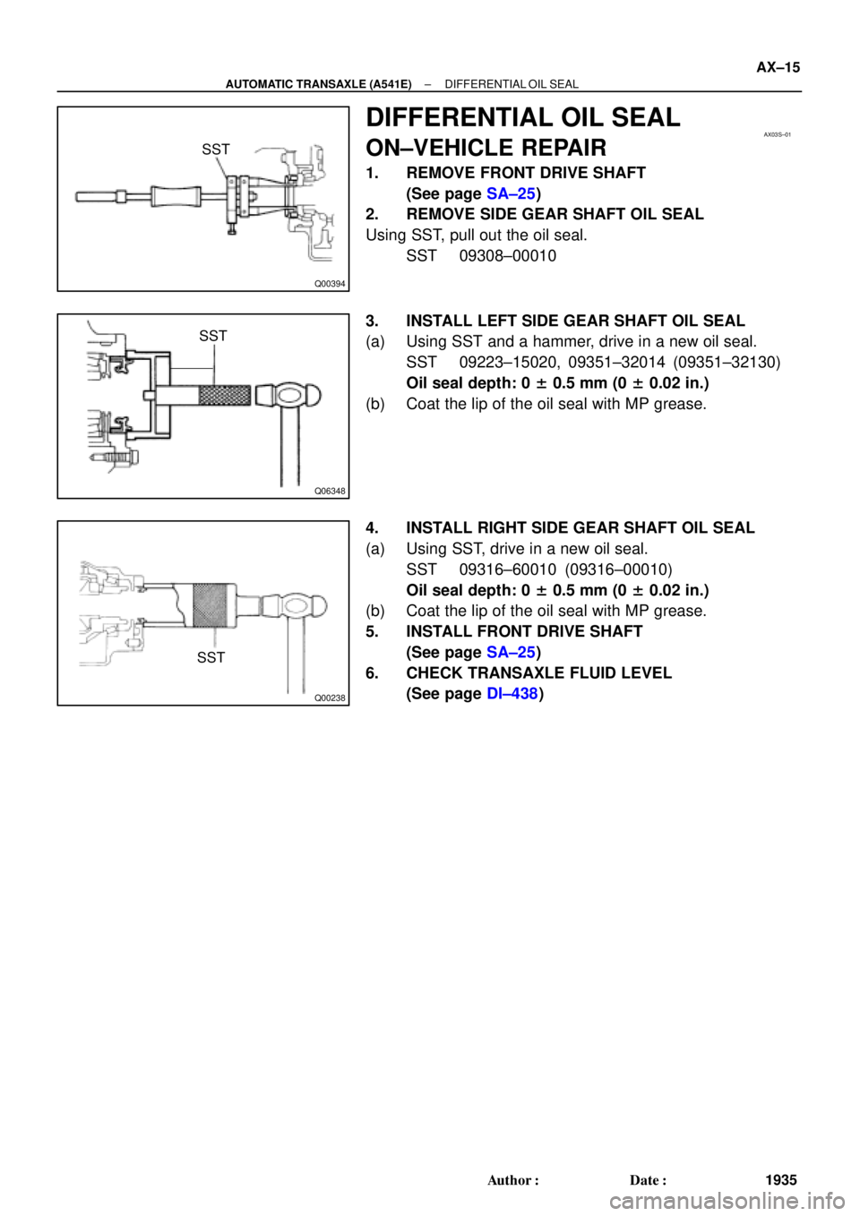
DIFFERENTIAL OIL SEAL
ON±VEHICLE REPAIR
1. REMOVE FRONT DRIVE SHAFT
(See page SA±25)
2. REMOVE SIDE GEAR SHAFT OIL SEAL
Using SST, pull out the oil seal.
SST 09308±00010
3. INSTALL LEFT SIDE GEAR SHAFT OIL SEAL
(a) Using SST and a hammer, drive in a new oil seal.
SST 09223±15020, 09351±32014 (09351±32130)
Oil seal depth: 0 ± 0.5 mm (0 ± 0.02 in.)
(b) Coat the lip of the oil seal with MP grease.
4. INSTALL RIGHT SIDE GEAR SHAFT OIL SEAL
(a) Using SST, drive in a new oil seal.
SST 09316±60010 (09316±00010)
Oil seal depth: 0 ± 0.5 mm (0 ± 0.02 in.)
(b) Coat the lip of the oil seal with MP grease.
5. INSTALL FRONT DRIVE SHAFT
(See page SA±25)
6. CHECK TRANSAXLE FLUID LEVEL
(See page DI±438)
Page 1952 of 4770
AUTOMATIC TRANSAXLE UNIT
1944 Author�: Date�:
12. REMOVE 2 FRONT SIDE ENGINE MOUNTING BOLTS
Torque:
TMC Made: 80 N´m (820 kgf´cm, 59")
Q06478
Q10286
Q06530
Q10038
AX±24
± AUTOMATIC TRANSAXLE (A541E)AUTOMATIC TRANSAXLE UNIT
1944 Author�: Date�:
12. REMOVE 2 FRONT SIDE ENGINE MOUNTING BOLTS
Torque:
TMC Made: 80 N´m (820 kgf´cm, 59 ft´lbf)
TMMK Made:
Green color bolt: 66 N´m (670 kgf´cm, 48 ft´lbf)
Silver color bolt: 44 N´m (440 kgf´cm, 32 ft´lbf)
13. REMOVE STARTER AND A/T SHIFT CABLE CLAMP
(a) Disconnect the connector and remove the nut.
(b) Remove the 2 bolts, starter and A/T shift cable clamp.
Torque: 39 N´m (400 kgf´cm, 29 ft´lbf)
14. REMOVE EXHAUST MANIFOLD BRACKET MOUNT-
ING BOLT
Torque:
Except California: 20 N´m (200 kgf´cm, 15 ft´lbf)
California: 34 N´m (350 kgf´cm, 25 ft´lbf)
15. REMOVE 5 TRANSAXLE±TO±ENGINE BOLTS AND
DISCONNECT GROUND TERMINAL
Torque: 66 N´m (670 kgf´cm, 48 ft´lbf)
16. REMOVE ENGINE HOOD
(a) Disconnect the washer pipe.
(b) Remove the 4 bolts and engine hood.
Torque: 26 N´m (265 kgf´cm, 19 ft´lbf)
17. RAISE AND SUPPORT VEHICLE SECURELY
18. REMOVE FRONT WHEELS
Torque: 103 N´m (1,050 kgf´cm, 76 ft´lbf)
19. REMOVE DIFFERENTIAL FLUID DRAIN PLUG AND
GASKET
HINT:
At the time of installation, please refer to the following item.
Replace the used gasket with a new gasket.
20. DRAIN DIFFERENTIAL FLUID
21. REMOVE LH AND RH ENGINE SIDE COVERS
22. REMOVE LH AND RH FRONT DRIVE SHAFTS
(See page SA±25)
 Using SST, install the bearing to the drive pinion")

Color
C0Inner
Outer47.5 (1.870)
16.3 (0.642)White
None
C173.6 (2.898)None
C251.8 (2.039)Yellow / Purp")