Page 3769 of 4770
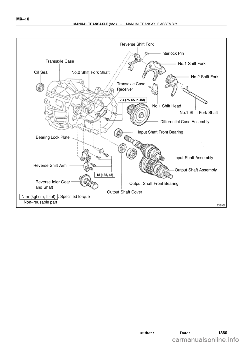
Z18962�Non±reusable part: Specified torque
N´m (kgf´cm, ft´lbf)Transaxle Case
No.2 Shift Fork ShaftReverse Shift Fork
Interlock Pin
No.1 Shift Fork
No.1 Shift Fork Shaft No.1 Shift Head
Differential Case Assembly
Input Shaft Front Bearing
Input Shaft Assembly
Output Shaft CoverOutput Shaft Front Bearing Reverse Idler Gear
and Shaft Reverse Shift ArmBearing Lock PlateTransaxle Case
Receiver Oil Seal
No.2 Shift Fork
Output Shaft Assembly �
�
�
7.4 (75, 65 in.´lbf)
18 (185, 13)
MX±10
± MANUAL TRANSAXLE (S51)MANUAL TRANSAXLE ASSEMBLY
1860 Author�: Date�:
Page 3773 of 4770
MANUAL TRANSAXLE ASSEMBLY
1864 Author�: Date�:
HINT:
At the time of installation, please refer to the following item.")
Q02682
SST
Q05785
x 5
Q05826
x 17
x 6
Q09474FIPG MX±14
± MANUAL TRANSAXLE (S51)MANUAL TRANSAXLE ASSEMBLY
1864 Author�: Date�:
HINT:
At the time of installation, please refer to the following item.
Using SST and a press, install the No.3 clutch hub assembly.
SST 09612±22011
(c) Remove the 5th gear.
15. REMOVE NEEDLE ROLLER BEARING
16. REMOVE REAR BEARING RETAINER
Remove the 5 bolts and retainer.
Sealant:
Part No.08833 ± 00070, THREE BOND 1324 or equiva-
lent
Torque: 42 N´m (430 kgf´cm, 31 ft´lbf)
17. REMOVE BEARING SNAP RING
Using a snap ring expander, remove the 2 snap rings.
HINT:
If it is difficult to remove and install the snap rings, pull up the
shafts.
18. REMOVE REVERSE IDLER GEAR SHAFT LOCK BOLT
AND GASKET
Torque: 29 N´m (300 kgf´cm, 22 ft´lbf)
19. REMOVE DIFFERENTIAL SIDE BEARING RETAINER
AND SHIM
Remove the 6 bolts, retainer and shim.
Sealant:
Part No.08833 ± 00080, THREE BOND 1344, LOCTITE
242 or equivalent
Torque: 18 N´m (185 kgf´cm, 13 ft´lbf)
20. REMOVE TRANSMISSION CASE
(a) Remove the 17 bolts.
Torque: 29 N´m (300 kgf´cm, 22 ft´lbf)
(b) Using a plastic hammer, tap the transmission case and re-
move it.
FIPG:
Part No. 08833 ± 00090, THREE BOND 1281 or equiva-
lent
Page 3774 of 4770
MANUAL TRANSAXLE ASSEMBLY
MX±15
1865 Author�: Date�:
21. REMOVE REVERSE IDLER GEAR AND SHAFT
(a) Pull out the shaft.
(b) Remove the idler gear and thrust washer")
Q05827
Q03065
± MANUAL TRANSAXLE (S51)MANUAL TRANSAXLE ASSEMBLY
MX±15
1865 Author�: Date�:
21. REMOVE REVERSE IDLER GEAR AND SHAFT
(a) Pull out the shaft.
(b) Remove the idler gear and thrust washer.
22. REMOVE REVERSE SHIFT ARM
(a) Shift the fork shaft into reverse.
(b) Remove the 2 bolts and pull off the reverse shift arm.
Torque: 18 N´m (185 kgf´cm, 13 ft´lbf)
23. REMOVE NO.1 SHIFT FORK SHAFT, NO.1 SHIFT
HEAD, NO.1 AND NO.2 SHIFT FORKS, REVERSE
SHIFT FORK WITH INTERLOCK PIN, INPUT AND OUT-
PUT SHAFTS ASSEMBLY
24. REMOVE DIFFERENTIAL CASE ASSEMBLY
25. REMOVE MAGNET FROM TRANSAXLE CASE
26. REMOVE NO.2 SHIFT FORK SHAFT
(a) Using a hexagon wrench, remove the straight screw plug.
Sealant:
Part No.08833 ± 00080, THREE BOND 1344, LOCTITE
242 or equivalent
Torque: 13 N´m (130 kgf´cm, 9 ft´lbf)
(b) Using a pin punch and hammer, drive out the slotted
spring pin.
(c) Pull out the shaft.
27. SEPARATE NO.1 SHIFT FORK SHAFT, NO.1 SHIFT
HEAD, NO.1, NO.2 SHIFT FORKS AND REVERSE
SHIFT FORK
(a) Mount the shift forks to the vise.
(b) Using a pin punch and hammer, drive out the slotted
spring pin from the No.1 fork shaft.
(c) Using a pin punch and hammer, drive out the slotted
spring pin from the No.1 fork shaft, as shown.
(d) Separate the No.1 shift fork shaft, No.1 shift head, No.1
and No.2 shift forks and reverse shift fork.
Page 3795 of 4770
MX04S±01
Z19302
Ring GearOuter Race and Side Bearing
Pinion Thrust Washer
Pinion Gear
Pinion Shaft
Side Gear
Side Gear Thrust Washer Side Bearing and Outer Race
Vehicle Speed Sensor Drive Gear Straight Pin Differential Case
Non±reusable partShim x 8�
83 (850, 61)
�Shim
�
N´m (kgf´cm, ft´lbf) : Specified torque MX±36
± MANUAL TRANSAXLE (S51)DIFFERENTIAL CASE
1886 Author�: Date�:
DIFFERENTIAL CASE
COMPONENTS
Page 3796 of 4770
DIFFERENTIAL CASE
MX±37
1887 Author�: Date�:
DISASSEMBLY
1. Vehicle Speed Sensor Drive Gear Side:
REMOVE SIDE BEARING FROM DIFFERENTIAL")
MX04T±01
Q08148
SST
Q04969
SST
AT2799
± MANUAL TRANSAXLE (S51)DIFFERENTIAL CASE
MX±37
1887 Author�: Date�:
DISASSEMBLY
1. Vehicle Speed Sensor Drive Gear Side:
REMOVE SIDE BEARING FROM DIFFERENTIAL
CASE
(a) Using SST, remove the bearing from the drive gear side
of the case.
SST 09950±00020, 09950±00030
(b) Remove the vehicle speed sensor drive gear.
2. REMOVE RING GEAR
(a) Place matchmarks on the ring gear and case.
(b) Remove the 8 bolts.
(c) Using a copper hammer, tap on the ring gear to remove
it from the case.
3. Ring Gear Side:
REMOVE SIDE BEARING FROM DIFFERENTIAL
CASE
Using SST, remove the bearing from the ring gear side of the
case.
SST 09950±00020, 09950±00030
4. INSPECT SIDE GEAR BACKLASH
Using a dial indicator, measure the backlash of one side gear
while holding one pinion toward the case.
Standard backlash:
0.05 ± 0.20 mm (0.0020 ± 0.0079 in.)
If the backlash is not within the specification, install the correct
thrust washer to the side gears.
5. DISASSEMBLE DIFFERENTIAL CASE
(a) Using a pin punch and hammer, drive out the straight pin.
(b) Remove the pinion shaft from the case.
(c) Remove the 2 pinions and side gears with the 4 thrust
washers from each gear.
Page 3797 of 4770
DIFFERENTIAL CASE
1888 Author�: Date�:
6. Transaxle Case Side:
IF NECESSARY, REPLACE DIFFERENTIAL SIDE
BEARING RETAIN")
Q08145
SST
SM0286
SST
SM0155
SST
Z00442
MT0634
SST MX±38
± MANUAL TRANSAXLE (S51)DIFFERENTIAL CASE
1888 Author�: Date�:
6. Transaxle Case Side:
IF NECESSARY, REPLACE DIFFERENTIAL SIDE
BEARING RETAINER OIL SEAL
(a) Using SST and a hammer, drive out the oil seal from the
retainer.
SST 09950±60020 (09951±00680), 09950±70010
(09951±07150)
(b) Using SST and a hammer, drive in a new oil seal until its
surface is flush with the case surface.
SST 09350±32014 (09351±32130, 09351±32150)
(c) Coat the lip of the oil seal with MP grease.
7. Transmission Case Side:
IF NECESSARY, REPLACE SIDE OIL SEAL
(a) Using a screwdriver and hammer, drive out the oil seal.
(b) Using SST and a hammer, drive in a new oil seal until its
surface is flush with the case surface.
SST 09350±32014 (09351±32130, 09351±32150)
(c) Coat the lip of the oil seal with MP grease.
8. Transaxle Case Side:
IF NECESSARY, REPLACE SIDE BEARING OUTER
RACE
(a) Using a brass bar and hammer, drive out the bearing out-
er race.
(b) Install the bearing retainer without an O±ring.
(c) Install and torque the 6 bolts.
Torque: 18 N´m (185 kgf´cm, 13 ft´lbf)
(d) Place the thinnest shim into the case.
(e) Using SST and a press, install a new bearing outer race.
SST 09950±60020 (09951±00680), 09950±70010
(09951±07150)
(f) Remove the 6 bolts.
(g) Remove the bearing retainer and shim.
Page 3798 of 4770
Q08184
SST
± MANUAL TRANSAXLE (S51)DIFFERENTIAL CASE
MX±39
1889 Author�: Date�:
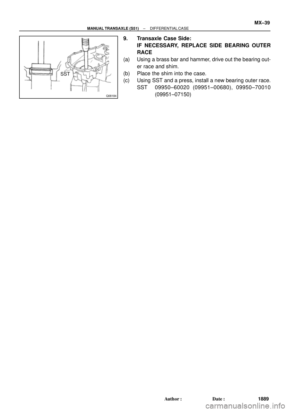
9. Transaxle Case Side:
IF NECESSARY, REPLACE SIDE BEARING OUTER
RACE
(a) Using a brass bar and hammer, drive out the bearing out-
er race and shim.
(b) Place the shim into the case.
(c) Using SST and a press, install a new bearing outer race.
SST 09950±60020 (09951±00680), 09950±70010
(09951±07150)
Page 3799 of 4770
DIFFERENTIAL CASE
1890 Author�: Date�:
REASSEMBLY
1. ASSEMBLE DIFFERENTIAL CASE
(a) Install the correct thrust washers and side gears. Refer to")
MX04U±01
AT2981
Q08147
MX±40
± MANUAL TRANSAXLE (S51)DIFFERENTIAL CASE
1890 Author�: Date�:
REASSEMBLY
1. ASSEMBLE DIFFERENTIAL CASE
(a) Install the correct thrust washers and side gears. Refer to
the table below, select thrust washers which will ensure
that the backlash is within the specification. Try to select
washers of the same size for both sides.
Standard backlash:
0.05 ± 0.20 mm (0.0020 ± 0.0079 in.)
Thickness mm (in.)Thickness mm (in.)
0.95 (0.0374)1.10 (0.0433)
1.00 (0.0394)1.15 (0.0453)
1.05 (0.0413)1.20 (0.0472)
Install the thrust washers and side gears in the differential
case.
(b) Install the pinion shaft.
(c) Inspect the side gear backlash.
Using a dial indicator, measure the side gear backlash
while holding one pinion gear toward the case.
Standard backlash:
0.05 ± 0.20 mm (0.0020 ± 0.0079 in.)
If the backlash is not within the specification, install a thrust
washer of different thickness.
(d) Using a pin punch and hammer, drive in the straight pin
through the case and hole in the pinion shaft.
(e) Stake the differential case.
2. INSTALL RING GEAR ON DIFFERENTIAL CASE
(a) Clean the contact surface of the differential case and the
threads of the ring gear and differential case.
(b) Heat the ring gear in boiling water.
(c) Carefully take the ring gear out of the water.
(d) After moisture on the ring gear has completely evapo-
rated, quickly install the ring gear to the differential case.
HINT:
Align the matchmarks on the differential case and the ring gear.
(e) Temporarily install the 8 bolts.
NOTICE:
The ring gear set bolts should not be torqued until the ring
gear has cooled sufficiently.
(f) After the ring gear has cooled sufficiently, torque the ring
gear set bolts.
Torque: 83 N´m (850 kgf´cm, 61 ft´lbf)