Page 3800 of 4770
DIFFERENTIAL CASE
MX±41
1891 Author�: Date�:
3. INSTALL SIDE BEARING TO DIFFERENTIAL CASE
(a) Using SST and a press, install a new side")
SM0287
SST
Q08649
Case Side
SM0289
SST
± MANUAL TRANSAXLE (S51)DIFFERENTIAL CASE
MX±41
1891 Author�: Date�:
3. INSTALL SIDE BEARING TO DIFFERENTIAL CASE
(a) Using SST and a press, install a new side bearing to the
transmission case side.
SST 09316±60011 (09316±00011), 09350±32014
(09351±32120)
(b) Install the vehicle speed sensor drive gear to the trans-
axle case side.
(c) Using SST and a press, install a new side bearing to the
transaxle case side.
SST 09316±60011 (09316±00011), 09350±32014
(09351±32120)
NOTICE:
Install the black cage bearing on the vehicle speed sensor
drive gear side.
4. ADJUST DIFFERENTIAL CASE SIDE BEARING PRE-
LOAD
(a) Install the differential to the transaxle case.
(b) Install the transmission case.
(c) Install and torque the case bolts.
Torque: 29 N´m (300 kgf´cm, 22 ft´lbf)
(d) Install the shim into the transmission case.
(e) Install the bearing retainer without an O±ring.
(f) Install and torque the 6 bolts.
Torque: 18 N´m (185 kgf´cm, 13 ft´lbf)
Page 3801 of 4770
Z00620
SST MX±42
± MANUAL TRANSAXLE (S51)DIFFERENTIAL CASE
1892 Author�: Date�:
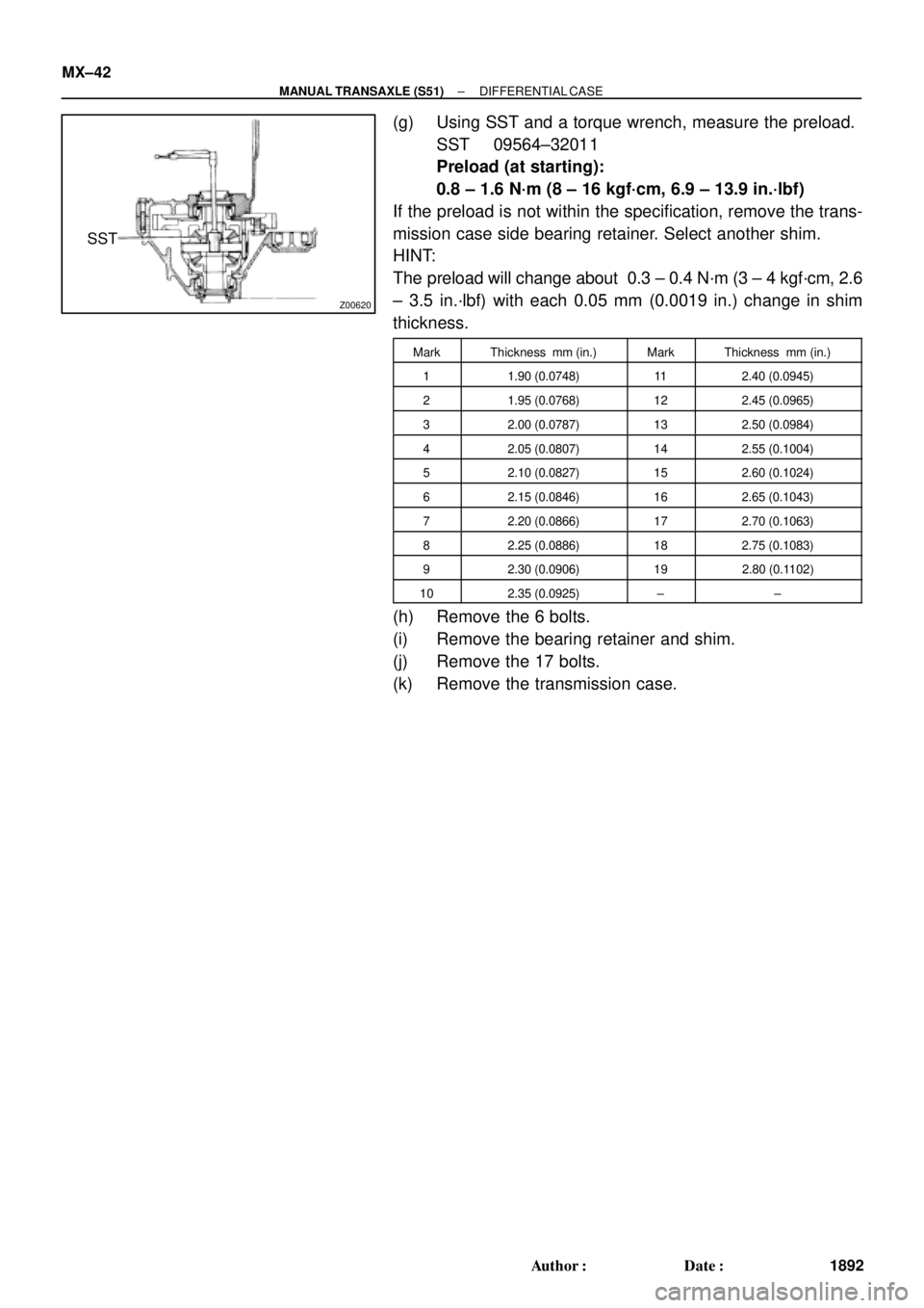
(g) Using SST and a torque wrench, measure the preload.
SST 09564±32011
Preload (at starting):
0.8 ± 1.6 N´m (8 ± 16 kgf´cm, 6.9 ± 13.9 in.´lbf)
If the preload is not within the specification, remove the trans-
mission case side bearing retainer. Select another shim.
HINT:
The preload will change about 0.3 ± 0.4 N´m (3 ± 4 kgf´cm, 2.6
± 3.5 in.´lbf) with each 0.05 mm (0.0019 in.) change in shim
thickness.
MarkThickness mm (in.)MarkThickness mm (in.)
11.90 (0.0748)112.40 (0.0945)
21.95 (0.0768)122.45 (0.0965)
32.00 (0.0787)132.50 (0.0984)
42.05 (0.0807)142.55 (0.1004)
52.10 (0.0827)152.60 (0.1024)
62.15 (0.0846)162.65 (0.1043)
72.20 (0.0866)172.70 (0.1063)
82.25 (0.0886)182.75 (0.1083)
92.30 (0.0906)192.80 (0.1102)
102.35 (0.0925)±±
(h) Remove the 6 bolts.
(i) Remove the bearing retainer and shim.
(j) Remove the 17 bolts.
(k) Remove the transmission case.
Page 3812 of 4770
MX052±02
Z19124
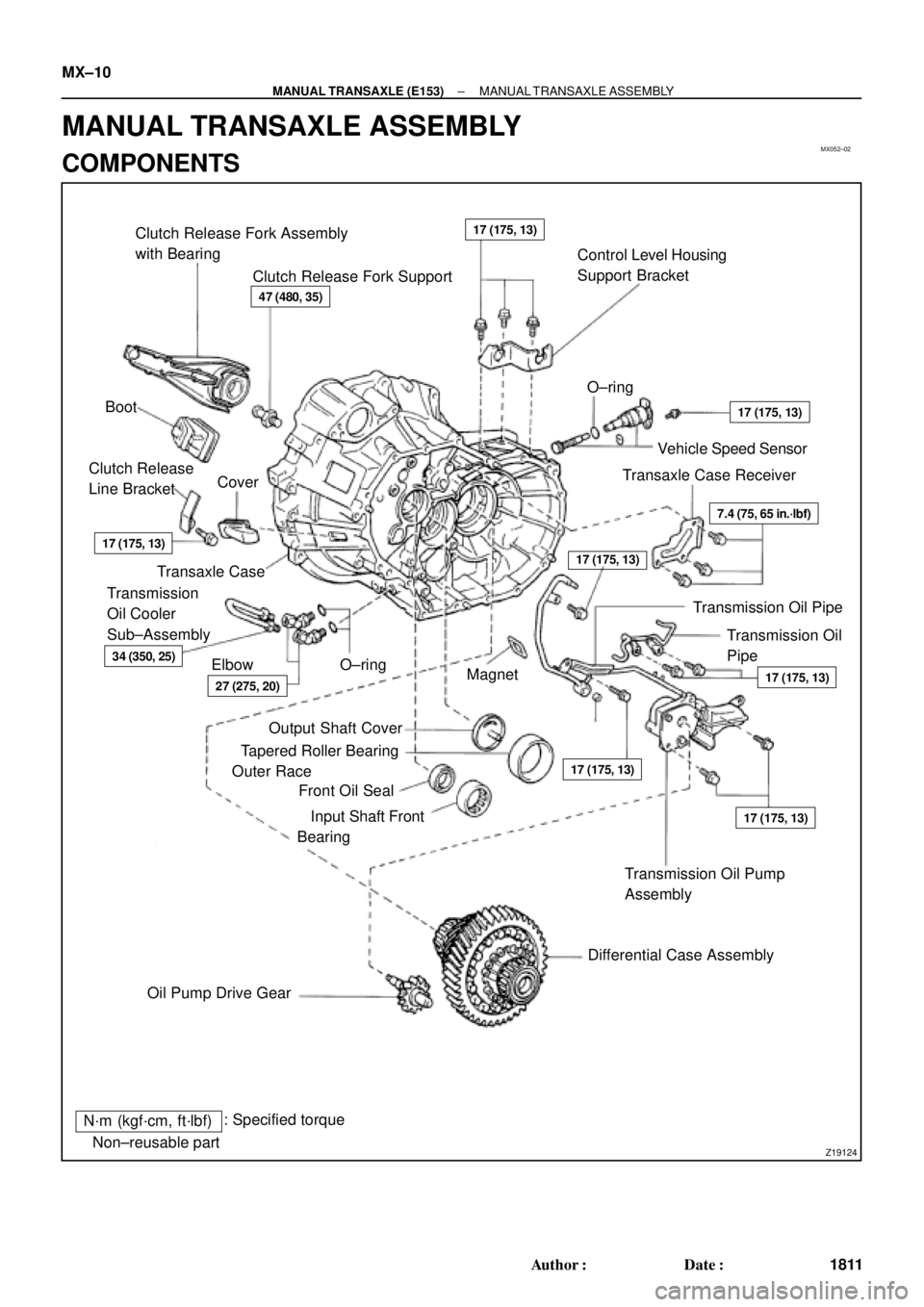
Clutch Release Fork Assembly
with Bearing
Clutch Release Fork SupportControl Level Housing
Support Bracket
Boot�O±ring
Vehicle Speed Sensor
Transaxle Case Receiver Clutch Release
Line BracketCover
Transaxle Case
Transmission Oil
Pipe Transmission
Oil Cooler
Sub±Assembly
Elbow�O±ring
Magnet
�
Transmission Oil Pump
Assembly
Differential Case Assembly
Oil Pump Drive Gear�Output Shaft Cover
�Tapered Roller Bearing
Outer Race
�Front Oil Seal
�Input Shaft Front
Bearing
N´m (kgf´cm, ft´lbf): Specified torque
�Non±reusable part
47 (480, 35)
17 (175, 13)
17 (175, 13)
17 (175, 13)
17 (175, 13)
17 (175, 13)
7.4 (75, 65 in.´lbf)
17 (175, 13)
27 (275, 20)
34 (350, 25)
17 (175, 13)
Transmission Oil Pipe MX±10
± MANUAL TRANSAXLE (E153)MANUAL TRANSAXLE ASSEMBLY
1811 Author�: Date�:
MANUAL TRANSAXLE ASSEMBLY
COMPONENTS
Page 3820 of 4770
MANUAL TRANSAXLE ASSEMBLY
1819 Author�: Date�:
32. REMOVE INPUT AND OUTPUT SHAFTS ASSEMBLY
(a) Leaning the output shaft to the differential side, remove
the inp")
MT0781
MX±18
± MANUAL TRANSAXLE (E153)MANUAL TRANSAXLE ASSEMBLY
1819 Author�: Date�:
32. REMOVE INPUT AND OUTPUT SHAFTS ASSEMBLY
(a) Leaning the output shaft to the differential side, remove
the input shaft assembly.
(b) Lift up the differential case assembly, remove the output
shaft assembly.
33. REMOVE DIFFERENTIAL CASE ASSEMBLY
(a) Remove the oil pump drive gear.
(b) Remove the differential case assembly.
34. REMOVE MAGNET FROM TRANSAXLE CASE
35. REMOVE TRANSMISSION OIL PUMP ASSEMBLY
AND OIL PIPE
(a) Remove the 2 bolts and oil pipe.
Torque: 17 N´m (175 kgf´cm, 13 ft´lbf)
(b) Remove the 2 bolts and oil pump assembly.
Torque: 17 N´m (175 kgf´cm, 13 ft´lbf)
36. REMOVE NO.5 SYNCHRONIZER RING WITH KEY
SPRING FROM NO.3 CLUTCH HUB
(a) Remove the No.5 synchronizer ring with the key spring
from the No.3 clutch hub.
(b) Using a screwdriver, remove the snap ring.
HINT:
Wrap vinyl tape on the screwdriver to prevent damaging the
synchronizer ring.
(c) Remove the synchronizer rings.
Page 3844 of 4770
MX05H±01
Z17560
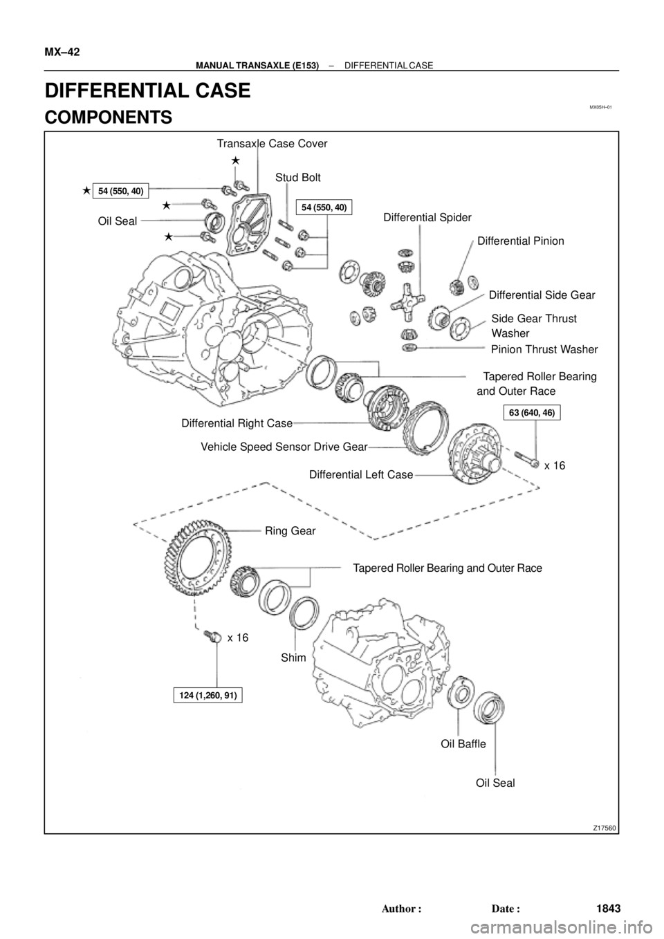
Transaxle Case Cover
Stud Bolt �
54 (550, 40)
�54 (550, 40)
�
�Oil Seal
�Differential Spider
Differential Pinion
Differential Side Gear
Side Gear Thrust
Washer
Pinion Thrust Washer
�Tapered Roller Bearing
and Outer Race
63 (640, 46)
x 16 Differential Right Case
Vehicle Speed Sensor Drive Gear
Differential Left Case
Ring Gear
x 16�Tapered Roller Bearing and Outer Race
Shim
124 (1,260, 91)
Oil Baffle
�Oil Seal MX±42
± MANUAL TRANSAXLE (E153)DIFFERENTIAL CASE
1843 Author�: Date�:
DIFFERENTIAL CASE
COMPONENTS
Page 3845 of 4770
DIFFERENTIAL CASE
MX±43
1844 Author�: Date�:
DISASSEMBLY
1. REMOVE TAPERED ROLLER BEARING
Using SST, remove the left and")
MX05I±03
Q05166
SST
Z00281
Matchmarks
Z00284
Z00286
± MANUAL TRANSAXLE (E153)DIFFERENTIAL CASE
MX±43
1844 Author�: Date�:
DISASSEMBLY
1. REMOVE TAPERED ROLLER BEARING
Using SST, remove the left and right bearings.
SST 09950±40011
2. REMOVE RING GEAR
(a) Place matchmarks on both the differential case and ring
gear.
(b) Remove the 16 bolts.
(c) Using a plastic hammer, tap the ring gear and remove it.
3. DISASSEMBLE DIFFERENTIAL CASE
(a) Place matchmarks on the differential right and left cases.
(b) Using a torx wrench (T50), remove the 16 torx screws.
(c) Using a plastic hammer, tap the differential left case.
(d) Remove the vehicle speed sensor drive gear from the dif-
ferential right case.
(e) Remove the 2 differential side gears, side gear thrust
washers, 4 differential pinions and pinion thrust washers
from the differential left case.
4. Transmission Case Side:
IF NECESSARY, REPLACE OIL SEAL AND TAPERED
ROLLER BEARING OUTER RACE
(a) Using a screwdriver, remove the oil seal.
(b) Remove the oil baffle.
(c) Using a brass bar and hammer, drive out the bearing out-
er race lightly and evenly.
(d) Remove the shim.
(e) Install the shim. (See page MX±42)
HINT:
First select and install a shim of less thickness than before.
Page 3846 of 4770
Z00288
SST
Z00289
Q06288
SST
MT0659
Z01427
SST MX±44
± MANUAL TRANSAXLE (E153)DIFFERENTIAL CASE
1845 Author�: Date�:
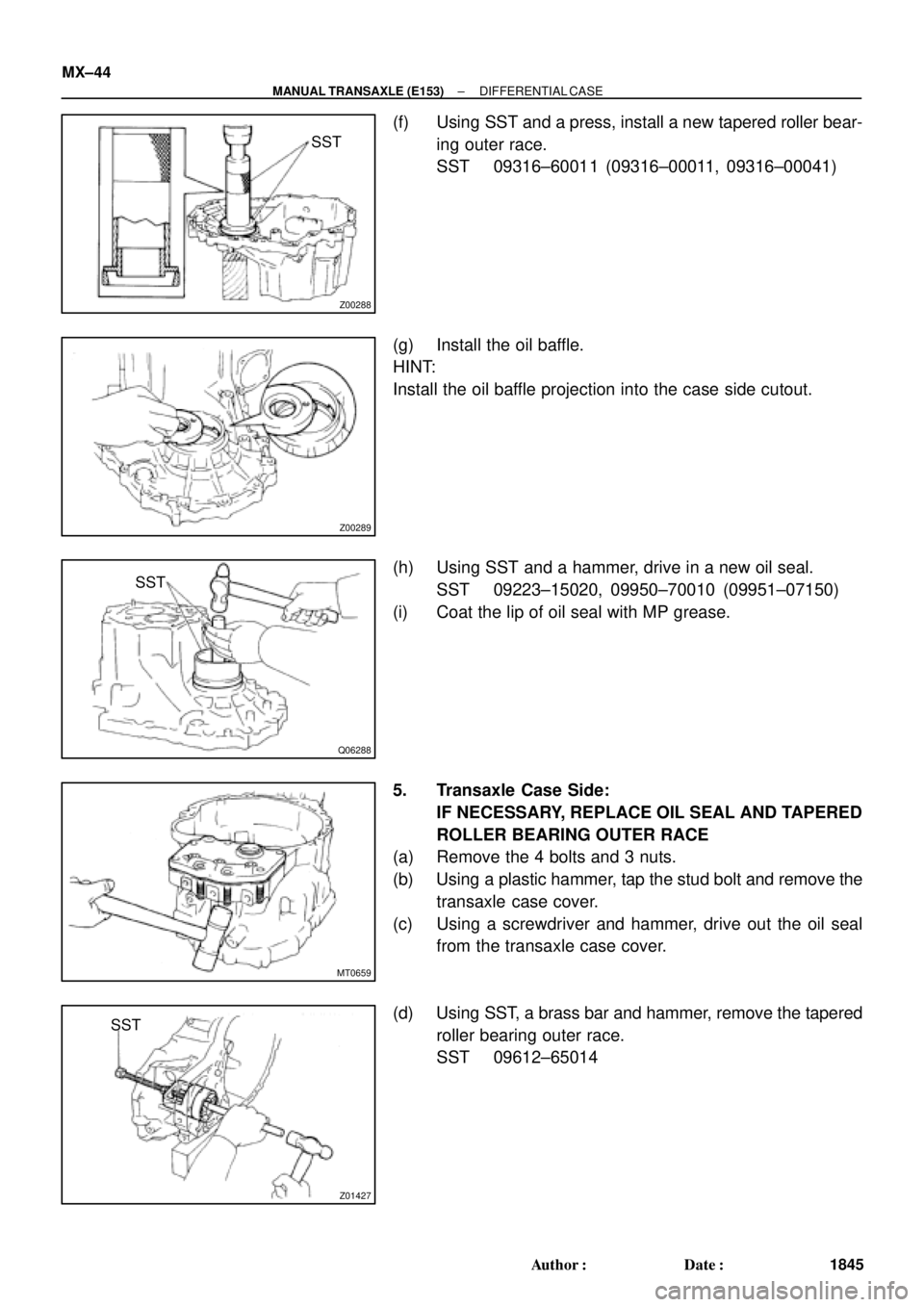
(f) Using SST and a press, install a new tapered roller bear-
ing outer race.
SST 09316±60011 (09316±00011, 09316±00041)
(g) Install the oil baffle.
HINT:
Install the oil baffle projection into the case side cutout.
(h) Using SST and a hammer, drive in a new oil seal.
SST 09223±15020, 09950±70010 (09951±07150)
(i) Coat the lip of oil seal with MP grease.
5. Transaxle Case Side:
IF NECESSARY, REPLACE OIL SEAL AND TAPERED
ROLLER BEARING OUTER RACE
(a) Remove the 4 bolts and 3 nuts.
(b) Using a plastic hammer, tap the stud bolt and remove the
transaxle case cover.
(c) Using a screwdriver and hammer, drive out the oil seal
from the transaxle case cover.
(d) Using SST, a brass bar and hammer, remove the tapered
roller bearing outer race.
SST 09612±65014
Page 3847 of 4770
Z00292
SST
Z00293
SST
Z19038
FIPGF
± MANUAL TRANSAXLE (E153)DIFFERENTIAL CASE
MX±45
1846 Author�: Date�:
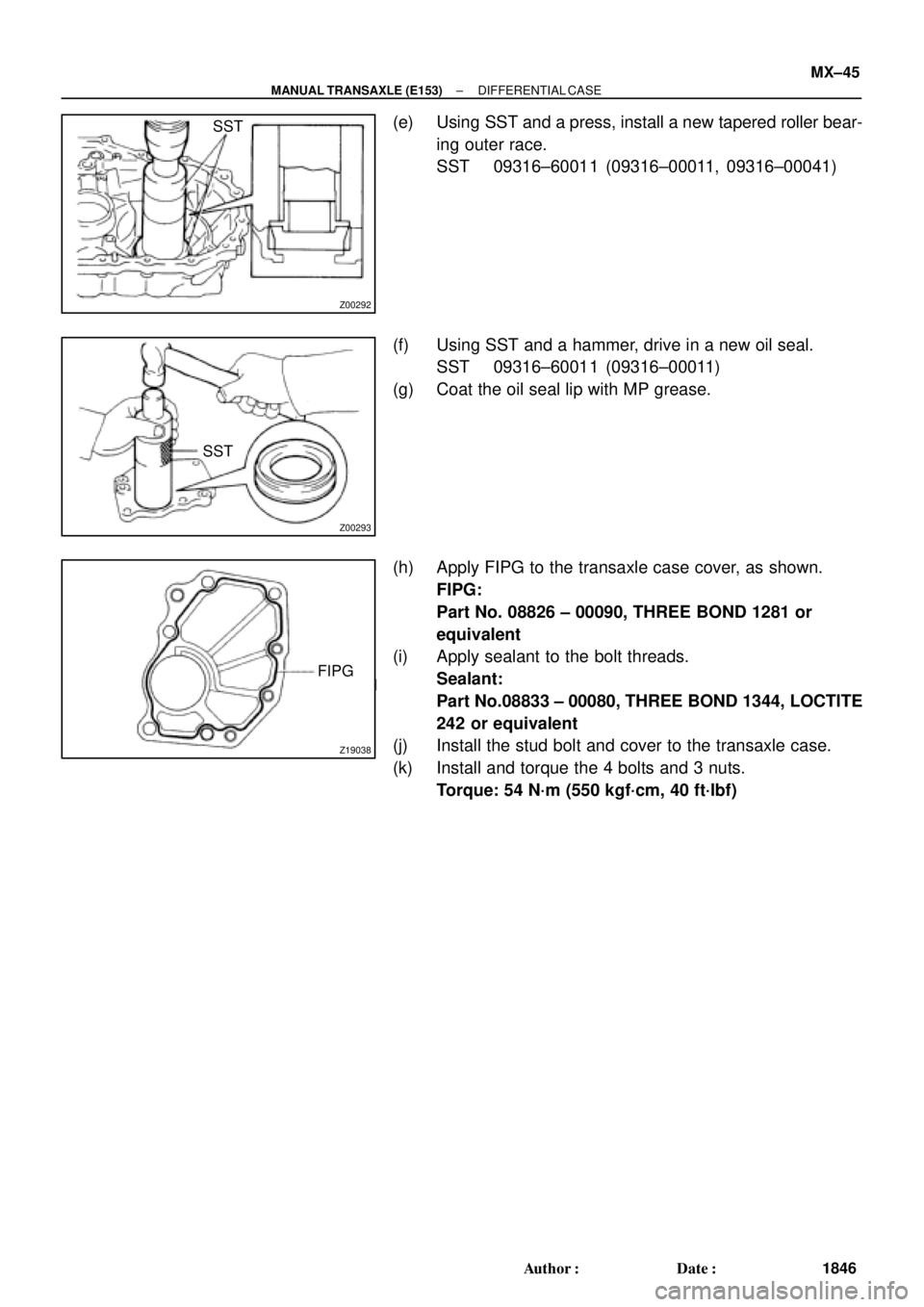
(e) Using SST and a press, install a new tapered roller bear-
ing outer race.
SST 09316±60011 (09316±00011, 09316±00041)
(f) Using SST and a hammer, drive in a new oil seal.
SST 09316±60011 (09316±00011)
(g) Coat the oil seal lip with MP grease.
(h) Apply FIPG to the transaxle case cover, as shown.
FIPG:
Part No. 08826 ± 00090, THREE BOND 1281 or
equivalent
(i) Apply sealant to the bolt threads.
Sealant:
Part No.08833 ± 00080, THREE BOND 1344, LOCTITE
242 or equivalent
(j) Install the stud bolt and cover to the transaxle case.
(k) Install and torque the 4 bolts and 3 nuts.
Torque: 54 N´m (550 kgf´cm, 40 ft´lbf)