Page 1729 of 4770
AUTOMATIC TRANSAXLEDIFFERENTIAL ASSEMBLY ±
AX±96
(b) Measure the oil seal press in depth.
Oil seal press in depth:
4 mm (0.16 in.)
(c) With the oil seal lip facing upward, use SST to press in a
new oil seal until its end is flush with the surface of the
cage.
SST 09350±32014 (09351±32090)
(d) Coat the oil seal lip with MP grease.
3. INSTALL SHAFT BEARING OUTER RACE TO CAGE
Using SST, press a new outer race into the cage.
SST 09350±32014 (09351±32111, 09351±32130)
4. INSTALL DRIVE PINION SHAFT BEARING
Using SST, press in the bearing.
SST 09350±32014 (09351±32100)
5. PLACE BEARING CAGE ONTO DRIVE PINION SHAFT
Be careful not to damage the oil seal with the splines.
Page 1730 of 4770
AUTOMATIC TRANSAXLEDIFFERENTIAL ASSEMBLY ±
AX±97
DIFFERENTIAL SIDE BEARING PRELOAD
ADJUSTMENT
1. PLACE OUTER RACE AND ADJUSTING SHIM ONTO
RH SIDE BEARING
Use the adjusting shim which was removed or one 2.40
mm (0.0945 in.) thick.
2. PLACE DIFFERENTIAL CASE INTO TRANSAXLE
CASE
Be sure to install the adjusting shim.
3. INSTALL LH BEARING RETAINER
(a) Do not install the O±ring yet.
(b) Do not coat the bolt threads with sealant yet.
(c) Temporarily tighten the bolts evenly and gradually while
turning the ring gear.
4. INSTALL RH SIDE BEARING CAP
Tighten the bolts evenly and gradually while turning the
ring gear.
Torque: 72 N´m (730 kgf´cm, 53 ft´lbf)
5. TIGHTEN LH BEARING RETAINER
Torque: 19 N´m (195 kgf´cm, 14 ft´lbf)
AX0GL±02
Page 1731 of 4770
:
New bearin")
AUTOMATIC TRANSAXLEDIFFERENTIAL ASSEMBLY ±
AX±98
6. ADJUST SIDE BEARING PRELOAD
Using SST and a torque meter, measure the preload of
the ring gear.
SST 09564±32011
Preload (at starting):
New bearing
1.0 ± 1.6 N´m (10 ± 16 kgf´cm, 8.7 ± 13.9 in.´lbf)
Reused bearing
0.5 ± 0.8 N´m (5 ± 8 kgf´cm, 4.3 ± 6.9 in.´lbf)
If the preload is not within specification, remove the differ-
ential case assembly.
Reselect the RH adjusting shim.
mm (in.)
ThicknessThickness
1.90 (0.0748)2.40 (0.0945)
1.95 (0.0786)2.45 (0.0965)
2.00 (0.0787)2.50 (0.0984)
2.05 (0.0807)2.55 (0.1004)
2.10 (0.0827)2.60 (0.1024)
2.15 (0.0846)2.65 (0.1043)
2.20 (0.0866)2.70 (0.1063)
2.25 (0.0886)2.75 (0.1083)
2.30 (0.0906)2.80 (0.1103)
HINT: The preload will change by about 0.3 ± 0.4 N´m (3
± 4kgf´cm, 2.6 ± 3.5 in.´lbf) with a change in shim thick-
ness of 0.05 mm (0.0020 in.).
7. REMOVE DIFFERENTIAL CASE AND COMPONENT
PARTS
If the preload is adjusted within specification, remove the
bearing retainer, differential case, RH side bearing and
shim.
Be careful not to lose the adjusting shim.
Page 1737 of 4770
AUTOMATIC TRANSAXLECOMPONENT PARTS INSTALLATION ±
AX±104
�If the preload is greater than specified, replace the
bearing spacer.
�If the preload is less than specified, retighten the nut
13 N´m (130 kgf´cm, 9 ft´lbf) at a time until the speci-
fied preload is reached.
If the maximum torque is exceeded while retightening the
nut, replace the bearing spacer and repeat the preload
procedure.
Do not back off the nut to reduce the preload.
Maximum torque:
289 N´m (2,950 kgf´cm, 213 ft´lbf)
(e) If the preload is adjusted within specification, make a note
of it.
DIFFERENTIAL INSTALLATION
1. PLACE OUTER RACE AND SELECTED ADJUSTING
SHIM ONTO RH SIDE BEARING
2. PLACE DIFFERENTIAL CASE INTO CASE
Be sure to install the adjusting shim into place.
3. INSTALL LH BEARING RETAINER
(a) Install a new O±ring.
(b) Position the retainer by tapping it while holding the differ-
ential case center with the retainer.
(c) Clean the threads of the bolts and case with white gaso-
line.
AX0SX±01
Page 1769 of 4770
Q00394
SST
AX03B±01
Q00247
SST
± AUTOMATIC TRANSAXLE (A140E)DIFFERENTIAL OIL SEAL
AX±11
1904 Author�: Date�:
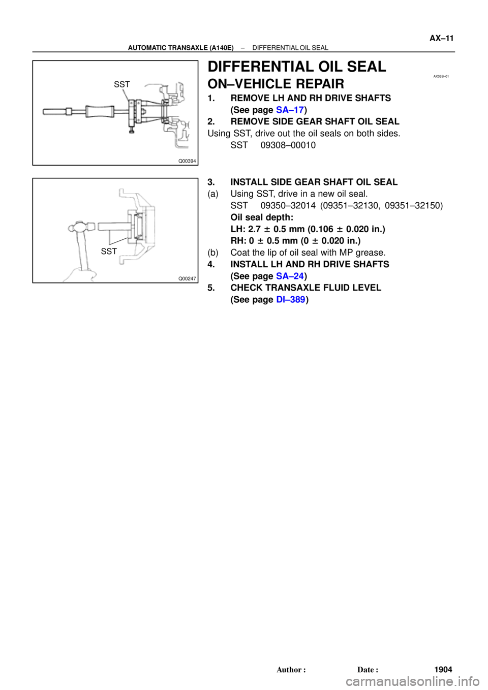
DIFFERENTIAL OIL SEAL
ON±VEHICLE REPAIR
1. REMOVE LH AND RH DRIVE SHAFTS
(See page SA±17)
2. REMOVE SIDE GEAR SHAFT OIL SEAL
Using SST, drive out the oil seals on both sides.
SST 09308±00010
3. INSTALL SIDE GEAR SHAFT OIL SEAL
(a) Using SST, drive in a new oil seal.
SST 09350±32014 (09351±32130, 09351±32150)
Oil seal depth:
LH: 2.7 ± 0.5 mm (0.106 ± 0.020 in.)
RH: 0 ± 0.5 mm (0 ± 0.020 in.)
(b) Coat the lip of oil seal with MP grease.
4. INSTALL LH AND RH DRIVE SHAFTS
(See page SA±24)
5. CHECK TRANSAXLE FLUID LEVEL
(See page DI±389)
Page 1778 of 4770
AUTOMATIC TRANSAXLE UNIT
1913 Author�: Date�:
14. REMOVE EXHAUST MANIFOLD STAY
Remove the 2 bolts and exhaust manifold stay.
Torque: 42 N´m (")
Q10058
Q10059
Q00251
AX±20
± AUTOMATIC TRANSAXLE (A140E)AUTOMATIC TRANSAXLE UNIT
1913 Author�: Date�:
14. REMOVE EXHAUST MANIFOLD STAY
Remove the 2 bolts and exhaust manifold stay.
Torque: 42 N´m (430 kgf´cm, 31 ft´lbf)
15. REMOVE TRANSAXLE±TO±ENGINE BOLT
Torque: 66 N´m (670 kgf´cm, 48 ft´lbf)
16. REMOVE ENGINE HOOD
(a) Disconnect the washer pipe.
(b) Remove the 4 bolts and engine hood.
Torque: 14 N´m (145 kgf´cm, 10 ft´lbf)
17. RAISE AND SUPPORT VEHICLE SECURELY
18. REMOVE FRONT WHEELS
Torque: 103 N´m (1,050 kgf´cm, 76 ft´lbf)
19. REMOVE ENGINE UNDER COVER AND CENTER EN-
GINE UNDER COVER
20. DISCONNECT SHIFT CONTROL CABLE
(a) Remove the nut and disconnect the shift control cable
from the park/neutral position switch.
Torque: 15 N´m (150 kgf´cm, 11 ft´lbf)
(b) Remove the clip and disconnect the shift control cable
from the bracket.
21. REMOVE DIFFERENTIAL FLUID DRAIN PLUG AND
GASKET
HINT:
At the time of installation, please refer to the following item.
Replace the used gasket with a new gasket.
22. DRAIN DIFFERENTIAL FLUID
23. REMOVE LH AND RH FENDER APRON SEALS
24. REMOVE LH AND RH DRIVE SHAFTS
(See page SA±17)
Page 1792 of 4770

IATIntake Air TemperatureIntake or Inlet Air Temperature
ICMIgnition Control Module±
IFIIndirect Fuel")
INTRODUCTIONGLOSSARY OF SAE AND TOYOTA TERMS ±
IN±7
IACIdle Air ControlIdle Speed Control (ISC)
IATIntake Air TemperatureIntake or Inlet Air Temperature
ICMIgnition Control Module±
IFIIndirect Fuel InjectionIndirect Injection
IFSInertia Fuel±Shutoff±
ISCIdle Speed Control±
KSKnock SensorKnock Sensor
MAFMass Air FlowAir Flow Meter
MAPManifold Absolute PressureManifold Pressure
Intake Vacuum
MCMixture Control
Electric Bleed Air Control Valve (EBCV)
Mixture Control Valve (MCV)
Electric Air Control Valve (EACV)
MDPManifold Differential Pressure±
MFIMultiport Fuel InjectionElectronic Fuel Injection (EFI)
MILMalfunction Indicator LampCheck Engine Light
MSTManifold Surface Temperature±
MVZManifold Vacuum Zone±
NVRAMNon±Volatile Random Access Memory±
O2SOxygen SensorOxygen Sensor, O2 Sensor (O2S)
OBDOn±Board DiagnosticOn±Board Diagnostic (OBD)
OCOxidation Catalytic ConverterOxidation Catalyst Converter (OC), CCo
OPOpen LoopOpen Loop
PAIRPulsed Secondary Air InjectionAir Suction (AS)
PCMPowertrain Control Module±
PNPPark/Neutral Position±
PROMProgrammable Read Only Memory±
PSPPower Steering Pressure±
PTOXPeriodic Trap OxidizerDiesel Particulate Filter (DPF)
Diesel Particulate Trap (DPT)
RAMRandom Access MemoryRandom Access Memory (RAM)
RMRelay Module±
ROMRead Only MemoryRead Only Memory (ROM)
RPMEngine SpeedEngine Speed
SCSuperchargerSupercharger
SCBSupercharger Bypass±
SFISequential Multiport Fuel InjectionElectronic Fuel Injection (EFI), Sequential Injection
SPLSmoke Puff Limiter±
SRIService Reminder Indicator±
SRTSystem Readiness Test±
STScan Tool±
TBThrottle BodyThrottle Body
TBIThrottle Body Fuel InjectionSingle Point Injection
Central Fuel Injection (Ci)
TCTurbochargerTurbocharger
TCCTorque Converter ClutchTorque Converter
TCMTransmission Control ModuleTransmission ECU (Electronic Control Unit)
TPThrottle PositionThrottle Position
TRTransmission Range±
Page 1803 of 4770
AUTOMATIC TRANSAXLEPREPARATION ±
AX±7
(09351±32100)Drive Pinion Bearing Replacer
(09351±32120)Overdrive Bearing Replacer
(09351±32140)Oil Seal Replacer
(09351±32150)Oil Seal Replacer
(09351±32190)Measure Terminal
(09351±32200)No.3 Piston Spring Compressor
09608±16011Rear Hub Bearing Tool±Remove differential side bearing
09612±65014Steering Worm Bearing PullerRemove pinion shaft bearing outer
race
09950±40010Puller B Set
RECOMMENDED COOL
09031±00030Pin Punch .
AX02M±02
 Measure the oil seal press in depth.
Oil seal press in depth:
4 mm (0.16 in.)
(c) With the oil seal lip facing upward, use SST to press in a
new")


Drive Pinion Bearing Replacer
(09351±32120)Overdrive Bearing Replacer
(09351±32140)Oil Seal Replacer
(09351±32150)Oil Seal Replacer
(09351±321")