Page 1591 of 4592
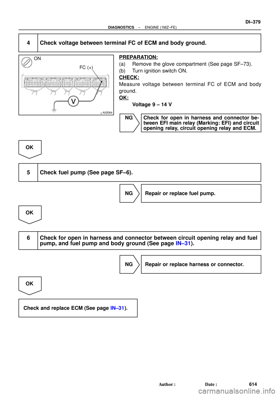
A02064
ON
FC (+)
± DIAGNOSTICSENGINE (1MZ±FE)
DI±379
614 Author�: Date�:
4 Check voltage between terminal FC of ECM and body ground.
PREPARATION:
(a) Remove the glove compartment (See page SF±73).
(b) Turn ignition switch ON.
CHECK:
Measure voltage between terminal FC of ECM and body
ground.
OK:
Voltage 9 ± 14 V
NG Check for open in harness and connector be-
tween EFI main relay (Marking: EFI) and circuit
opening relay, circuit opening relay and ECM.
OK
5 Check fuel pump (See page SF±6).
NG Repair or replace fuel pump.
OK
6 Check for open in harness and connector between circuit opening relay and fuel
pump, and fuel pump and body ground (See page IN±31).
NG Repair or replace harness or connector.
OK
Check and replace ECM (See page IN±31).
Page 1593 of 4592
A00307
ON
VSV is ON VSV is OFF
Air Filter Air
Air
E
FE
F
BE6653
FI7073 FI7074
Air Filter
± DIAGNOSTICSENGINE (1MZ±FE)
DI±381
616 Author�: Date�:
INSPECTION PROCEDURE
TOYOTA hand±held tester
1 Connect TOYOTA hand±held tester and check operation of VSV for ACIS.
PREPARATION:
(a) Remove the fuse cover on the instrument panel.
(b) Connect the TOYOTA hand±held tester to the DLC3.
(c) Turn the ignition switch ON and push the TOYOTA hand±
held tester main switch ON.
(d) Select the ACTIVE TEST mode on the TOYOTA hand±
held tester.
CHECK:
Check operation of VSV when VSV is operated by the TOYOTA
hand±held tester.
OK:
VSV is ON:
Air from pipe E is flowing out through pipe F.
VSV is OFF:
Air from pipe E is flowing out through the air filter.
OK Check for vacuum tank (See page SF±51).
NG
2 Check VSV for ACIS (See page SF±60).
NG Replace VSV for ACIS.
OK
Page 1594 of 4592
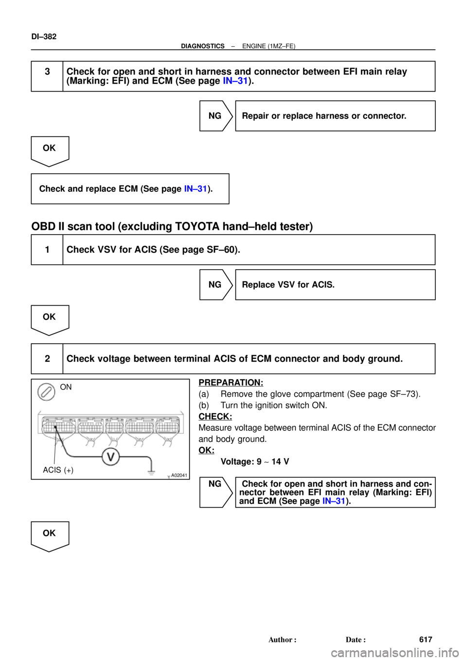
A02041
ON
ACIS (+)
DI±382
± DIAGNOSTICSENGINE (1MZ±FE)
617 Author�: Date�:
3 Check for open and short in harness and connector between EFI main relay
(Marking: EFI) and ECM (See page IN±31).
NG Repair or replace harness or connector.
OK
Check and replace ECM (See page IN±31).
OBD II scan tool (excluding TOYOTA hand±held tester)
1 Check VSV for ACIS (See page SF±60).
NG Replace VSV for ACIS.
OK
2 Check voltage between terminal ACIS of ECM connector and body ground.
PREPARATION:
(a) Remove the glove compartment (See page SF±73).
(b) Turn the ignition switch ON.
CHECK:
Measure voltage between terminal ACIS of the ECM connector
and body ground.
OK:
Voltage: 9 ~ 14 V
NG Check for open and short in harness and con-
nector between EFI main relay (Marking: EFI)
and ECM (See page IN±31).
OK
Page 1596 of 4592

A07453
5
1B±R
1ECM Engine Room J/B
E77
STA
E1 S2
Starter W±B 9 5
2D
2K 3
2
Sarter Relay MAIN
2B3
2J 11 B
J7
J7 J8
Junction
Connector CB
B II210 From Battery
W±B
W±B
A
A J11
Junction
Connector
IG Instrument
Panel J/B
STARTER
From Ignition Switch11
II2
B±W(A/T)
B±W(A/T)
B±W
Park/Neutral
Position Switch 6
5
B±W(A/T)
B
B
B
1J
1K 3
4
B±W(M/T)
12
Clutch Start Switch
GR
*1GR1
*1B±O
*GR
*GR
*GR
*B±O(M/T)
J16
Junction
Connector
*B±O
*: TMMK made
*
1: TMC made
*1B±O
DI±384
± DIAGNOSTICSENGINE (1MZ±FE)
619 Author�: Date�:
Starter Signal Circuit
CIRCUIT DESCRIPTION
When the engine is cranked, the intake air flow is slow, so fuel vaporization is poor. A rich mixture is therefore
necessary in order to achieve good startability. While the engine is being cranked, the battery positive volt-
age is applied to terminal STA of the ECM. The starter signal is mainly used to increase the fuel injection
volume for the starting injection control and after±start injection control.
WIRING DIAGRAM
DI08B±06
Page 1597 of 4592
± DIAGNOSTICSENGINE (1MZ±FE)
DI±385
620 Author�: Date�:
INSPECTION PROCEDURE
HINT:
This diagnostic chart is based on the premise that the engine is cranked normally. If the engine is not
cranked, proceed to the problem symptoms table on page DI±221.
TOYOTA hand±held tester
1 Connect TOYOTA hand±held tester, and check STA signal.
PREPARATION:
(a) Connect the TOYOTA hand±held tester to the DLC3.
(b) Turn the ignition switch ON and push the TOYOTA hand±held tester main switch ON.
CHECK:
Read STA signal on the TOYOTA hand±held tester while starter operates.
OK:
Ignition switch positionONSTART
STA signalOFFON
OK Proceed to next circuit inspection shown on
problem symptom table (See page DI±221).
NG
2 Check for open in harness and connector between ECM and starter relay
(See page IN±31).
NG Repair or replace or connector.
OK
Check and replace ECM (See page IN±31).
Page 1602 of 4592

625 Author�: Date�: �
The diagnosis system operates in normal mode
during normal vehicle use, and also has a check
mode for technicians to")
N09214
DLC3 DI±390
± DIAGNOSTICSAUTOMATIC TRANSAXLE (A140E)
625 Author�: Date�: �
The diagnosis system operates in normal mode
during normal vehicle use, and also has a check
mode for technicians to simulate malfunction symp-
toms and perform troubleshooting. Most DTCs use
2 trip detection logic(*) to prevent erroneous detec-
tion. By switching the ECM to check mode when
troubleshooting, the technician can cause the MIL
to light up and for a malfunction that is only detected
once or momentarily.
(TOYOTA hand±held tester) (See page DI±401)
�*2 trip detection logic:
When a logic malfunction is first detected, the mal-
function is temporarily stored in the ECM memory.
If the same malfunction is detected again during the
2nd test drive, this 2nd detection causes the MIL to
light up.
(b) Inspect the DLC3.
The vehicle's ECM uses V.P.W. (Variable Pulse Width) for
communication to comply with SAE J1850. The terminal
arrangement of DLC3 complies with SAE J1962 and
matches the V.P.W. format.
Tester connectionConditionSpecified condition
2 (Bus � Line) ± 5 (Signal ground)During communicationPulse generation
4 (Chassis Ground) ± BodyAlways1 W or less
5 (Signal Ground) ± BodyAlways1 W or less
16 (B+) ± BodyAlways9 ± 14 V
HINT:
If your display shows ºUNABLE TO CONNECT TO VEHICLEº
when you have connected the cable of OBD II scan tool or TOY-
OTA hand±held tester to DLC3, turned the ignition switch ON
and operated the scan tool, there is a problem on the vehicle
side or tool side.
�If communication is normal when the tool is connected to
another vehicle, inspect DLC3 on the original vehicle.
�If communication is still not possible when the tool is con-
nected to another vehicle, the problem is probably in the
tool itself, so consult the Service Department listed in the
tool's instruction manual.
Page 1603 of 4592

DI±391
626 Author�: Date�:
2. INSPECT DIAGNOSIS (NORMAL MODE)
(a) Check the MIL.
(1) The MIL comes on when the ig")
FI0534
S05335
TOYOTA hand±held tester
DLC3
± DIAGNOSTICSAUTOMATIC TRANSAXLE (A140E)
DI±391
626 Author�: Date�:
2. INSPECT DIAGNOSIS (NORMAL MODE)
(a) Check the MIL.
(1) The MIL comes on when the ignition switch is turned
ON and the engine is not running.
HINT:
If the MIL does not light up, troubleshoot the combination meter
(See page BE±47).
(2) When the engine is started, the MIL should go off.
If the lamp remains on, the diagnosis system has
detected a malfunction or abnormality in the sys-
tem.
(b) Check the DTC.
NOTICE:
(TOYOTA hand±held tester only): When the diagnostic sys-
tem is switched from normal mode to check mode, it erases
all DTCs and freeze frame data recorded in normal mode.
So before switching modes, always check the DTCs and
freeze frame data, and note them down.
(1) Prepare an OBD II scan tool (complying with SAE
J1978) or TOYOTA hand±held tester.
(2) Connect the OBD II scan tool or TOYOTA hand±
held tester to DLC3 at the lower portion of the instru-
ment panel.
(3) Turn the ignition switch ON and turn the OBD II scan
tool or TOYOTA hand±held tester switch ON.
(4) Use the OBD II scan tool or TOYOTA hand±held
tester to check the DTCs and freeze frame data and
note them down (For operating instructions, see the
OBD II scan tool's instruction book).
(5) See page DI±401 to confirm the details of the DTCs.
NOTICE:
When simulating symptoms with an OBD II scan tool (ex-
cluding TOYOTA hand±held tester) to check the DTCs, use
normal mode. For codes on the DTCs chart subject to º2
trip detection logicº, turn the ignition switch off after the
symptoms have been simulated the 1st time. Then repeat
the simulation process again. When the program has
DTCs, the DTCs are recorded in the ECM.
Page 1604 of 4592

627 Author�: Date�:
3. INSPECT DIAGNOSIS (CHECK MODE)
HINT:
TOYOTA hand±held te")
S05335
TOYOTA hand±held tester
DLC3
BR3904
ON
OFF0.13 sec.
0.13 sec. DI±392
± DIAGNOSTICSAUTOMATIC TRANSAXLE (A140E)
627 Author�: Date�:
3. INSPECT DIAGNOSIS (CHECK MODE)
HINT:
TOYOTA hand±held tester only: Compared to the Normal
mode, the Check mode has high sensing ability to detect mal-
functions. Furthermore, the same diagnostic items which are
detected in Normal mode can also be detected in Check mode.
(a) Check the DTC.
(1) Check the initial conditions.
�Battery positive voltage 11 V or more
�Throttle valve fully closed
�Transaxle in P position
�Air conditioning switched off
(2) Turn the ignition switch OFF.
(3) Prepare a TOYOTA hand±held tester.
(4) Connect the TOYOTA hand±held tester to DLC3 at
the lower side of the instrument panel.
(5) Turn the ignition switch ON and switch the TOYOTA
hand±held tester ON.
(6) Switch the TOYOTA hand±held tester from Normal
mode to Check mode (Check that the MIL flashes).
(7) Start the engine (MIL goes out after the engine
starts).
(8) Simulate the conditions of the malfunction de-
scribed by the customer.
NOTICE:
Leave the ignition switch ON until you have checked the
DTCs, etc.
(9) After simulating the malfunction conditions, use the
TOYOTA hand±held tester diagnosis selector to
check the DTCs and freeze frame data, etc.
HINT:
Take care not to turn the ignition switch OFF, as turning it off the
diagnosis system switches from Check mode to Normal mode,
so all DTCs, etc. are erased.
(10) After checking the DTC, inspect the applicable cir-
cuit.