Page 1535 of 4592
BE6653
S00558 S00557A00474
ON
Air
E Air
E
F
F GG VSV is OFF VSV is ON
± DIAGNOSTICSENGINE (1MZ±FE)
DI±323
558 Author�: Date�:
10 Check VSV for vapor pressure sensor.
PREPARATION:
(a) Connect the TOYOTA hand±held tester to the DLC3.
(b) Turn the ignition switch ON and push the OBD II scan tool
or TOYOTA hand±held tester main switch ON.
(c) Select the ACTIVE TEST mode on the TOYOTA hand±
held tester.
CHECK:
Check the VSV operation when it is operated by TOYOTA
hand±held tester.
OK:
VSV is ON:
Air from pipe E is flowing out through pipe F.
VSV is OFF:
Air from pipe E is flowing out through pipe G.
OK Go to step 13.
NG
11 Check operation of VSV for vapor pressure sensor (See page SF±62).
OK Go to step 12.
NG
Replace VSV and charcoal canister, and then clean the vacuum hoses between charcoal canister
and VSV for vapor pressure sensor, and VSV for vapor pressure sensor and vapor pressure sen-
sor.
Page 1540 of 4592
A07148
ON
EVA1
ON OFF
VSV is ON VSV is OFF
E
FAir Air
E
F
DI±328
± DIAGNOSTICSENGINE (1MZ±FE)
563 Author�: Date�:
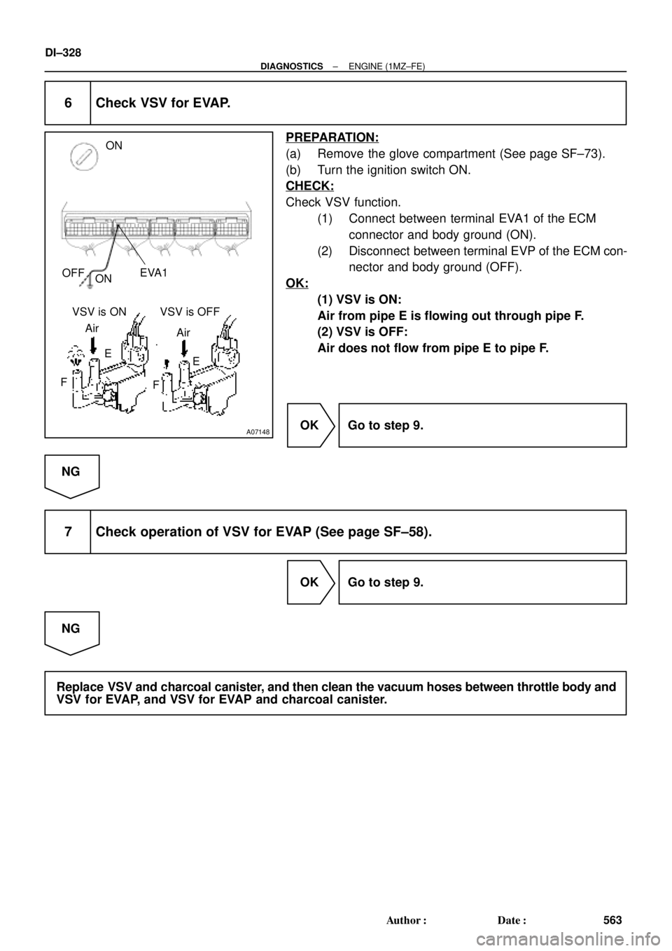
6 Check VSV for EVAP.
PREPARATION:
(a) Remove the glove compartment (See page SF±73).
(b) Turn the ignition switch ON.
CHECK:
Check VSV function.
(1) Connect between terminal EVA1 of the ECM
connector and body ground (ON).
(2) Disconnect between terminal EVP of the ECM con-
nector and body ground (OFF).
OK:
(1) VSV is ON:
Air from pipe E is flowing out through pipe F.
(2) VSV is OFF:
Air does not flow from pipe E to pipe F.
OK Go to step 9.
NG
7 Check operation of VSV for EVAP (See page SF±58).
OK Go to step 9.
NG
Replace VSV and charcoal canister, and then clean the vacuum hoses between throttle body and
VSV for EVAP, and VSV for EVAP and charcoal canister.
Page 1541 of 4592
A07149
ON
TPC
OFFON
VSV is ON
VSV is OFF
Air
E
FG Air
G E
F
± DIAGNOSTICSENGINE (1MZ±FE)
DI±329
564 Author�: Date�:
8 Check for open and short in harness and connector between EFI main relay
(Marking: EFI) and VSV for EVAP and ECM (See page IN±31).
NG Repair or replace harness or connector.
OK
Check and replace ECM (See page IN±31).
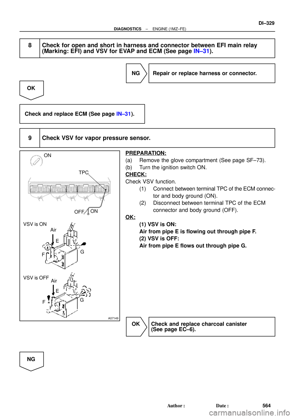
9 Check VSV for vapor pressure sensor.
PREPARATION:
(a) Remove the glove compartment (See page SF±73).
(b) Turn the ignition switch ON.
CHECK:
Check VSV function.
(1) Connect between terminal TPC of the ECM connec-
tor and body ground (ON).
(2) Disconnect between terminal TPC of the ECM
connector and body ground (OFF).
OK:
(1) VSV is ON:
Air from pipe E is flowing out through pipe F.
(2) VSV is OFF:
Air from pipe E flows out through pipe G.
OK Check and replace charcoal canister
(See page EC±6).
NG
Page 1547 of 4592
A02029
ON
SPD (+)
E8
± DIAGNOSTICSENGINE (1MZ±FE)
DI±335
570 Author�: Date�:
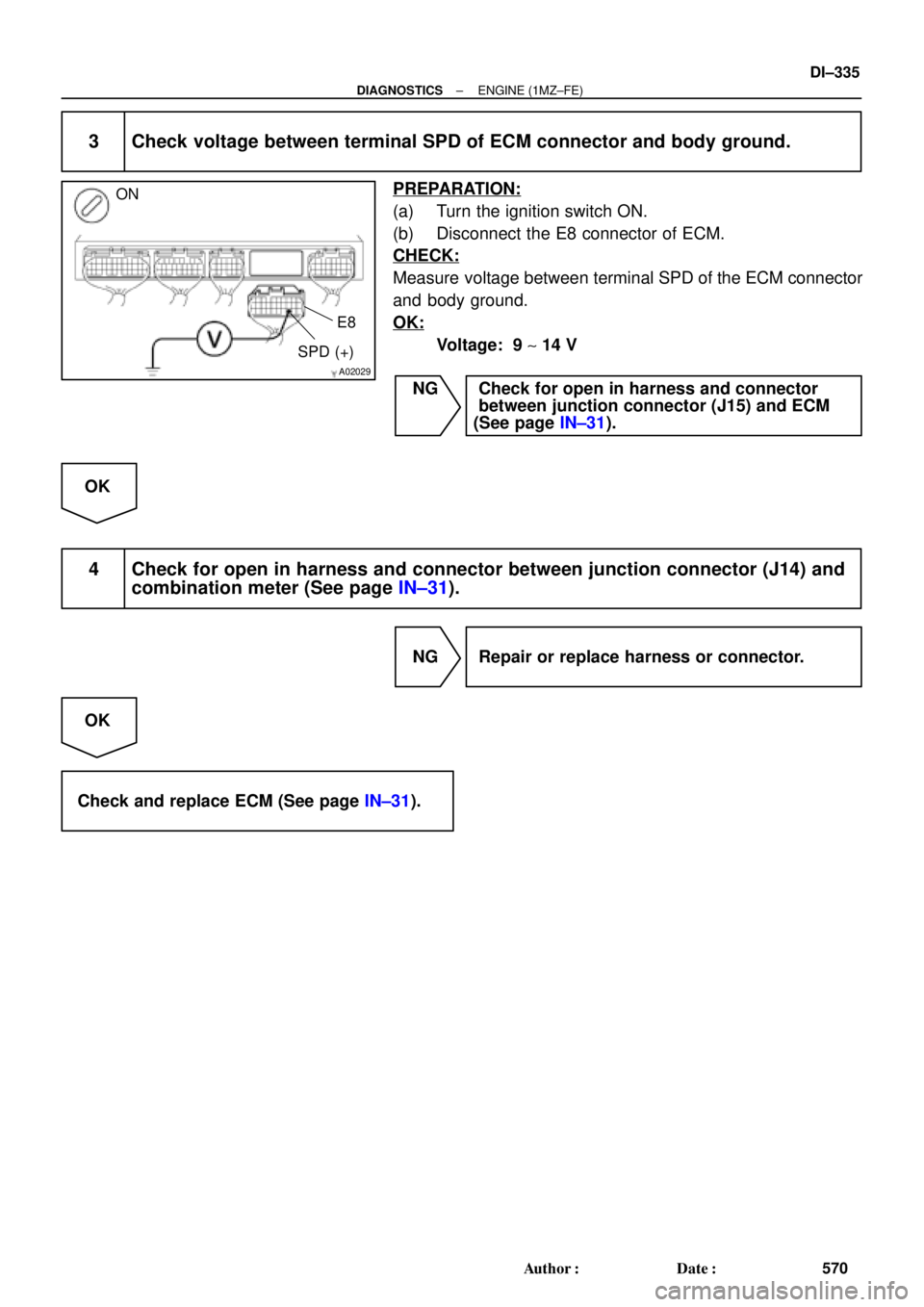
3 Check voltage between terminal SPD of ECM connector and body ground.
PREPARATION:
(a) Turn the ignition switch ON.
(b) Disconnect the E8 connector of ECM.
CHECK:
Measure voltage between terminal SPD of the ECM connector
and body ground.
OK:
Voltage: 9 ~ 14 V
NG Check for open in harness and connector
between junction connector (J15) and ECM
(See page IN±31).
OK
4 Check for open in harness and connector between junction connector (J14) and
combination meter (See page IN±31).
NG Repair or replace harness or connector.
OK
Check and replace ECM (See page IN±31).
Page 1550 of 4592
A02031
ON
RSO (+)E11
RSC (+)
DI±338
± DIAGNOSTICSENGINE (1MZ±FE)
573 Author�: Date�:
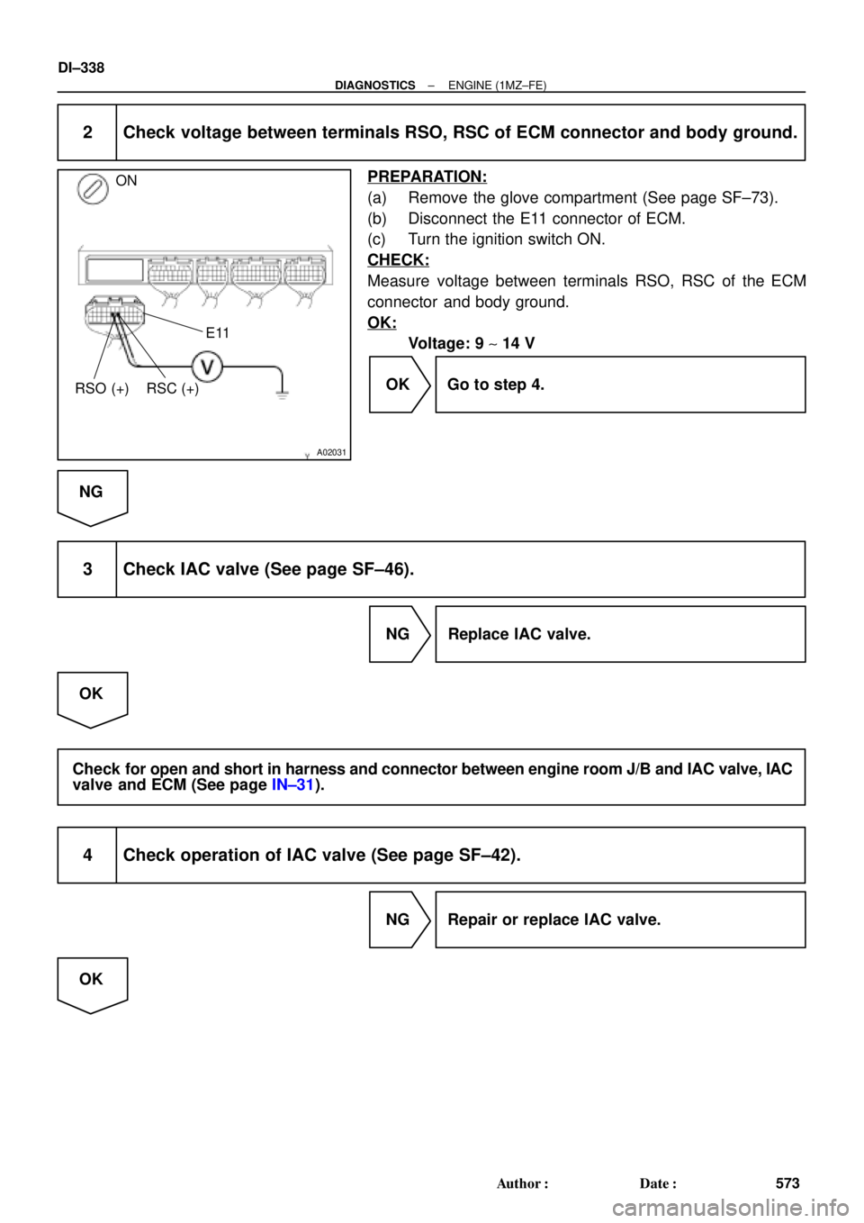
2 Check voltage between terminals RSO, RSC of ECM connector and body ground.
PREPARATION:
(a) Remove the glove compartment (See page SF±73).
(b) Disconnect the E11 connector of ECM.
(c) Turn the ignition switch ON.
CHECK:
Measure voltage between terminals RSO, RSC of the ECM
connector and body ground.
OK:
Voltage: 9 ~ 14 V
OK Go to step 4.
NG
3 Check IAC valve (See page SF±46).
NG Replace IAC valve.
OK
Check for open and short in harness and connector between engine room J/B and IAC valve, IAC
valve and ECM (See page IN±31).
4 Check operation of IAC valve (See page SF±42).
NG Repair or replace IAC valve.
OK
Page 1553 of 4592

Idling
IG SW OFF
3 ~ 5 min.
Time
(1) (2)(3)(4)
± DIAGNOSTICSENGINE (1MZ±FE)
DI±341
576 Author�: Date�:
CONFIRMATION DRIVING PATTERN
(a) Connect the")
A00364
Vehicle Speed
60 ~ 120 km/h
(38 ~ 75 mph)
Idling
IG SW OFF
3 ~ 5 min.
Time
(1) (2)(3)(4)
± DIAGNOSTICSENGINE (1MZ±FE)
DI±341
576 Author�: Date�:
CONFIRMATION DRIVING PATTERN
(a) Connect the TOYOTA hand±held tester to the DLC3.
(b) Switch the TOYOTA hand±held tester from normal mode to check mode (See page DI±197).
(c) Start the engine and warm it up with all accessory switches OFF.
(d) Drive the vehicle at 60 ~ 120 km/h (38 ~ 75 mph) and engine speed at 1,600 ~ 3,200 rpm for 3 ~ 5 min.
HINT:
If a malfunction exists, the MIL will light up during step (4).
NOTICE:
If the conditions in this test are not strictly followed, detection of the malfunction will not be possible.
If you do not have a TOYOTA hand±held tester, turn the ignition switch OFF after performing steps
(3) and (4), then perform steps (3) and (4) again.
INSPECTION PROCEDURE
HINT:
�If DTC P1130 is displayed, check Bank 1 Sensor 1 circuit.
�If DTC P1150 is displayed, check Bank 2 Sensor 1 circuit.
�Read frame freeze data using TOYOTA hand±held tester or OBD II scan tool. Because freeze frame
records the engine conditions when the malfunction is detected, when troubleshooting it is useful for
determining whether the vehicle was running or stopped, the engine warmed up or not, the air±fuel
ratio lean or rich, etc. at the time of the malfunction.
1 Are there any other codes (besides DTC P1130, P1150) being output?
YES Go to relevant DTC chart.
NO
Page 1561 of 4592

HAFR (+)
± DIAGNOSTICSENGINE (1MZ±FE)
DI±349
584 Author�: Date�:
DTC P1135 A/F Sensor Heater Circuit Malfunction
(Bank 1 Sensor 1) (Only for California Spec.)
DTC P1155 A/F Sensor")
A02509
HAFL (+)
HAFR (+)
± DIAGNOSTICSENGINE (1MZ±FE)
DI±349
584 Author�: Date�:
DTC P1135 A/F Sensor Heater Circuit Malfunction
(Bank 1 Sensor 1) (Only for California Spec.)
DTC P1155 A/F Sensor Heater Circuit Malfunction
(Bank 2 Sensor 1) (Only for California Spec.)
CIRCUIT DESCRIPTION
Refer to DTC P0125 (Insufficient Coolant Temp. for Closed Loop Fuel Control (Only for California Spec.))
on page DI±249.
DTC No.DTC Detecting ConditionTrouble Area
P1135
When heater operates, heater current exceeds 8 A
(2 trip detection logic)�Open or in heater circuit of A/F sensors
(bank 1, 2 sensor 1)P1135
P1155Heater current of 0.25 A or less when heater operates
(2 trip detection logic)
(bank 1, 2 sensor 1)
�A/F sensors (bank 1, 2 sensor 1) heater
�ECM
WIRING DIAGRAM
Refer to DTC P0125 (Insufficient Coolant Temp. for Closed Loop Fuel Control (Only for California Spec.))
on page DI±249.
INSPECTION PROCEDURE
HINT:
Read freeze frame data using TOYOTA hand±held tester or OBD II scan tool. Because freeze frame records
the engine conditions when the malfunction is detected, when troubleshooting it is useful for determining
whether the vehicle was running or stopped, the engine warmed up or not, the air±fuel ratio lean or rich, etc.
at the time of the malfunction.
1 Check voltage between terminal HAFR, HAFL of ECM connector and body
ground.
PREPARATION:
(a) Remove glove compartment (See page SF±73).
(b) Turn the ignition switch ON.
CHECK:
Measure voltage between terminals HAFR, HAFL of the ECM
connector and body ground.
OK:
Voltage: 9 ~ 14 V
OK Check and replace ECM (See page IN±31).
NG
DI1K8±04
Page 1563 of 4592

S00251
From BatteryIgnition Coil
Spark Plug
IGC1
IGC2
IGC3
GND TA C IGT1
IGT2
IGT3
IGF
To Tachometer ECM G
NE
Camshaft
Position
Sensor
Crankshaft
Position
Sensor
Various
SensorNo.2 Cylinder
No.1 Cylinder
No.4 Cylinder
No.3 Cylinder
No.6 Cylinder
No.5 Cylinder
± DIAGNOSTICSENGINE (1MZ±FE)
DI±351
586 Author�: Date�:
DTC P1300 Igniter Circuit Malfunction
CIRCUIT DESCRIPTION
A DIS (Direct Ignition System) has been adopted. The DIS improves the ignition timing accuracy, reduces
high±voltage loss, and enhances the overall reliability of the ignition system by eliminating the distributor.
The DIS is a 2±cylinder simultaneous ignition system which ignites 2 cylinders simultaneously with one igni-
tion coil. In the 2±cylinder simultaneous ignition system, each of the 2 spark plugs is connected to the end
of the secondary winding. High voltage generated in the secondary winding is applied directly to the spark
plugs. The sparks of the 2 spark plugs pass simultaneously from the center electrode to the ground elec-
trode.
The ECM determines ignition timing and outputs the ignition signals (IGT) for each cylinder. Based on IGT
signals, the igniter controls the primary ignition signals (IGC) for all ignition coils. At the same time, the igniter
also sends an ignition confirmation signal (IGF) as a fail±safe measure to the ECM.
DTC No.DTC Detecting ConditionTrouble Area
P1300
Condition (a) is repeated 3 times consecutively during 6
consecutively IGT signals while engine is running
(a) IGF signal is not input to ECM for 2 or more ignitions�Open or short in IGF or IGT circuit from igniter to ECM
�Igniter
�ECM
DI084±06