Page 1564 of 4592
S05723
J18
Junction
Connector
A
A A A AII3B±R
B±R B±R W±R128 3
1K 1C
Ignition
Switch
76
1K
1BB±R
G
B±R
B±R Y
LIgnition Coil
Spark Plug
No.1
No.2
No.3
11
12
2
2
ED
BR
3 2 1
10
9
7
6
5
4
W±R LG±B
BR±Y
IgniterECM
IGT1
IGT2
IGT3
IGF5 VInstrument
Panel J/B
E1125
E1113
E1112
E1111GR
B±R
5
5
W±R
Engine Room J/B
2L4
AM2
2A1
B
Fusible
Link
Block 1
1
F6
B±GFL
MAIN
Battery
F4
Instrument
Panel J/B
DI±352
± DIAGNOSTICSENGINE (1MZ±FE)
587 Author�: Date�:
WIRING DIAGRAM
INSPECTION PROCEDURE
HINT:
Read freeze frame data using TOYOTA hand±held tester or OBD II scan tool. Because freeze frame records
the engine conditions when the malfunction is detected, when troubleshooting it is useful for determining
whether the vehicle was running or stopped, the engine warmed up or not, the air±fuel ratio lean or rich, etc.
at the time of the malfunction.
1 Check spark plug and spark of misfiring cylinder (See page DI±276).
NG Go to step 4.
OK
Page 1565 of 4592
A02033
ON
IGF (+)
± DIAGNOSTICSENGINE (1MZ±FE)
DI±353
588 Author�: Date�:
2 Check for open and short in harness and connector in IGF signal circuit between
ECM and igniter (See page IN±31).
NG Repair or replace harness or connector.
OK
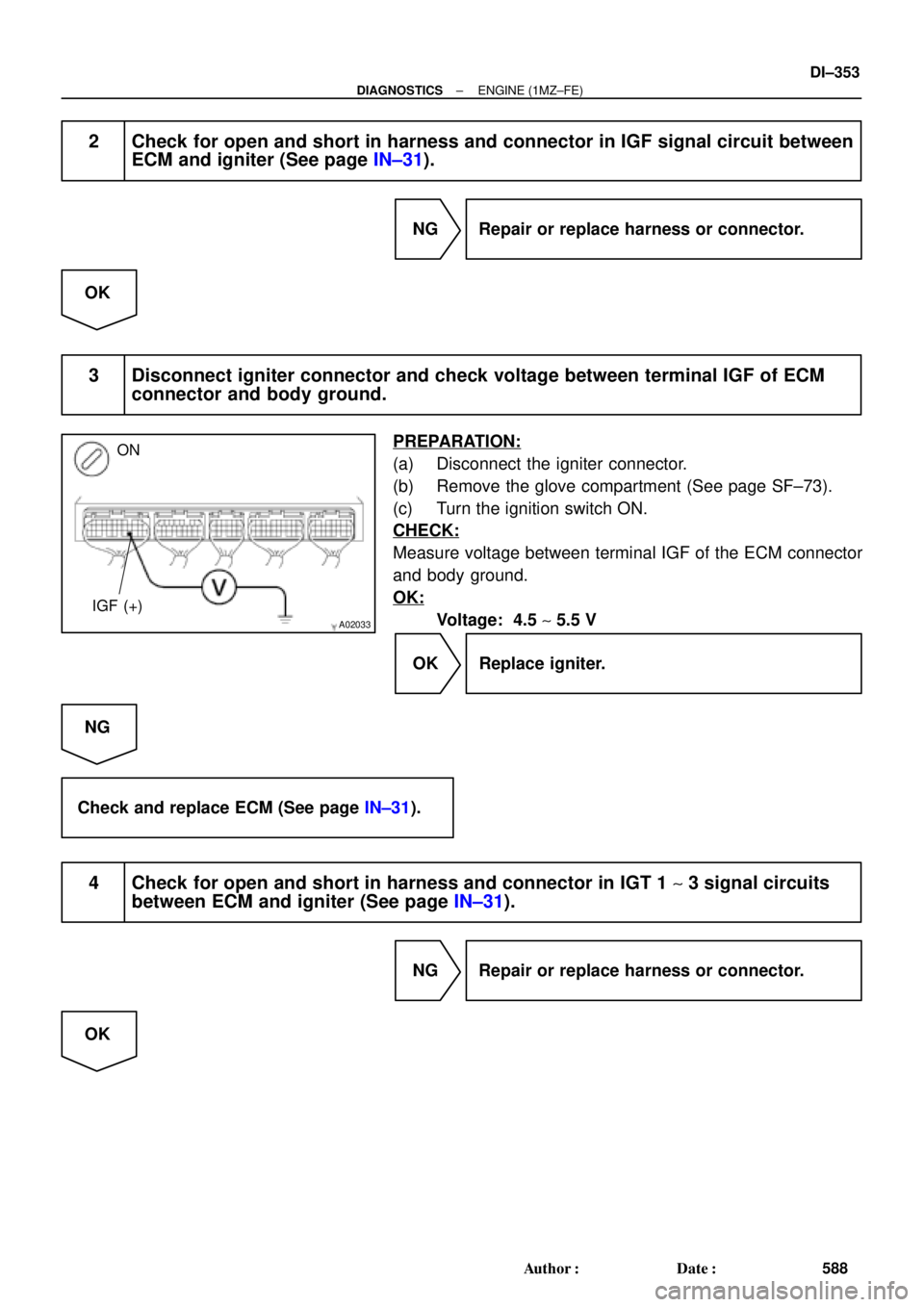
3 Disconnect igniter connector and check voltage between terminal IGF of ECM
connector and body ground.
PREPARATION:
(a) Disconnect the igniter connector.
(b) Remove the glove compartment (See page SF±73).
(c) Turn the ignition switch ON.
CHECK:
Measure voltage between terminal IGF of the ECM connector
and body ground.
OK:
Voltage: 4.5 ~ 5.5 V
OK Replace igniter.
NG
Check and replace ECM (See page IN±31).
4 Check for open and short in harness and connector in IGT 1 ~ 3 signal circuits
between ECM and igniter (See page IN±31).
NG Repair or replace harness or connector.
OK
Page 1567 of 4592
BE6653
P24329A00124
ON START
9 (+)
± DIAGNOSTICSENGINE (1MZ±FE)
DI±355
590 Author�: Date�:
7 Check voltage between terminal 9 of igniter connector and body ground.
PREPARATION:
Disconnect the igniter connector.
CHECK:
Measure voltage between terminal 9 of igniter connector and
body ground when ignition switch is turned to ºONº and
ºSTARTº position.
OK:
Voltage: 9 ~ 14 V
NG Check and repair igniter power source circuit
(See page IG±1).
OK
8 Check for open and short in harness and connector between ignition switch and
ignition coil, and ignition coil and igniter (See page IN±31).
NG Repair or replace harness or connector.
OK
9 Check ignition coil (See page IG±1).
NG Replace ignition coil.
OK
Page 1571 of 4592

BE6653S05694
S05742
1
2
± DIAGNOSTICSENGINE (1MZ±FE)
DI±359
594 Author�: Date�:
INSPECTION PROCEDURE
HINT:
�If DTCs ºP0110º (Intake Air Temp. Circuit Malfunction), ºP0115º (Engi")
A00379
ON
1 (+)
BE6653S05694
S05742
1
2
± DIAGNOSTICSENGINE (1MZ±FE)
DI±359
594 Author�: Date�:
INSPECTION PROCEDURE
HINT:
�If DTCs ºP0110º (Intake Air Temp. Circuit Malfunction), ºP0115º (Engine Coolant Temp. Circuit Mal-
function), ºP0120º (Throttle/Pedal Position/Switch ºAº Circuit Malfunction), ºP1410º (EGR Valve Posi-
tion Sensor Circuit Malfunction) are output simultaneously, E2 (Sensor Ground) may be open.
�Read freeze frame data using TOYOTA hand±held tester or OBD II scan tool. Because freeze frame
records the engine conditions when the malfunction is detected, when troubleshooting it is useful for
determining whether the vehicle was running or stopped, the engine warmed up or not, the air±fuel
ratio lean or rich, etc. at the time of the malfunction.
1 Check voltage between terminal VC of wire harness side connector and body
ground.
PREPARATION:
(a) Disconnect the vacuum hose from EGR valve.
(b) Disconnect the EGR valve position sensor connector.
(c) Turn the ignition switch ON.
CHECK:
Measure voltage between terminal 1 of wire harness side con-
nector and body ground.
OK:
Voltage: 4.5 ~ 5.5 V
NG Go to step 4.
OK
2 Check EGR valve position sensor.
PREPARATION:
Disconnect the EGR valve position sensor connector.
CHECK:
Measure resistance between terminals 1 (VC) and 2 (E2) of
EGR valve position sensor.
OK:
Resistance: 1.5 ~ 4.3 kW
NG Replace EGR valve position sensor.
OK
Page 1572 of 4592
A02036
ON
EGLS (+) E2 (±)
DI±360
± DIAGNOSTICSENGINE (1MZ±FE)
595 Author�: Date�:
3 Check voltage between terminals EGLS and E2 of ECM connectors.
PREPARATION:
(a) Disconnect the vacuum hose from EGR valve.
(b) Connect the hand±held vacuum pump to EGR valve.
(c) Remove the glove compartment (See page SF±73).
(d) Turn the ignition switch ON.
CHECK:
Measure voltage between terminals EGLS and E2 of the ECM
connectors.
OK:
ConditionVltEGR valveVacuumVoltage
Fully closed0 kPa
(0 mmHg, 0 in.Hg)0.4 ~ 1.6 V
Fully open17.3 kPa
(130 mmHg, 5.12 in.Hg)3.2 ~ 5.1 V
NG Check for open and short in harness and
connector between ECM and EGR valve
position sensor (EGLS or E2 line).
OK
Check and replace ECM (See page IN±31).
Page 1573 of 4592
A02022
ON
VC (+) E2 (±)
± DIAGNOSTICSENGINE (1MZ±FE)
DI±361
596 Author�: Date�:
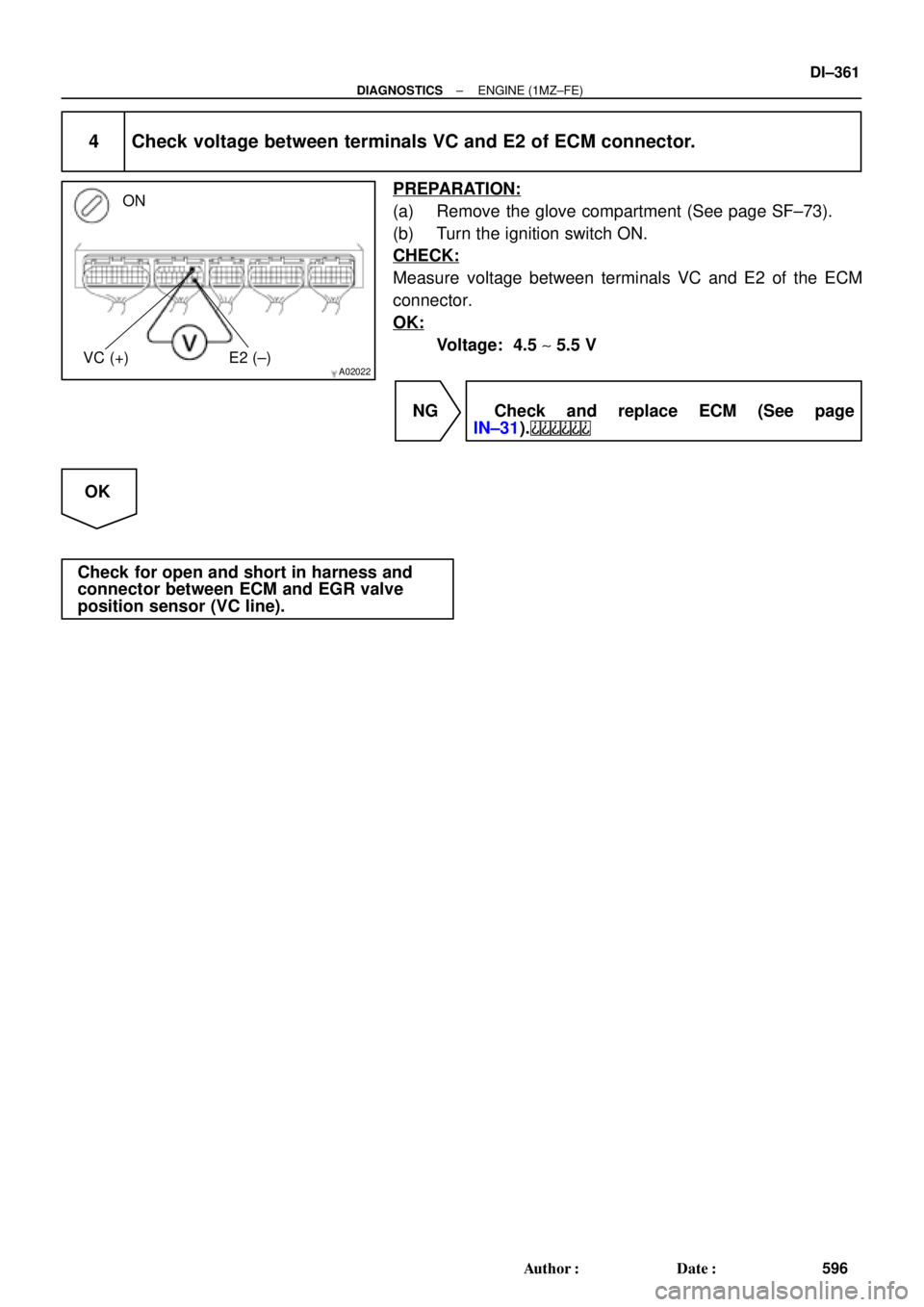
4 Check voltage between terminals VC and E2 of ECM connector.
PREPARATION:
(a) Remove the glove compartment (See page SF±73).
(b) Turn the ignition switch ON.
CHECK:
Measure voltage between terminals VC and E2 of the ECM
connector.
OK:
Voltage: 4.5 ~ 5.5 V
NG Check and replace ECM (See page
IN±31).
OK
Check for open and short in harness and
connector between ECM and EGR valve
position sensor (VC line).
Page 1576 of 4592

DI±364
± DIAGNOSTICSENGINE (1MZ±FE)
599 Author�: Date�:
INSPECTION PROCEDURE
HINT:
Read freeze frame data using TOYOTA hand±held test")
A02037
ON
ON
Brake Pedal
DepressedBrake Pedal
Released
STP (+)
DI±364
± DIAGNOSTICSENGINE (1MZ±FE)
599 Author�: Date�:
INSPECTION PROCEDURE
HINT:
Read freeze frame data using TOYOTA hand±held tester or OBD II scan tool. Because freeze frame records
the engine conditions when the malfunction is detected, when troubleshooting it is useful for determining
whether the vehicle was running or stopped, the engine warmed up or not, the air±fuel ratio lean or rich, etc.
at the time of the malfunction.
1 Check operation of stop light.
CHECK:
Check if the stop lights go on and off normally when the brake pedal is operated and released.
NG Check and repair stop light circuit.
OK
2 Check STP signal.
When using TOYOTA hand±held tester:
PREPARATION:
(a) Connect the TOYOTA hand±held tester to the DLC3.
(b) Turn the ignition switch ON and push the TOYOTA hand±
held tester main switch ON.
CHECK:
Read the STP signal on the TOYOTA hand±held tester.
OK:
Brake pedal is depressed: STP ...... ON
Brake pedal is released: STP ...... OFF
When not using TOYOTA hand±held tester:
PREPARATION:
Turn the ignition switch ON.
CHECK:
Check voltage between terminal STP of the ECM connector
and body ground.
OK:
Brake pedalVoltage
Depressed7.5 ~ 14 V
ReleasedBelow 1.5 V
OK Check for intermittent problems
(See page DI±197).
NG
Page 1578 of 4592

601 Author�: Date�:
DTC P1600 ECM BATT Malfunction
CIRC")
S05470
Battery FL
MAIN B±G
F4
F61 1
18
B Fusible
Link
BlockEngine Room J/B No.2
2A2JB±YECM
BATT EFI
E71 DI±366
± DIAGNOSTICSENGINE (1MZ±FE)
601 Author�: Date�:
DTC P1600 ECM BATT Malfunction
CIRCUIT DESCRIPTION
Battery positive voltage is supplied to terminal BATT of the ECM even when the ignition switch is OFF for
use by the DTC memory and air±fuel ratio adaptive control value memory, etc.
DTC No.DTC Detecting ConditionTrouble Area
P1600Open in back up power source circuit�Open in back up power source circuit
�ECM
HINT:
If DTC P1600 appear, the ECM does not store another DTC.
WIRING DIAGRAM
INSPECTION PROCEDURE
HINT:
Read freeze frame data using TOYOTA hand±held tester or OBD II scan tool. Because free frame records
the engine conditions when the malfunction is detected, when troubleshooting it is useful for determining
whether the vehicle was running or stopped, the engine warmed up or not, the air±fuel ratio lean or rich, etc.
at the time of the malfunction.
DI089±06