Page 1621 of 4592
 w/ Engine Immobiliser System
w/o Engine Immobiliser System(+)
(±)
(+)
AT7809
4.5 ~ 5.5 V
0
Turn the wheel
± DIAGNOSTICSAUTOMATIC TRANSAXLE (A140E)
DI±409
644 Author�: D")
A03021D02238
SPD
SPD
ON
(±) w/ Engine Immobiliser System
w/o Engine Immobiliser System(+)
(±)
(+)
AT7809
4.5 ~ 5.5 V
0
Turn the wheel
± DIAGNOSTICSAUTOMATIC TRANSAXLE (A140E)
DI±409
644 Author�: Date�:
INSPECTION PROCEDURE
1 Check operation of speedometer.
CHECK:
Drive the vehicle and check if the operation of the speedmeter in the combination meter is normal.
HINT:
The vehicle speed sensor is operating normally if the speedometer display is normal.
NG Check speedometer circuit. See combination
meter troubleshooting (See page BE±47).
OK
2 Check voltage between terminal SPD of ECM connector and body ground.
PREPARATION:
(a) Remove glove compartment (See page BO±75).
(b) Shift the shift lever to neutral.
(c) Jack up one of the front wheels.
(d) Turn ignition switch ON.
CHECK:
Measure voltage between terminal SPD of ECM connector and
body ground when the wheel is turned slowly.
OK:
Voltage is generated intermittently.
NG Check and repair harness and connector
between combination meter and ECM
(See page IN±31).
OK
Page 1637 of 4592

D01820
Combination
Meter
R
C8R ± B
13
IG13
2
L8
11
6 C8
C8O
Y16
IG13
*3 L ± W
*4 O
1HInstrument
Panel J/BECM
1V Park/Neutral
Position Switch
P1
L ± W
B ± WII2
E
8 34
P1
P1 P12Y
R ± BII2
J29
Junction
Connector E
E
Y10
5
Y19
15
*1
*2
E7
E7
E7
E7
E7
E7R2 L
1816
*1
*2
17
22B
+
NSW *3 L ± W
*4 O
R ± B
R ± B
B ± W
DD
D
J29
Junction
Connector
J27J27
J28 CC
A
R ± B
B ± W 5
6
3
11II3
II2
B
BB R ± L A
A
J21
Junction
Connector
J28
Junction
Connector
5 2II2R ± L
F
F6
B ± R
F9
ALT
B ± G
B ± R
1
112F9
F4F6
FL
MAIN
BatteryAM1
1B
2L12
55 1B
1K1K
2A 41
AM2 W ± R
B GR
II2
W ± R
10*5
*6GR
B ± O
C
J8B*5
*6GR
B ± O
BW2
74
8 I16 I16
I16 I16Ignition Switch
B ± Y
R11
43 1K
1K1J
1J GAUGE
STARTER
MAINST Relay
2BB ± W
3
115
9
2J2D
2K 5
3
12 Y
J29
Junction
Connector
J27, J28
Junction Connector
*3 L ± W
*4 O
Instrument Panel J/B
Instrument Panel J/B Instrument Panel J/B
Engine Room J/B No.2
J11 Junction Connector
*1: w/ Engine Immobiliser System
*2: w/o Engine Immobiliser System
*3: TMC Made*4: TMMK Made
*5: TMC Made w/o Traction Control
*6: Except TMC Made w/o Traction ControlInstrument Panel J/B
Starter
J7A
IK R ± L
J7 J8 Junction Connector Engine Room J/B No.2 R ± L
± DIAGNOSTICSAUTOMATIC TRANSAXLE (A140E)
DI±425
660 Author�: Date�:
WIRING DIAGRAM
Page 1638 of 4592
(+) (+)
(±)
Position
P, N
R
D
2
LNSW±Body
groundR±Body
ground2±Body
groundL±Body
grou")
D00043 Q08479BE3840D00994
w/ Engine Immobiliser System
w/o Engine Immobiliser SystemON
NSW
LL
2
R
NSWR
2
(±)(+) (+)
(±)
Position
P, N
R
D
2
LNSW±Body
groundR±Body
ground2±Body
groundL±Body
ground
0 V
0 V0 V0 V
0 V
0 V
0 V 0 V
0 V
0 V 0 V
0 V
0 V 9 ~ 14 V*
9 ~ 14 V
9 ~ 14 V
9 ~ 14 V9 ~ 14 V
9 ~ 14 V 9 ~ 14 V*
DI±426
± DIAGNOSTICSAUTOMATIC TRANSAXLE (A140E)
661 Author�: Date�:
INSPECTION PROCEDURE
1 Read PNP, REVERSE, 2ND and LOW signals.
When using TOYOTA hand±held tester:
PREPARATION:
(a) Remove the DLC3 cover.
(b) Connect a TOYOTA hand±held tester to the DLC3.
(c) Turn the ignition switch ON and TOYOTA hand±held tes-
ter main switch ON.
CHECK:
Shift the shift lever into the P, R, N, 2 and L positions, and read
the PNP, REVERSE, 2ND and LOW signals on the TOYOTA
hand±held tester.
OK:
Shift positionSignal
22ND OFF " ON
LLOW OFF " ON
RREVERSE OFF " ON
P, NPNP OFF " ON
When not using TOYOTA hand±held tester:
PREPARATION:
Turn the ignition switch ON.
CHECK:
Measure voltage between terminals NSW, 2, L and R of ECM
and body ground when the shift lever is shifted in the following
positions.
OK:
HINT:
The voltage will drop slightly due to lighting up of the back up
light.
OK Proceed to next circuit inspection shown on
matrix chart (See page DI±405).
NG
Page 1641 of 4592
Q07658
D00103BE3840D00995
w/ Engine Immobiliser System
w/o Engine Immobiliser SystemON
OD1
OD1 (+)
(±)
BE3840
I00143D00057
ON
OD (+) (±)
± DIAGNOSTICSAUTOMATIC TRANSAXLE (A140E)
DI±429
664 Author�: Date�:
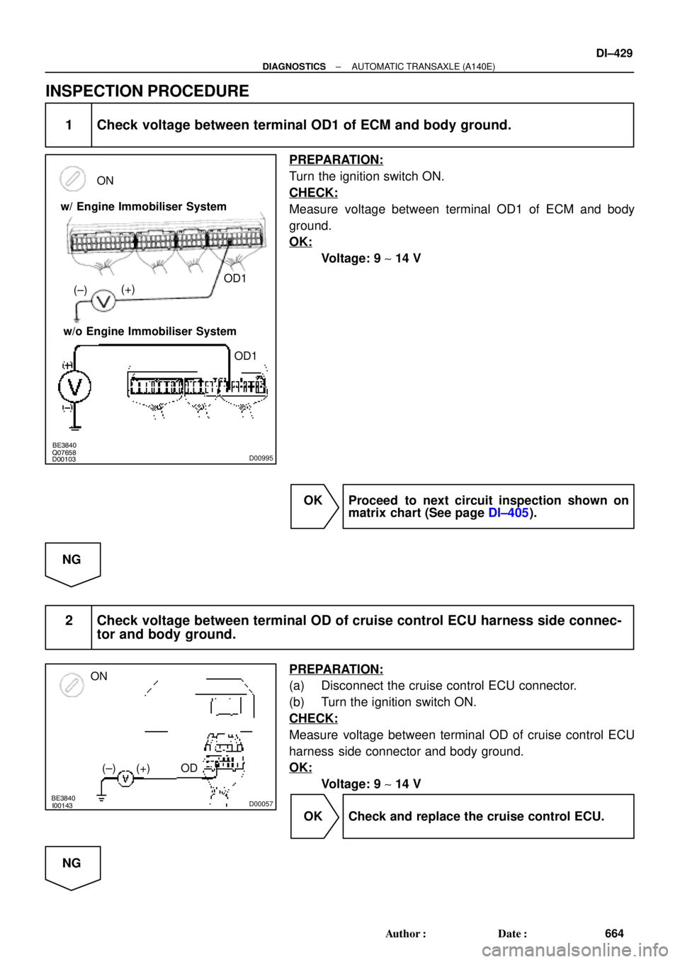
INSPECTION PROCEDURE
1 Check voltage between terminal OD1 of ECM and body ground.
PREPARATION:
Turn the ignition switch ON.
CHECK:
Measure voltage between terminal OD1 of ECM and body
ground.
OK:
Voltage: 9 ~ 14 V
OK Proceed to next circuit inspection shown on
matrix chart (See page DI±405).
NG
2 Check voltage between terminal OD of cruise control ECU harness side connec-
tor and body ground.
PREPARATION:
(a) Disconnect the cruise control ECU connector.
(b) Turn the ignition switch ON.
CHECK:
Measure voltage between terminal OD of cruise control ECU
harness side connector and body ground.
OK:
Voltage: 9 ~ 14 V
OK Check and replace the cruise control ECU.
NG
Page 1643 of 4592

D01810
: w/ Engine Immobiliser System
: w/o Engine Immobiliser System
: O/D Main Switch
Contacts go open with switch pushed in
Contacts go closed with switch pushed once againInstrument
Panel J/BIgnition Switch
1B1
AM1
W
I16
7 1
22
1K2
AM1 IG1
B ± Y
O/D OFF
Indicator Light
(Combination Meter) R ± L
R ± LGAUGE
J4
Junction
Connector
DI164
2
1D 1K
D12
C8G ± OC
C8
W ± B C
CG ± O
G ± OJ6
Junction
ConnectorECM
5
*1B+
E77*2
E7OD2G ± O
IG311
O2 2
(*3)
O/D Main
Switch
O2
4
W ± B A
IF AJ5
Junction
Connector B ± R
1
FUSIBLE
LINK
BLOCKALT F9B ± R
2
F9
1
F4B ± GFL
MAIN
Battery
*3 *2 *1
1 Instrument
Panel J/B
± DIAGNOSTICSAUTOMATIC TRANSAXLE (A140E)
DI±431
666 Author�: Date�:
O/D Main Switch & O/D OFF Indictor Light Circuit
CIRCUIT DESCRIPTION
The O/D main switch contacts go open when the switch is pushed in and go closed when it is pushed out.
In O/D main switch in OFF position, the O/D OFF indicator light lights up, and the ECM prohibits shifting over-
drive.
WIRING DIAGRAM
DI1J1±01
Page 1645 of 4592
Q07754Q07661BE3840D01716
ON
(+)
OD2
(±) w/ Engine Immobiliser System
w/o Engine Immobiliser System
OD2
± DIAGNOSTICSAUTOMATIC TRANSAXLE (A140E)
DI±433
668 Author�: Date�:
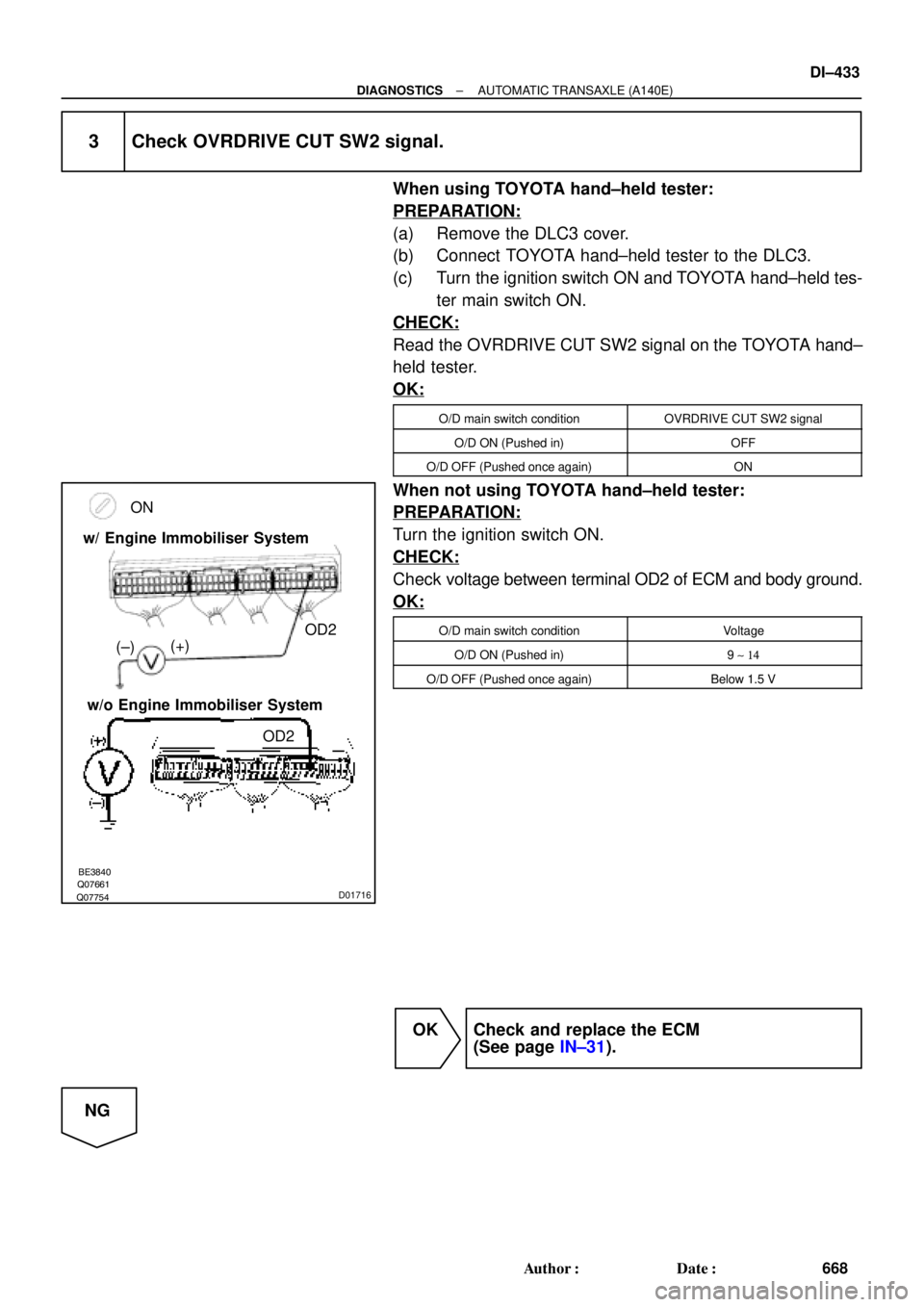
3 Check OVRDRIVE CUT SW2 signal.
When using TOYOTA hand±held tester:
PREPARATION:
(a) Remove the DLC3 cover.
(b) Connect TOYOTA hand±held tester to the DLC3.
(c) Turn the ignition switch ON and TOYOTA hand±held tes-
ter main switch ON.
CHECK:
Read the OVRDRIVE CUT SW2 signal on the TOYOTA hand±
held tester.
OK:
O/D main switch conditionOVRDRIVE CUT SW2 signal
O/D ON (Pushed in)OFF
O/D OFF (Pushed once again)ON
When not using TOYOTA hand±held tester:
PREPARATION:
Turn the ignition switch ON.
CHECK:
Check voltage between terminal OD2 of ECM and body ground.
OK:
O/D main switch conditionVoltage
O/D ON (Pushed in)9 ~ 14
O/D OFF (Pushed once again)Below 1.5 V
OK Check and replace the ECM
(See page IN±31).
NG
Page 1651 of 4592

DI±439
674 Author�: Date�: �
The diagnosis system operates in normal mode
during normal vehicle use, and also has a check
mode for technicians to simu")
N09214
± DIAGNOSTICSAUTOMATIC TRANSAXLE (A541E)
DI±439
674 Author�: Date�: �
The diagnosis system operates in normal mode
during normal vehicle use, and also has a check
mode for technicians to simulate malfunction symp-
toms and perform troubleshooting. Most DTCs use
2 trip detection logic(*) to prevent erroneous detec-
tion. By switching the ECM to check mode when
troubleshooting, the technician can cause the MIL
to light up and for a malfunction that is only detected
once or momentarily.
(TOYOTA hand±held tester) (See page DI±438)
�*2 trip detection logic:
When a logic malfunction is first detected, the mal-
function is temporarily stored in the ECM memory.
If the same malfunction is detected again during the
2nd test drive, this 2nd detection causes the MIL to
light up.
(b) Inspect the DLC3.
The vehicle's ECM uses ISO 9141±2 for communication.
The terminal arrangement of DLC3 complies with SAE
J1962 and matches the ISO 9141±2 format.
Tester connectionConditionSpecified condition
7 (Bus � Line) ± 5 (Signal ground)During communicationPulse generation
4 (Chassis Ground) ± BodyAlways1 W or less
5 (Signal Ground) ± BodyAlways1 W or less
16 (B+) ± BodyAlways9 ± 14 V
HINT:
If your display shows ºUNABLE TO CONNECT TO VEHICLEº
when you have connected the cable of OBD II scan tool or TOY-
OTA hand±held tester to DLC3, turned the ignition switch ON
and operated the scan tool, there is a problem on the vehicle
side or tool side.
(1) If communication is normal when the tool is con-
nected to another vehicle, inspect DLC3 on the orig-
inal vehicle.
(2) If communication is still not possible when the tool
is connected connected to another vehicle, the
problem is probably in the tool itself, so consult the
Service Department listed in the tool's instruction
manual.
Page 1652 of 4592

675 Author�: Date�:
2. INSPECT DIAGNOSIS (NORMAL MODE)
(a) Check the MIL.
(1) The MIL comes on when the ig")
FI0534
S05335
TOYOTA hand±held tester
DLC3
DI±440
± DIAGNOSTICSAUTOMATIC TRANSAXLE (A541E)
675 Author�: Date�:
2. INSPECT DIAGNOSIS (NORMAL MODE)
(a) Check the MIL.
(1) The MIL comes on when the ignition switch is turned
ON and the engine is not running.
HINT:
If the MIL does not light up, troubleshoot the combination meter
(See page BE±2).
(2) When the engine is started, the MIL should go off.
If the lamp remains on, the diagnosis system has
detected a malfunction or abnormality in the sys-
tem.
(b) Check the DTC.
NOTICE:
TOYOTA hand±held tester only:
When the diagnostic system is switched from normal mode
to check mode, it erases all DTCs and freeze frame data re-
corded in normal mode. So before switching modes, al-
ways check the DTCs and freeze frame data, and note them
down.
(1) Prepare an OBD II scan tool (complying with SAE
J1978) or TOYOTA hand±held tester.
(2) Connect the OBD II scan tool or TOYOTA hand±
held tester to DLC3 at the lower of the instrument
panel.
(3) Turn the ignition switch ON and turn the OBD II scan
tool or TOYOTA hand±held tester switch ON.
(4) Use the OBD II scan tool or TOYOTA hand±held
tester to check the DTCs and freeze frame data and
note them down (For operating instructions, see the
OBD II scan tool's instruction book).
(5) See page DI±449 to confirm the details of the DTCs.
NOTICE:
When simulating symptoms with an OBD II scan tool (ex-
cluding TOYOTA hand±held tester) to check the DTCs, use
normal mode. For codes on the DTCs chart subject to º2
trip detection logicº, turn the ignition switch off after the
symptoms have been simulated the 1st time. Them repeat
the simulation process again. When the program has DTCs
are recorded in the ECM.