Page 1700 of 4592
Q07595
2
4
DI±488
± DIAGNOSTICSAUTOMATIC TRANSAXLE (A541E)
723 Author�: Date�:
INSPECTION PROCEDURE
O/D OFF indicator light does not light up
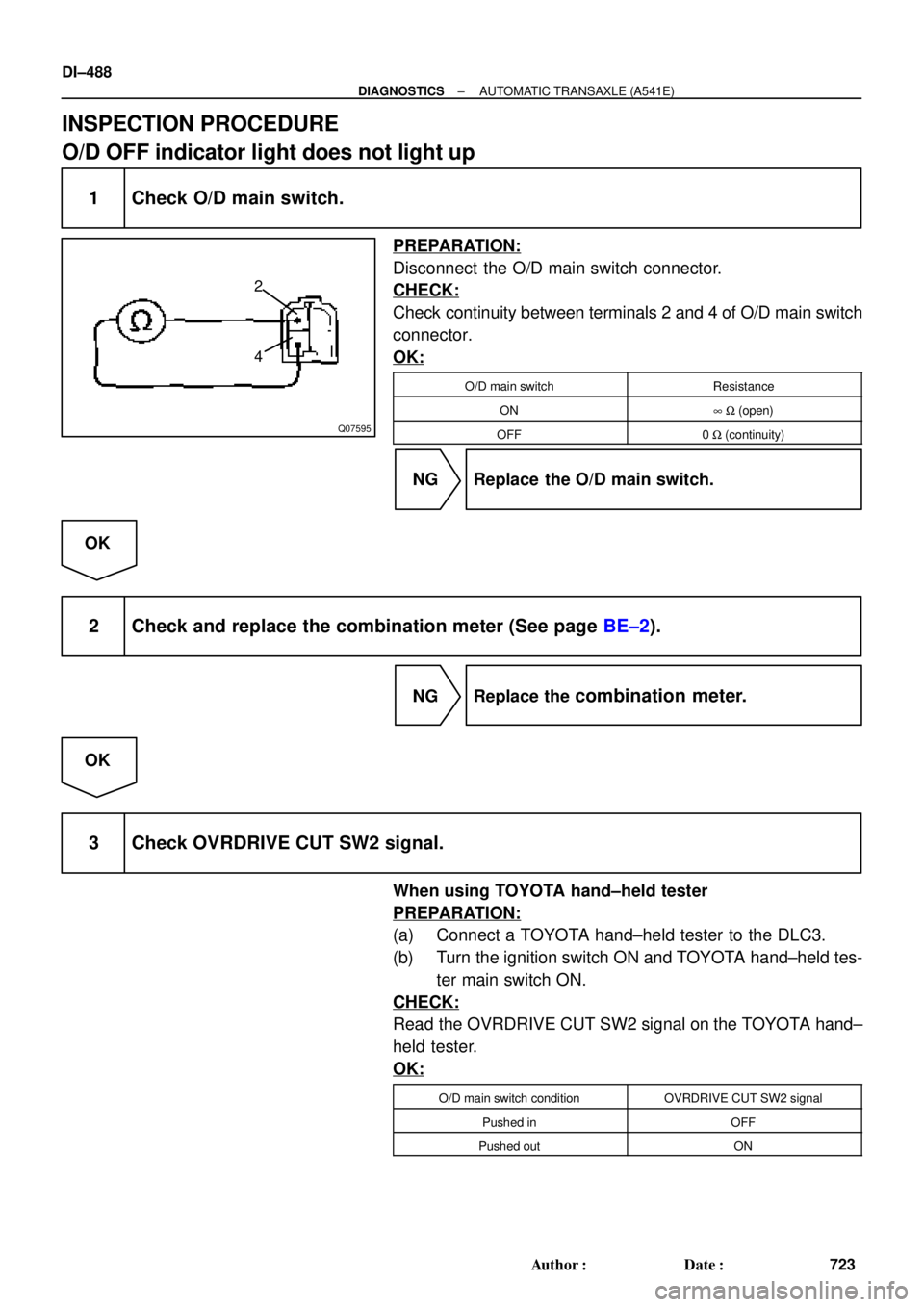
1 Check O/D main switch.
PREPARATION:
Disconnect the O/D main switch connector.
CHECK:
Check continuity between terminals 2 and 4 of O/D main switch
connector.
OK:
O/D main switchResistance
ON8 W (open)
OFF0 W (continuity)
NG Replace the O/D main switch.
OK
2 Check and replace the combination meter (See page BE±2).
NG Replace the combination meter.
OK
3 Check OVRDRIVE CUT SW2 signal.
When using TOYOTA hand±held tester
PREPARATION:
(a) Connect a TOYOTA hand±held tester to the DLC3.
(b) Turn the ignition switch ON and TOYOTA hand±held tes-
ter main switch ON.
CHECK:
Read the OVRDRIVE CUT SW2 signal on the TOYOTA hand±
held tester.
OK:
O/D main switch conditionOVRDRIVE CUT SW2 signal
Pushed inOFF
Pushed outON
Page 1701 of 4592
BE3840
D00837Q07662D01916
Except California, w/ Engine Immobilizer
and / or TRAC:
California, w/ Engine Immobilizer
and / or TRAC:
OD2 OD2
(+) (±) ON
(+) (±)
± DIAGNOSTICSAUTOMATIC TRANSAXLE (A541E)
DI±489
724 Author�: Date�:
When not using TOYOTA hand±held tester
PREPARATION:
Turn the ignition switch ON.
CHECK:
Check voltage between terminal OD2 of ECM and body ground.
OK:
O/D main switchVoltage
OFFBelow 1 V
ON10 ~ 14 V
NG Check and replace the ECM.
NG
4 Check harness and connector between O/D OFF indicator light and ECM
(See page IN±31).
NG Repair or replace the harness or connector.
OK
Check and replace the ECM.
Page 1705 of 4592

DI03C±03
F00047
F00006
DLC1Short Pin
S-17-1 Iei-23-1-A
F00041
DLC2 DLC1
Tc E1
E1Tc
R01346
Normal Code
0.25 sec.
0.25 sec. 2 sec.
ON
OFF
ON
OFF0.5 sec. 0.5 sec.
Code 11 and 21
4 sec.1.5 sec.
2.5 sec.
Code 11 Code 21
± DIAGNOSTICSANTI±LOCK BRAKE SYSTEM (DENSO Made)
DI±493
728 Author�: Date�:
PRE±CHECK
1. DIAGNOSIS SYSTEM
(a) Check the indicator.
When the ignition switch is turned ON, check that the ABS
warning light goes on for 3 seconds.
HINT:
If the indicator check result is not normal, proceed to
troubleshooting for the ABS warning light circuit
(See page DI±529).
(b) Check the DTC.
(1) Disconnect the short pin from DLC1.
(2) Using SST, connect terminals Tc and E
1 of DLC2 or
DLC1.
SST 09843 ± 18020
(3) Turn the ignition switch ON.
(4) Read the DTC from the ABS warning light on the
combination meter.
HINT:
�If no code appears, inspect the diagnostic circuit or ABS
warning light circuit (See page DI±532 or DI±529).
�As an example, the blinking patterns for normal code and
codes 11 and 21 are shown on the left.
(5) Codes are explained in the code table on page
DI±497.
(6) After completing the check, disconnect terminals Tc
and E
1, and turn off the display.
If 2 or more malfunctions are indicated at the same time the low-
est numbered DTC will be displayed 1st.
Page 1706 of 4592

729 Author�: Date�:")
H07517
TOYOTA
Hand±held Tester
DLC2
BR3890
F00006DLC1Short Pin
N09348
Hand±held Tester
Break±out±boxECUTOYOTA
TOYOTA DI±494
± DIAGNOSTICSANTI±LOCK BRAKE SYSTEM (DENSO Made)
729 Author�: Date�:
(c) Using TOYOTA hand±held tester, check the DTC.
(1) Hook up the TOYOTA hand±held tester to the
DLC2.
(2) Read the DTC by following the prompts on the tes-
ter screen.
Please refer to the TOYOTA hand±held tester oper-
ator 's manual for further details.
(d) Clear the DTC.
(1) Using SST, connect terminals Tc and E
1 of DLC2 or
DLC1 and remove the short pin from DLC1.
SST 09843 ± 18020
(2) Turn the ignition switch ON.
(3) Clear the DTC stored in ECU by depressing the
brake pedal 8 or more times within 5 seconds.
(4) Check that the warning light shows the normal
code.
(5) Remove the SST from the terminals of DLC2 or
DLC1.
SST 09843 ± 18020
(6) Connect the short pin to DLC1.
(e) Using TOYOTA break±out±box and TOYOTA hand±held
tester, measure the ECU terminal values.
(1) Hook up the TOYOTA hand±held tester and
TOYOTA break±out±box to the vehicle.
(2) Read the ECU input/output values by following the
prompts on the tester screen.
HINT:
TOYOTA hand±held tester has a ºSnapshotº function. This re-
cords the measured values and is effective in the diagnosis of
intermittent problems.
Please refer to the TOYOTA hand±held tester/TOYOTA break±
out±box operator's manual for further details.
Page 1707 of 4592

72 67
ON
OFF
0.5 sec. 0.5 sec. 0.5 sec. 0.5 sec.1.5 sec.
2.5 sec.4 sec.
Repeat
± DIAGNOSTICSANTI±L")
F02201
DLC1
TsTc E1
BR3904
0.13 sec. 0.13 sec.
ON
OFF
BR3893
Malfunction Code (Example Code 72, 76)
72 67
ON
OFF
0.5 sec. 0.5 sec. 0.5 sec. 0.5 sec.1.5 sec.
2.5 sec.4 sec.
Repeat
± DIAGNOSTICSANTI±LOCK BRAKE SYSTEM (DENSO Made)
DI±495
730 Author�: Date�:
2. SPEED SENSOR SIGNAL
(a) Check the speed sensor signal.
(1) Turn the ignition switch OFF.
(2) Using SST, connect terminals Ts and E
1 of DLC1.
SST 09843 ± 18020
(3) Start the engine.
(4) Check that the ABS warning light blinks.
HINT:
If the ABS warning light does not blink, inspect the ABS warning
light circuit (See page DI±529).
(5) Drive vehicle straight forward.
HINT:
Drive vehicle faster than 45 km/h (28 mph) for several seconds.
(6) Stop the vehicle.
(7) Using SST, connect terminals Tc and E
1 of DLC1.
SST 09843 ± 18020
(8) Read the number of blinks of the ABS warning light.
HINT:
�See the list of DTC shown on the next page.
�If every sensor is normal, a normal code is output (A cycle
of 0.25 sec. ON and 0.25 sec. OFF is repeated).
�If 2 or more malfunctions are indicated at the same time,
the lowest numbered code will be displayed 1st.
(9) After doing the check, disconnect the SST from ter-
minals Ts and E
1, Tc and E1 of DLC1, and turn igni-
tion switch OFF.
SST 09843 ± 18020
Page 1714 of 4592

737 Author�: Date�:
CIRCUIT INSPECTION
DTC 11, 12 ABS Solenoid Relay Circuit
CIRCUIT DESCRIPTION
This relay supplies power to each")
DI03H±03
DI±502
± DIAGNOSTICSANTI±LOCK BRAKE SYSTEM (DENSO Made)
737 Author�: Date�:
CIRCUIT INSPECTION
DTC 11, 12 ABS Solenoid Relay Circuit
CIRCUIT DESCRIPTION
This relay supplies power to each ABS solenoid. After the ignition switch is turned ON, if the initial check is
OK, the relay goes on.
DTC No.DTC Detecting ConditionTrouble Area
11
Condition 1. or 2. continues for 0.2 sec. or more:
1. IG1 terminal voltage of ABS ECU is 9.5 ± 18.5 V, and
when the solenoid relay is ON.*
1
2. With solenoid relay ON driving, when IG1 terminal of
ABS ECU is less than 9.5 V.*1
�ABS solenoid relay
�ABS solenoid relay circuit
�ECU
12Immediately after IG switch has been turned ON, when the
solenoid relay is OFF.*2
�ECU
*1 Solenoid relay contact OFF condition:
All of solenoid terminal voltage is half of IG1 terminal voltage or less than.
*
2
Solenoid relay contact ON condition:
All of solenoid terminal voltage is half of IG 1 terminal voltage or more.
Fail safe function:
If trouble occurs in the ABS solenoid relay circuit, the ECU cuts off current to the ABS solenoid relay and
prohibits ABS control.
Page 1732 of 4592

F07156
Ignition
Switch
W24
AM1
IG1
B±YInstrument Panel J/B
19
1K
ECU±IG1JB±RJ/C
J12
C
CB±R13
A19ABS ECU
IG1
Instrument Panel J/B
21
1K
1B
AM1
B±R
FL Block
1
1
F4 F9
ALT
B±G
FL MAIN
Battery
IG A
Instrument
Panel Brace LH J11
Junction
ConnectorW±B
W±B12
A19
A1925GND1
GND2 DI±520
± DIAGNOSTICSANTI±LOCK BRAKE SYSTEM (DENSO Made)
755 Author�: Date�:
DTC 41 IG Power Source Circuit
CIRCUIT DESCRIPTION
This is the power source for the ECU, hence the actuators.
DTC No.DTC Detecting ConditionTrouble Area
41
Condition 1. or 2. is detected:
1. Vehicle speed is at 3 km/h (1.9 mph) or more and ECU
terminal IG1 voltage is 9.5 V or less , which continues
for 10 sec. or more.
2. When IG1 terminal voltage is less than 9.5 V, there is
open circuit in the motor relay or in the solenoid relay, or
the solenoid circuit malfunction.
�Battery
�Charging system
�Power source circuit
Fail safe function:
If trouble occurs in the power source circuit, the ECU cuts off current to the ABS solenoid relay and prohibits
ABS control.
WIRING DIAGRAM
DI03M±03
Page 1734 of 4592
F07151
ON
(+)(±)
IG1GND
GND
F07152F07216
LOCK
(±) GND
GND(+)
DI±522
± DIAGNOSTICSANTI±LOCK BRAKE SYSTEM (DENSO Made)
757 Author�: Date�:
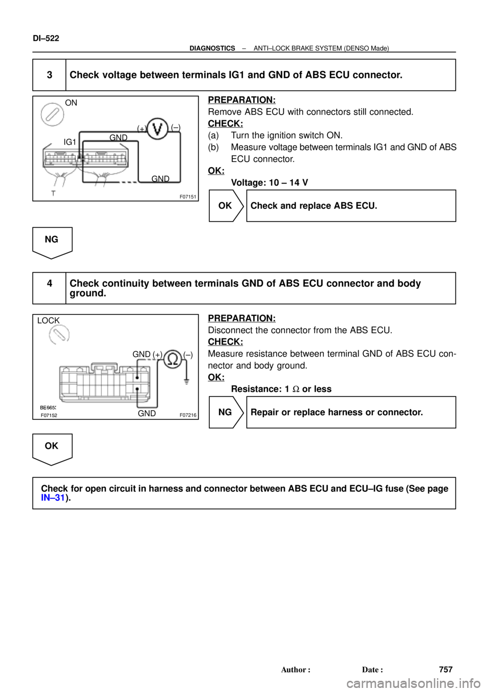
3 Check voltage between terminals IG1 and GND of ABS ECU connector.
PREPARATION:
Remove ABS ECU with connectors still connected.
CHECK:
(a) Turn the ignition switch ON.
(b) Measure voltage between terminals IG1 and GND of ABS
ECU connector.
OK:
Voltage: 10 ± 14 V
OK Check and replace ABS ECU.
NG
4 Check continuity between terminals GND of ABS ECU connector and body
ground.
PREPARATION:
Disconnect the connector from the ABS ECU.
CHECK:
Measure resistance between terminal GND of ABS ECU con-
nector and body ground.
OK:
Resistance: 1 W or less
NG Repair or replace harness or connector.
OK
Check for open circuit in harness and connector between ABS ECU and ECU±IG fuse (See page
IN±31).
 (±) ON
(+) (±)
± DIAGNOSTICSAUTOMATIC TRANSAXLE (A541")