Page 1653 of 4592

DI±441
676 Author�: Date�:
3. INSPECT DIAGNOSIS (CHECK MODE)
HINT:
TOYOTA hand±held te")
S05335
TOYOTA hand±held tester
DLC3
BR3904
ON
OFF0.13 sec.
0.13 sec.
± DIAGNOSTICSAUTOMATIC TRANSAXLE (A541E)
DI±441
676 Author�: Date�:
3. INSPECT DIAGNOSIS (CHECK MODE)
HINT:
TOYOTA hand±held tester only: Compared to the normal
mode, the check mode has high sensing ability to detect mal-
functions. Furthermore, the same diagnostic items which are
detected in Normal mode can also be detected in Check mode.
(a) Check the DTC.
(1) Check the initial conditions.
�Battery positive voltage 11 V or more.
�Throttle valve fully closed.
�Transaxle in P position.
�Air conditioning switched off.
(2) Turn the ignition switch OFF.
(3) Prepare a TOYOTA hand±held tester.
(4) Connect the TOYOTA hand±held tester to DLC3 at
the lower of the instrument panel.
(5) Turn the ignition switch ON and switch the TOYOTA
hand±held tester ON.
(6) Switch the TOYOTA hand±held tester from Normal
mode to Check mode (Check that the MIL flashes).
(7) Start the engine (MIL goes out after the engine
starts).
(8) Simulate the conditions of the malfunction de-
scribed by the customer.
NOTICE:
Leave the ignition switch ON until you have checked the
DTCs, etc..
(9) After simulating the malfunction conditions, use the
TOYOTA hand±held tester diagnosis selector to
check the DTCs and freeze frame data, etc..
HINT:
Take care not to turn the ignition switch OFF, as turning it off
switches the diagnosis system from Check mode to Normal
mode, so all DTCs, etc. are erased.
(10) After checking the DTC, inspect the applicable cir-
cuit.
Page 1670 of 4592
BE6653P23876D01908D02281
ON
SPD
(±)(+)
(±)
(+)
SPD Except California, w/ Engine
Immobilizer and / or TRAC:
California, w/ Engine Immobilizer
and / or TRAC:
DI±458
± DIAGNOSTICSAUTOMATIC TRANSAXLE (A541E)
693 Author�: Date�:
3 Check voltage between terminal SPD of ECM connector and body ground.
PREPARATION:
Turn ignition switch ON.
CHECK:
Measure voltage between terminal SPD of ECM connector and
body ground.
OK:
Voltage: 9 ~ 14 V
NG Check for open in harness and connector be-
tween junction connector (J15) and ECM (See
page IN±31).
OK
4 Check for open in harness and connector between junction connector (J15) and
combination meter (See page IN±31).
NG Repair or replace harness or connector.
OK
Page 1692 of 4592

D01897
Combination Meter
Ignition Switch Except California, w/ Engine Immobilizer and / or TRAC:
R
2
L8
11
6 C8
13
165
R±B
L±W YIJ1
IG310
1H
1VECM
1
E7
B+ 4
II2 P1
II3D J/C J2910 C8
C8O
Y
R±BY
R 2L
E7
E7
E10 II2 P1
P1
P1D D
J/C J29 E
15
14
B±W A
GR3
6CL±W (*1, *3)
O (*2, *4) LL
2L
RL R±L
J27J28
J/C
10FE E Y
Y
L±W L±W6 5
8
R±BR±BR±B
5
P1 P12
AJ/C
J24
R±LA J27
C
B±W
B
BB
J/C J26
B±W
II2II22
R±L
J28J/C J28
F
J2811
II2
B±WBBJ/C J29NSW
R±L
B±W 1
1
GAUGE
1K 1J I16 I16
I16 I16
1J 1K3
4 Starter B±Y
R 4
8 2
7IG1
AM1
ST2
AM2 1B
2L 2AW
W±R 2
1K AM1
2 1 1
1B 1K5 5
GR (*4)
B±O (*5)
W±R
41
AM2
B
B B±R
B±R
B±R
1
2 F9
F9
ALT
11F4
F6
B±G
BatteryB
C
J8J7GR (*4)
B±O (*5)3
1
2535
2B
2D
2J
2K 11
12
ST
Relay
B±R
Starter
W±BAJ/C J11
IG
Left Kick
Panel Park/Neutral Position Switch
9
J/C CInstrument Panel J/B
Fusible
Link BlockEngine Room J/B No.2
MAIN 3
FL
Main
*1: w/ Engine Immobilizer System
*2: w/o Engine Immobilizer System
*3: TMC Made Ex. USA w/ TRAC
*4: TMMK Made, TMC Made USA w/ TRAC DI±480
± DIAGNOSTICSAUTOMATIC TRANSAXLE (A541E)
715 Author�: Date�:
WIRING DIAGRAM
Page 1693 of 4592

D01898
Combination Meter
Ignition Switch California, w/ Engine Immobilizer and / or TRAC:
R
2
L8
11
6 C8
13
165
R±B
L±W YIJ1
IG310
1H 1VECM
12
B+ 4
II2 P1
II3D J/C J29 C8
C8O
Y
R±BY
R 2 L
II2
P1
P1
P1D D
J/C J29 E
20
B±W A
GR3
6L±W (*1, *3)
O (*2, *4) LL
2L
RL R±L
J27J28
J/C
10FE E
Y Y
L±W L±W65
8
R±B
R±BR±B
5
P1P12
AJ/C
J24
R±LJ27
B±W
BB
II2II22
R±L
J28J/C J28
F
J28J/C J29NSW
R±L
B±W 1 1
GAUGE
1K1J
I16I16
I16 I16 1J1K3 4
Starter B±Y
R 4
8 2
7IG1
AM1
ST2
AM2 1B
2L 2AW
W±R 2
1K AM1
2 1 1
1B1K5 5
GR (*4)
B±O (*5)
W±R
41
AM2
B
B B±R
B±R
B±R
12
F9 F9
ALT
11
F4F6
B±G
FL
Main
BatteryF
J8
J7GR (*4)
B±O (*5)3
12535
2B
2D
2J2K 11
12
ST
Relay
B±R
Starter
W±BAJ/C J11
IG
Left Kick
Panel *1: w/ Engine Immobilizer System
*2: w/o Engine Immobilizer System
*3: TMC Made Ex. USA w/ TRAC
*4: TMMK Made, TMC Made USA w/ TRAC Park/Neutral Position SwitchE8
3
2
B±W B B
J/C J26II2 11
B±W
B
C9
J/C C
E8
E8E8
3C
CA
Engine Room J/B No.2
MAINInstrument Panel J/B
Instrument Panel J/B
Fusible
Link Block
± DIAGNOSTICSAUTOMATIC TRANSAXLE (A541E)
DI±481
716 Author�: Date�:
Page 1694 of 4592

BE3840D00052D00836D01914
Except California, w/ Engine Immobilizer
and / or TRAC:
California, w/ Engine Immobilizer
and / or TRAC:ON
L
NSW
2
R
2R
L
NSW
Position
P, N
R
D
2
LNSW±Body
groundR±Body
ground2±Body
groundL±Body
ground
0 V
0 V0 V0 V
0 V
0 V
0 V 0 V
0 V
0 V 0 V
0 V
0 V 9 ~ 14 V*
9 ~ 14 V
9 ~ 14 V
9 ~ 14 V9 ~ 14 V
9 ~ 14 V 9 ~ 14 V* DI±482
± DIAGNOSTICSAUTOMATIC TRANSAXLE (A541E)
717 Author�: Date�:
INSPECTION PROCEDURE
1 Read PNP, REVERSE, 2ND and LOW signals.
When using TOYOTA hand±held tester.
PREPARATION:
(a) Remove the DLC3 cover.
(b) Connect a TOYOTA hand±held tester to the DLC3.
(c) Turn the ignition switch ON and TOYOTA hand±held tes-
ter main switch ON.
CHECK:
Shift lever into the P, R, N, 2 and L positions, and read the PNP,
REVERSE, 2ND and LOW signals on the TOYOTA hand±held
tester.
OK:
Shift positionSignal
22ND OFF " ON
LLOW OFF " ON
RREVERSE OFF " ON
P, NNSW OFF " ON
When not using TOYOTA hand±held tester.
PREPARATION:
Turn the ignition switch ON.
CHECK:
Measure voltage between terminals NSW, 2, L and R of ECM
and body ground when the shift lever is shifted to the following
positions.
OK:
HINT:
*: The voltage will drop slightly due to lighting up of the back up
light.
Page 1697 of 4592
BE3840Q07659
D00053
D00835D01915
Except California, w/ Engine Immobilizer
and / or TRAC:
California, w/ Engine Immobilizer
and / or TRAC:OD1
OD1 ON
(+) (±) (±)
(+)
± DIAGNOSTICSAUTOMATIC TRANSAXLE (A541E)
DI±485
720 Author�: Date�:
INSPECTION PROCEDURE
1 Check voltage between terminal OD1 of ECM and body ground.
PREPARATION:
Turn the ignition switch ON.
CHECK:
Measure voltage between terminal OD1 of ECM and body
ground.
OK:
Voltage: 10 ~ 14 V
OK Proceed to next circuit inspection shown on
matrix chart (See page DI±453).
NG
Page 1698 of 4592
AB0119
N19917
I00742
ON
O/D
(±)
(+)
DI±486
± DIAGNOSTICSAUTOMATIC TRANSAXLE (A541E)
721 Author�: Date�:
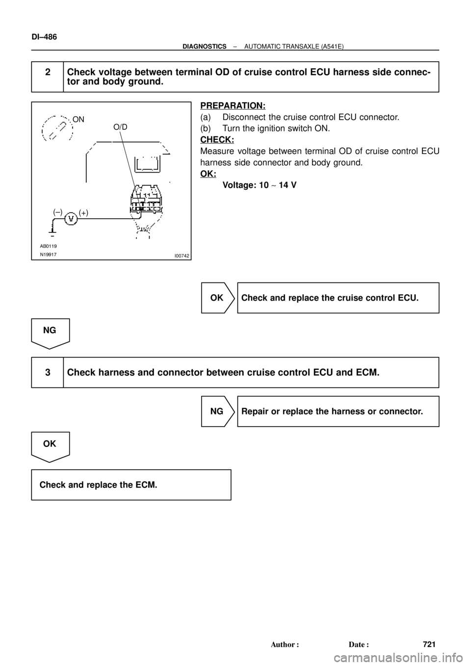
2 Check voltage between terminal OD of cruise control ECU harness side connec-
tor and body ground.
PREPARATION:
(a) Disconnect the cruise control ECU connector.
(b) Turn the ignition switch ON.
CHECK:
Measure voltage between terminal OD of cruise control ECU
harness side connector and body ground.
OK:
Voltage: 10 ~ 14 V
OK Check and replace the cruise control ECU.
NG
3 Check harness and connector between cruise control ECU and ECM.
NG Repair or replace the harness or connector.
OK
Check and replace the ECM.
Page 1699 of 4592
D01900
ECM
4E7OD2B+
G±O
IG1 C
CC
O2 O/D Main
Switch O/D Indicator
Light
C8 712
R±L
D
Ignition Switch
11K2
1DGAUGE J/C J4
G±OG±O
IG3
J/C J6
G±O
O2
B±Y
AM11B 1K
C10
AM1
F9 D
R±L
I16 W 21
24
I16 2
12
B±R
B±R
B±R1
2
F9Fusible Link Block
FL Main
Battery 1
F4B±GW±B
A
J/C J5
IF A
W±B
Left Kick Panel
*1: Except California, w/ Engine Immobilizer and / or TRAC
*2: California, w/ Engine Immobilizer and / or TRACInstrument Panel J/B
Instrument Panel J/B11106 *2*1
ALTE8
± DIAGNOSTICSAUTOMATIC TRANSAXLE (A541E)
DI±487
722 Author�: Date�:
O/D Main Switch & O/D OFF Indictor Light Circuit
CIRCUIT DESCRIPTION
The O/D main switch contacts go open when the switch is pushed in and go closed when it is pushed out.
In O/D main switch at OFF position, the O/D OFF indicator light lights up, and the ECM prohibits shifting over-
drive.
WIRING DIAGRAM
DI1KD±01
(+)
(±)
(+)
SPD Except California, w/ Engine
Immobilizer and / or TRAC:
California, w/ Engine Immobilizer
and / or TRAC:
DI±458
± DIAGNOSTICSAUTOMATIC TRANSAXL")
 (±) (±)
(+)
± DIAGNOSTICSAUTOMATIC TRANSAXLE")