Page 1468 of 4592

491 Author�: Date�:
HINT:
If a malfunction exists, the MIL will light up during step (6).
NOTICE:
If the conditions in this test are not strictly followed")
P18349
DI±256
± DIAGNOSTICSENGINE (1MZ±FE)
491 Author�: Date�:
HINT:
If a malfunction exists, the MIL will light up during step (6).
NOTICE:
If the conditions in this test are not strictly followed, detection of the malfunction will not be possible.
If you do not have a TOYOTA hand±held tester, turn the ignition switch OFF after performing steps
(3) to (6), then perform steps (3) to (6) again.
INSPECTION PROCEDURE
HINT:
Read freeze frame data using TOYOTA hand±held tester or OBD II scan tool. Because freeze frame records
the engine conditions when the malfunction is detected, when troubleshooting it is useful for determining
whether the vehicle was running or stopped, the engine warmed up or not, the air±fuel ratio lean or rich, etc.
at the time of the malfunction.
1 Are there any other codes (besides DTC P0130, P0150) being output ?
YES Go to relevant DTC chart.
NO
2 Check the output voltage of heated oxygen sensors (bank1, 2 sensor1)
during idling.
PREPARATION:
Warm up the heated oxygen sensors (bank1, 2 sensor1) with the engine at 2,500 rpm for approx. 90 sec.
CHECK:
Use the OBD II scan tool or TOYOTA hand±held tester to read the output voltage of the heated oxygen sen-
sors (bank1, 2 sensor1) during idling.
OK:
Heated oxygen sensors (bank1, 2 sensor1) output voltage:
Alternates repeatedly between less than 0.4 V and more than 0.55 V (See the following table).
OK Go to step 8.
NG
Page 1476 of 4592
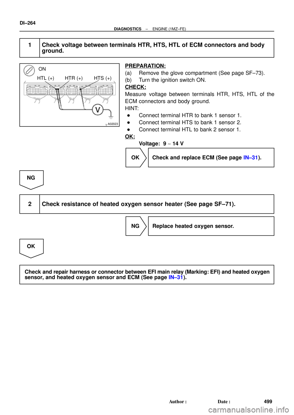
A02023
ON
HTL (+) HTR (+) HTS (+)
DI±264
± DIAGNOSTICSENGINE (1MZ±FE)
499 Author�: Date�:
1 Check voltage between terminals HTR, HTS, HTL of ECM connectors and body
ground.
PREPARATION:
(a) Remove the glove compartment (See page SF±73).
(b) Turn the ignition switch ON.
CHECK:
Measure voltage between terminals HTR, HTS, HTL of the
ECM connectors and body ground.
HINT:
�Connect terminal HTR to bank 1 sensor 1.
�Connect terminal HTS to bank 1 sensor 2.
�Connect terminal HTL to bank 2 sensor 1.
OK:
Voltage: 9 ~ 14 V
OK Check and replace ECM (See page IN±31).
NG
2 Check resistance of heated oxygen sensor heater (See page SF±71).
NG Replace heated oxygen sensor.
OK
Check and repair harness or connector between EFI main relay (Marking: EFI) and heated oxygen
sensor, and heated oxygen sensor and ECM (See page IN±31).
Page 1481 of 4592
± DIAGNOSTICSENGINE (1MZ±FE)
DI±269
504 Author�: Date�:
4 Check for spark and ignition (See page IG±1).
NG Repair or replace.
OK
5 Check fuel pressure (See page SF±21).
NG Check and repair fuel pump, pressure regulator,
fuel pipe line and filter (See page SF±1).
OK
6 Check gas leakage on exhaust system.
NG Repair or replace.
OK
Page 1485 of 4592
± DIAGNOSTICSENGINE (1MZ±FE)
DI±273
508 Author�: Date�:
1 Check air induction system (See page SF±1).
NG Repair or replace.
OK
2 Check injector injection (See page SF±21).
NG Replace injector.
OK
3 Check mass air flow meter and engine coolant temp. sensor
(See pages SF±35 and SF±63).
NG Repair or replace.
OK
4 Check for spark and ignition (See page IG±1).
NG Repair or replace.
OK
5 Check fuel pressure (See page SF±6).
NG Check and repair fuel pump, pressure regulator,
fuel pipe line and filter.
OK
Page 1488 of 4592

511 Author�: Date�:
DTC P0300 Random/Multiple Cylinder Misfire Detected
DTC P0301 Cylinder 1 Misfire Detected
DTC P0302 Cylinder 2 Misfire Detected
DTC P0303 Cyl")
DI±276
± DIAGNOSTICSENGINE (1MZ±FE)
511 Author�: Date�:
DTC P0300 Random/Multiple Cylinder Misfire Detected
DTC P0301 Cylinder 1 Misfire Detected
DTC P0302 Cylinder 2 Misfire Detected
DTC P0303 Cylinder 3 Misfire Detected
DTC P0304 Cylinder 4 Misfire Detected
DTC P0305 Cylinder 5 Misfire Detected
DTC P0306 Cylinder 6 Misfire Detected
CIRCUIT DESCRIPTION
Misfire: The ECM uses the crankshaft position sensor and camshaft position sensor to monitor changes in
the crankshaft rotation for each cylinder.
The ECM counts the number of times the engine speed change rate indicates that misfire has occurred.
When the misfire rate equals or exceeds the count indicating that the engine condition has deteriorated, the
MIL lights up.
If the misfire rate is high enough and the driving conditions will cause catalyst overheating, the MIL blinks
when misfiring occurs.
DTC No.DTC Detecting ConditionTrouble Area
P0300Misfiring of random cylinders is detected during any
particular 200 or 1,000 revolutions�Ignition system
�Injector
�Fuel line pressure
P0301
P0302
P0303For any particular 200 revolutions for engine, misfiring is de-
tected which can cause catalyst overheating
(This causes MIL to blink)
�EGR
�Compression pressure
�Valve clearance not to specification
�Valve timing
�Mass air flow meterP0303
P0304
P0305
P0306For any particular 1,000 revolutions of engine, misfiring is de-
tected which causes a deterioration in emission
(2 trip detection logic)
�Mass air flow meter
�Engine coolant temp. sensor
�Open or short in engine wire
�Connector connection
�ECM
DI07S±07
Page 1489 of 4592

A03319
Instrument
Panel J/B
Engine
Room
J/B
N0.2
BatteryFL
MAINB±GB±R B±R
B±R
W±RJ18
Junction
Connector
B±R
B±R
B±R
B±R
B±R
B±R2
2
2
2
2
21
1
1
1
1
1L
R
Y
W
R±L
GE10
Ignition
Switch
No. 1
No. 2
No. 3
No. 4
No. 5
No. 6
Injector
BR
BR
EC
II3
5
6
21
311
2
3
4#10
#20
#30
#40
#50
#60
E01
E02ECM
12
2L
2A
AM2
4
1
B
F4F6 11 6
7
1K 1K 1C
1B 38
55
W±RE10
E11
E11
E11
E11
E11
E11 Fusible
Link
Block
± DIAGNOSTICSENGINE (1MZ±FE)
DI±277
512 Author�: Date�:
HINT:
When the 2 or more codes for a misfiring cylinder are recorded repeatedly but no Random Misfire code is
recorded, it indicates that the misfires were detected and recorded at different times.
WIRING DIAGRAM
CONFIRMATION DRIVING PATTERN
(1) Connect the TOYOTA hand±held tester or OBD II scan tool.
(2) Record DTC and the freeze frame data.
(3) Use the TOYOTA hand±held tester to set to Check Mode. (See page DI±197)
(4) Drive the vehicle several times with the engine speed, load and its surrounding range shown with
ENGINE SPD, CALC LOAD in the freeze frame data or MISFIRE RPM, MISFIRE LOAD in the data list.
If you have no TOYOTA hand±held tester, turn the ignition switch OFF after the symptom is simulated
the first time. Then repeat the simulation process again.
HINT:
In order to memorize DTC of misfire, it is necessary to drive around MISFIRE RPM, MISFIRE LOAD in the
data list for the following period of time.
Engine SpeedTime
Idling3 minutes 30 seconds or more
1000 rpm3 minutes or more
2000 rpm1 minute 30 seconds or more
3000 rpm1 minute or more
(5) Check whether there is misfire or not by monitoring DTC and the freeze frame data. After that, record
them.
(6) Turn ignition switch OFF and wait at least 5 seconds.
Page 1490 of 4592

513 Author�: Date�:
INSPECTION PROCEDURE
HINT:
�If is the case that DTC besides misfire is memorized simultaneously, first perform the troubleshooting
for them.")
DI±278
± DIAGNOSTICSENGINE (1MZ±FE)
513 Author�: Date�:
INSPECTION PROCEDURE
HINT:
�If is the case that DTC besides misfire is memorized simultaneously, first perform the troubleshooting
for them.
�Read freeze frame data using TOYOTA hand±held tester or OBD II scan tool. Because freeze frame
data records the engine conditions when the malfunction is detected, when troubleshooting it is useful
for determining whether the vehicle was running or stopped, the engine warmed up or not, the air±fuel
ratio lean or rich, etc. at the time of the malfunction.
�When the vehicle is brought to the workshop and the misfire is not occurred, misfire can be confirmed
by reproducing the condition or freeze frame data. Also, after finishing the repair, confirm that there
is no misfire. (See the confirmation driving pattern)
�When either of SHORT FT #1, LONG FT #1, SHORT FT #2 or LONG FT #2 in the freeze frame data
is besides the range of ±20%, there is a possibility that the air±fuel ratio is inclining either to ºrichº
(±20% or less) or ºleanº (+20% or more).
�When COOLANT TEMP in the freeze frame data is less than 80°C (176°F), there is a possibility or
misfire only during warming up.
�In the case that misfire cannot be reproduced, the reason may be because of the driving with lack or
fuel, the use of improper fuel, a stain of ignition plug, and etc.
1 Check wire harness, connector and vacuum hose in engine room.
CHECK:
(a) Check the connection conditions of wire harness and connector.
(b) Check the disconnection, piping and break of vacuum hose.
NG Repair or replace, then confirm that there is no
misfire (See the confirmation driving pattern).
OK
Page 1491 of 4592

DI±279
514 Author�: Date�:
2 Check spark plug and spark of misfiring cylinder.
PREPARATION:
(a) Remove the ignition coil (See page IG±7).
(b) Remov")
A00221P25779
P23917
± DIAGNOSTICSENGINE (1MZ±FE)
DI±279
514 Author�: Date�:
2 Check spark plug and spark of misfiring cylinder.
PREPARATION:
(a) Remove the ignition coil (See page IG±7).
(b) Remove the spark plug.
CHECK:
(a) Check spark plug type.
(b) Check for carbon deposits on electrode.
(c) Check electrode gap.
OK:
(a) Twin ground electrodes type.
Recommended spark plug:
ND PK20TR11
NGK BKR6EKPB±11
(b) No large carbon deposit present.
Not wet with gasoline or oil.
(c) Electrode gap:
Standerd: 1.0 ± 1.1 mm (0.03937 ± 0.043 in.).
Maximum: 1.3 mm (0.051 in.).
PREPARATION:
(a) Install the spark plug to the ignition coil, and connect the
ignition coil the connector.
(b) Disconnect injector connector.
(c) Hold the end about 12.5 mm (0.5 in.) from the ground.
CHECK:
Check if spark occurs while engine is being cranked.
NOTICE:
To prevent excess fuel being injected from the
injectors during this test, don't crank the engine for more
than 5 ~ 10 sec. at a time.
OK:
Spark jumps across electrode gap.
NG Replace or check ignition system
(See page IG±1).
OK