Page 1492 of 4592
A02024
ON
#10 #20 #30 #40 #50 #60(+) (+) (+) (+) (+) (+)
FI6588
FI6538
A00064
10 V
/Division10 V
/Division
GND GND
100 msec./Division (Idling)1 msec./Division (Idling)
Injection duration
(Magnification)
DI±280
± DIAGNOSTICSENGINE (1MZ±FE)
515 Author�: Date�:
3 Check voltage of ECM terminal for injector of failed cylinder.
PREPARATION:
(a) Remove the glove compartment (See page SF±73).
(b) Turn the ignition switch ON.
CHECK:
Measure voltage between applicable terminal of the ECM con-
nector and body ground.
OK:
Voltage: 9 ~ 14 V
Reference INSPECTION USING OSCILLOSCOPE
INJECTOR SIGNAL WAVEFORM
With the engine idling, measure between terminals #10 ~ #60 and E01 of ECM.
HINT:
The correct waveform is as shown.
OK Go to step 5.
NG
Page 1495 of 4592

Knock Sensor 2
(On left bank)EC1 1W
W1
2W
WECM
KNKR
KNKLE1
E1 EC1 1E11
E112827
± DIAGNOSTICSENGINE (1MZ±FE)
DI±283
518 Author�: Date�:
DTC P0325 Knock Sensor 1")
A03315
Knock Sensor 1
(On right bank)
Knock Sensor 2
(On left bank)EC1 1W
W1
2W
WECM
KNKR
KNKLE1
E1 EC1 1E11
E112827
± DIAGNOSTICSENGINE (1MZ±FE)
DI±283
518 Author�: Date�:
DTC P0325 Knock Sensor 1 Circuit Malfunction
DTC P0330 Knock Sensor 2 Circuit Malfunction
CIRCUIT DESCRIPTION
Knock sensors are fitted one to the right bank and left bank of the cylinder block to detect engine knocking.
This sensor contains a piezoelectric element which generates a voltage when it becomes deformed, which
occurs when the cylinder block vibrates due to knocking. If engine knocking occurs, ignition timing is retarded
to suppress it.
DTC No.DTC Detecting ConditionTrouble Area
P0325No knock sensor 1 signal to ECM with engine speed between
2,000 rpm and 5,600 rpm.�Open or short in knock sensor 1 circuit
�Knock sensor 1 (looseness)
�ECM
P0330No knock sensor 2 signal to ECM with engine speed between
2,000 rpm and 5,600 rpm.�Open or short in knock sensor 2 circuit
�Knock sensor 2 (looseness)
�ECM
If the ECM detects the above diagnosis conditions, it operates the fail±safe function in which the corrective
retard angle value is set to the maximum value.
WIRING DIAGRAM
DI07T±06
Page 1496 of 4592

519 Author�: Date�:
INSPECTION PROCEDURE
HINT:
�DTC P0325 is for the")
A00304
Knock SensorECM
EC1
Male
ConnectorFemale
Connector 1
1
11
22KNKR
KNKL
EC1
E6
E627
28
DI±284
± DIAGNOSTICSENGINE (1MZ±FE)
519 Author�: Date�:
INSPECTION PROCEDURE
HINT:
�DTC P0325 is for the right bank knock sensor circuit. DTC P0330 is for the left bank knock sensor cir-
cuit.
�Read freeze frame data using TOYOTA hand±held tester or OBD II scan tool. Because freeze frame
records the engine conditions when the malfunction is detected, when troubleshooting it is useful for
determining whether the vehicle was running or stopped, the engine warmed up or not, the air±fuel
ratio lean or rich, etc. at the time of the malfunction.
1 Connect OBD II scan tool or TOYOTA hand±held tester, and check knock sensor
circuit.
PREPARATION:
(a) Connect the OBD II scan tool or TOYOTA hand±held tes-
ter to the DLC3.
(b) Disconnect the wire to wire connector EC1.
(c) Connect the terminals of the disconnected EC1 male con-
nector and EC1 female as follows.
Male connector eFemale connector
Terminal 1 e Terminal 2
Terminal 2 e Terminal 1
(d) Turn the ignition switch ON and push the OBD II scan tool
or TOYOTA hand±held tester main switch ON.
(e) After the engine is warmed up, perform quick racing to
4,000 rpm three times.
CHECK:
Check the DTC.
RESULT:
Type IDTC same as when vehicle brought in.
P0325 " P0325 or P0330 " P0330
Type IIDTC different to when vehicle brought in.
P0325 " P0330 or P0330 " P0325
Page 1506 of 4592

529 Author�: Date�:
(1) Connect the OBD II scan tool or TOYOTA hand±held tester to the DLC3.
(2) Start and warm up the engine with all accessories switched OFF.")
DI±294
± DIAGNOSTICSENGINE (1MZ±FE)
529 Author�: Date�:
(1) Connect the OBD II scan tool or TOYOTA hand±held tester to the DLC3.
(2) Start and warm up the engine with all accessories switched OFF.
(3) Run the vehicle at 70 ~ 90 km/h (43 ~ 56 mph) for 3 min. or more.
(4) Idle the engine for about 2 min.
(5) Do steps (3) and (4) again.
(6) Stop at safe place and turn the ignition switch OFF.
(7) Do step (2) to (5) again.
(8) Check the READINESS TESTS mode on the OBD II scan tool or TOYOTA hand±held tester.
If COMPL is displayed and the MIL does not light up, the system is normal.
If INCMPL is displayed and the MIL does not light up, run the vehicle steps (2) to (6) from some times and
check it.
HINT:
INCMPL is displayed when either condition (a) or (b) exists.
(a) The system check is incomplete.
(b) There is a malfunction in the system.
If there is a malfunction in the system, the MIL light up after step (7) above is done.
(2trip detection logic)
INSPECTION PROCEDURE
HINT:
Read freeze frame data using TOYOTA hand±held tester or OBD II scan tool. Because freeze frame records
the engine conditions when the malfunction is detected, when troubleshooting it is useful for determining
whether the vehicle was running or stopped, the engine warmed up or not, the air±fuel ratio lean or rich, etc.
at the time of the malfunction.
TOYOTA hand±held tester
1 Connect TOYOTA hand±held tester, and read value of EGR gas temperature.
PREPARATION:
(a) Connect the TOYOTA hand±held tester to the DLC3.
(b) Warm up the engine.
CHECK:
Read EGR gas temperature on TOYOTA hand±held tester during idling.
OK:
EGR gas temperature : 55C (415F) ~ 1505C (3025F) (Not immediately after driving)
HINT:
If there is an open circuit, TOYOTA hand±held tester indicates 3.15C (37.65F).
If there is an short circuit, TOYOTA hand±held tester indicates 159.35C (318.75F).
OK Go to step 4.
NG
Page 1507 of 4592
A00305
ON
ON EGR Gas Temp.
Sensor
EGR Gas Temp.
SensorECM
ECM
5 V
5 V
E2
E2
1
2
1
2
THG
THG18 13
E10
E10
E10E10
13
18
± DIAGNOSTICSENGINE (1MZ±FE)
DI±295
530 Author�: Date�:
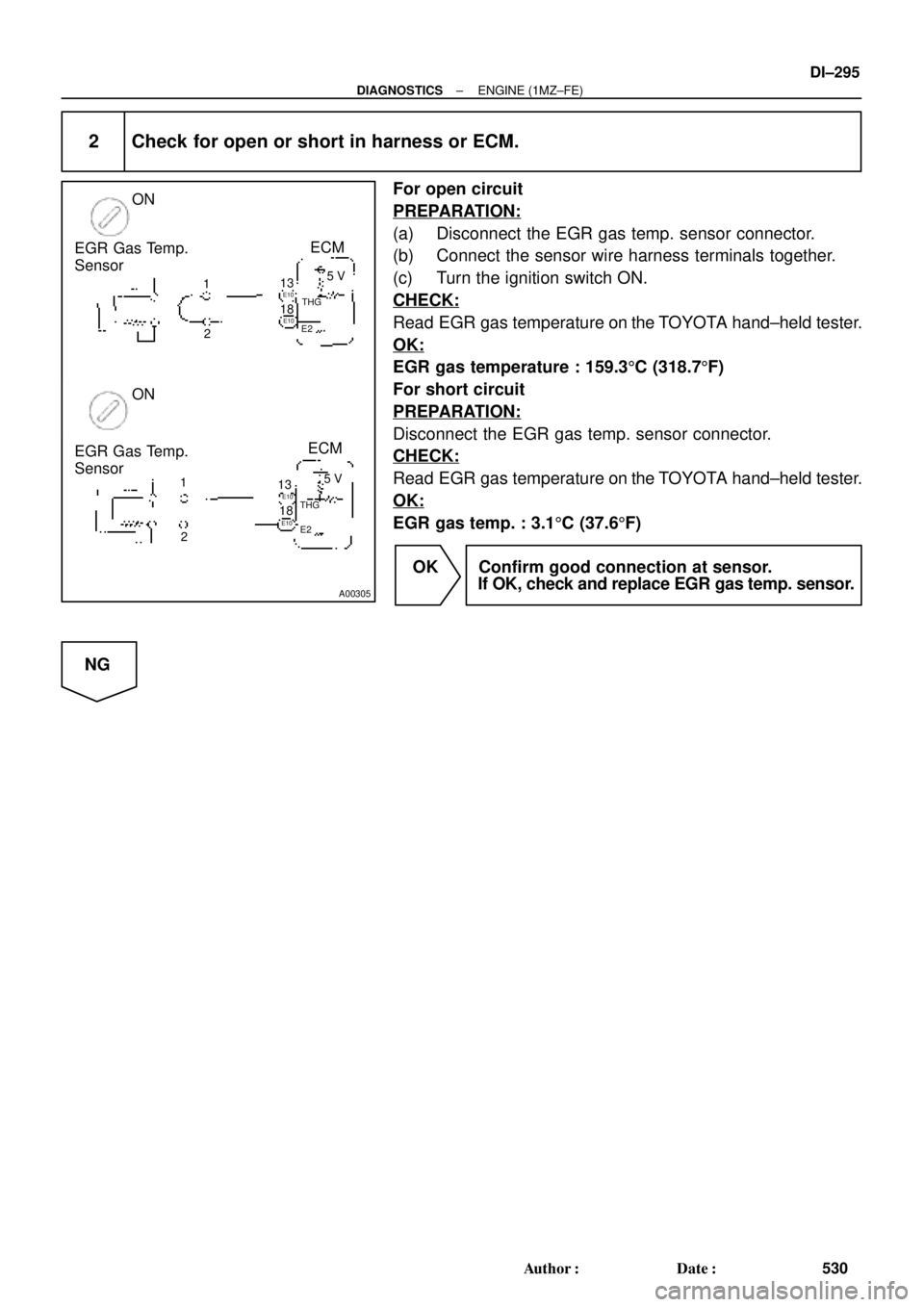
2 Check for open or short in harness or ECM.
For open circuit
PREPARATION:
(a) Disconnect the EGR gas temp. sensor connector.
(b) Connect the sensor wire harness terminals together.
(c) Turn the ignition switch ON.
CHECK:
Read EGR gas temperature on the TOYOTA hand±held tester.
OK:
EGR gas temperature : 159.35C (318.75F)
For short circuit
PREPARATION:
Disconnect the EGR gas temp. sensor connector.
CHECK:
Read EGR gas temperature on the TOYOTA hand±held tester.
OK:
EGR gas temp. : 3.15C (37.65F)
OK Confirm good connection at sensor.
If OK, check and replace EGR gas temp. sensor.
NG
Page 1512 of 4592
A02047
ON
EGR
ONOFF
VSV is ON VSV is OFF
G
E11
Air
FG Air
F EE
DI±300
± DIAGNOSTICSENGINE (1MZ±FE)
535 Author�: Date�:
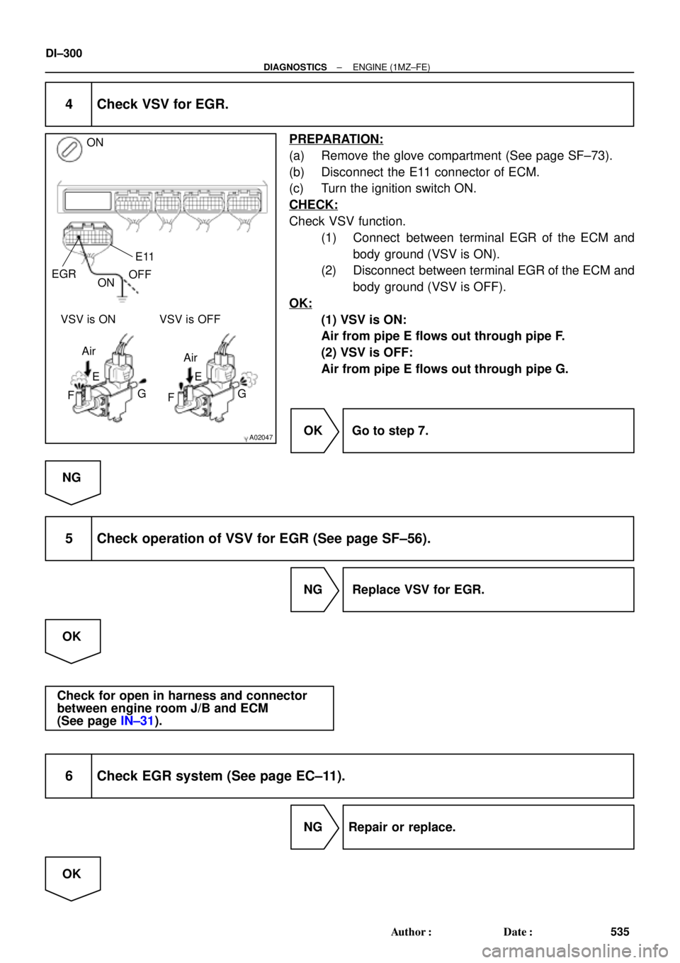
4 Check VSV for EGR.
PREPARATION:
(a) Remove the glove compartment (See page SF±73).
(b) Disconnect the E11 connector of ECM.
(c) Turn the ignition switch ON.
CHECK:
Check VSV function.
(1) Connect between terminal EGR of the ECM and
body ground (VSV is ON).
(2) Disconnect between terminal EGR of the ECM and
body ground (VSV is OFF).
OK:
(1) VSV is ON:
Air from pipe E flows out through pipe F.
(2) VSV is OFF:
Air from pipe E flows out through pipe G.
OK Go to step 7.
NG
5 Check operation of VSV for EGR (See page SF±56).
NG Replace VSV for EGR.
OK
Check for open in harness and connector
between engine room J/B and ECM
(See page IN±31).
6 Check EGR system (See page EC±11).
NG Repair or replace.
OK
Page 1527 of 4592
A02022
ON
VC (+) E2 (±)
± DIAGNOSTICSENGINE (1MZ±FE)
DI±315
550 Author�: Date�:
8 Check charcoal canister for cracks, hole and damage (See page EC±6).
NG Replace charcoal canister.
OK
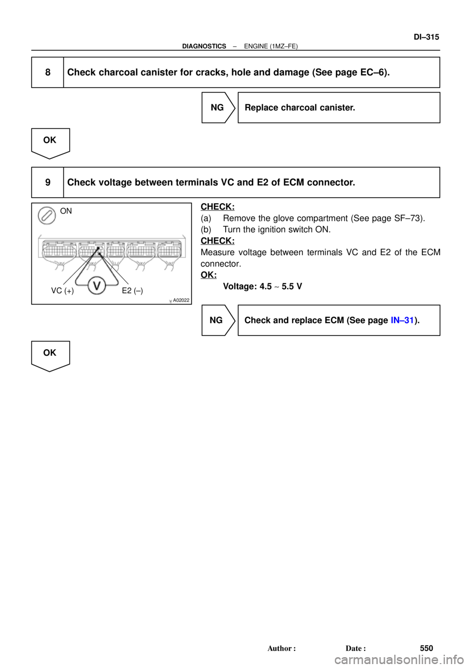
9 Check voltage between terminals VC and E2 of ECM connector.
CHECK:
(a) Remove the glove compartment (See page SF±73).
(b) Turn the ignition switch ON.
CHECK:
Measure voltage between terminals VC and E2 of the ECM
connector.
OK:
Voltage: 4.5 ~ 5.5 V
NG Check and replace ECM (See page IN±31).
OK
Page 1528 of 4592
A02025
ON
E2 (±) PTNK (+)
Vacuum (1) (2)
DI±316
± DIAGNOSTICSENGINE (1MZ±FE)
551 Author�: Date�:
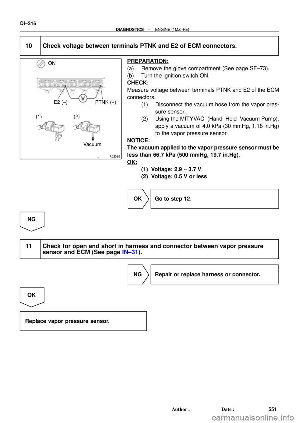
10 Check voltage between terminals PTNK and E2 of ECM connectors.
PREPARATION:
(a) Remove the glove compartment (See page SF±73).
(b) Turn the ignition switch ON.
CHECK:
Measure voltage between terminals PTNK and E2 of the ECM
connectors.
(1) Disconnect the vacuum hose from the vapor pres-
sure sensor.
(2) Using the MITYVAC (Hand±Held Vacuum Pump),
apply a vacuum of 4.0 kPa (30 mmHg, 1.18 in.Hg)
to the vapor pressure sensor.
NOTICE:
The vacuum applied to the vapor pressure sensor must be
less than 66.7 kPa (500 mmHg, 19.7 in.Hg).
OK:
(1) Voltage: 2.9 ~ 3.7 V
(2) Voltage: 0.5 V or less
OK Go to step 12.
NG
11 Check for open and short in harness and connector between vapor pressure
sensor and ECM (See page IN±31).
NG Repair or replace harness or connector.
OK
Replace vapor pressure sensor.
 (+) (+) (+) (+) (+)
FI6588
FI6538
A00064
10 V
/Division10 V
/Division
GND GND
100 msec./Division (Idling)1 msec./Division (Idling)
Injection duration")