1999 NISSAN PRIMERA wheel
[x] Cancel search: wheelPage 528 of 2267
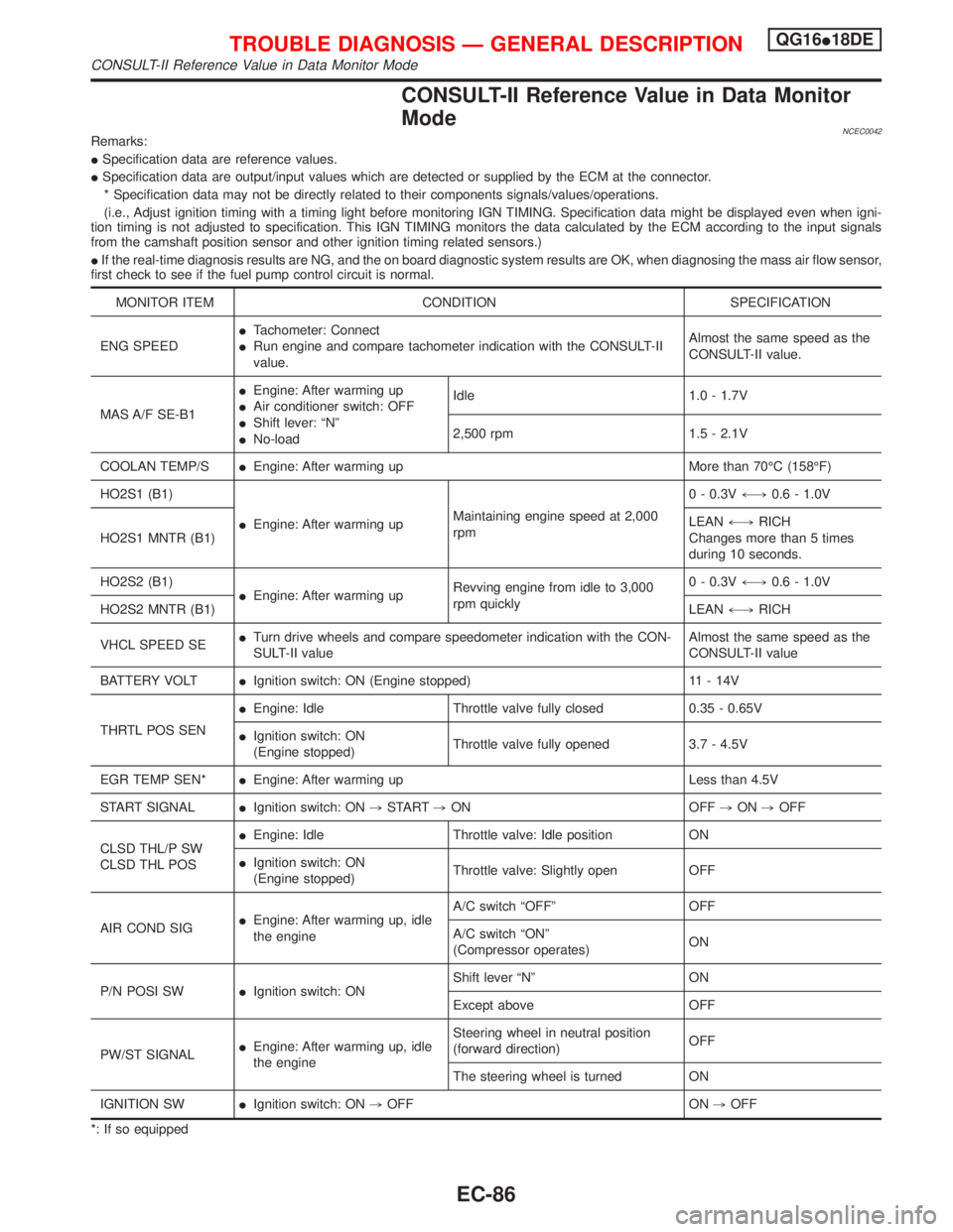
CONSULT-II Reference Value in Data Monitor
Mode
NCEC0042Remarks:
ISpecification data are reference values.
ISpecification data are output/input values which are detected or supplied by the ECM at the connector.
* Specification data may not be directly related to their components signals/values/operations.
(i.e., Adjust ignition timing with a timing light before monitoring IGN TIMING. Specification data might be displayed even when igni-
tion timing is not adjusted to specification. This IGN TIMING monitors the data calculated by the ECM according to the input signals
from the camshaft position sensor and other ignition timing related sensors.)
IIf the real-time diagnosis results are NG, and the on board diagnostic system results are OK, when diagnosing the mass air flow sensor,
first check to see if the fuel pump control circuit is normal.
MONITOR ITEM CONDITION SPECIFICATION
ENG SPEEDITachometer: Connect
IRun engine and compare tachometer indication with the CONSULT-II
value.Almost the same speed as the
CONSULT-II value.
MAS A/F SE-B1IEngine: After warming up
IAir conditioner switch: OFF
IShift lever: ªNº
INo-loadIdle 1.0 - 1.7V
2,500 rpm 1.5 - 2.1V
COOLAN TEMP/SIEngine: After warming up More than 70ÉC (158ÉF)
HO2S1 (B1)
IEngine: After warming upMaintaining engine speed at 2,000
rpm0 - 0.3V+,0.6 - 1.0V
HO2S1 MNTR (B1)LEAN+,RICH
Changes more than 5 times
during 10 seconds.
HO2S2 (B1)
IEngine: After warming upRevving engine from idle to 3,000
rpm quickly0 - 0.3V+,0.6 - 1.0V
HO2S2 MNTR (B1)LEAN+,RICH
VHCL SPEED SEITurn drive wheels and compare speedometer indication with the CON-
SULT-II valueAlmost the same speed as the
CONSULT-II value
BATTERY VOLTIIgnition switch: ON (Engine stopped) 11 - 14V
THRTL POS SENIEngine: Idle Throttle valve fully closed 0.35 - 0.65V
IIgnition switch: ON
(Engine stopped)Throttle valve fully opened 3.7 - 4.5V
EGR TEMP SEN*IEngine: After warming up Less than 4.5V
START SIGNALIIgnition switch: ON,START,ON OFF,ON,OFF
CLSD THL/P SW
CLSD THL POSIEngine: Idle Throttle valve: Idle position ON
IIgnition switch: ON
(Engine stopped)Throttle valve: Slightly open OFF
AIR COND SIGIEngine: After warming up, idle
the engineA/C switch ªOFFº OFF
A/C switch ªONº
(Compressor operates)ON
P/N POSI SWIIgnition switch: ONShift lever ªNº ON
Except above OFF
PW/ST SIGNALIEngine: After warming up, idle
the engineSteering wheel in neutral position
(forward direction)OFF
The steering wheel is turned ON
IGNITION SWIIgnition switch: ON,OFF ON,OFF
*: If so equipped
TROUBLE DIAGNOSIS Ð GENERAL DESCRIPTIONQG16I18DE
CONSULT-II Reference Value in Data Monitor Mode
EC-86
Page 529 of 2267
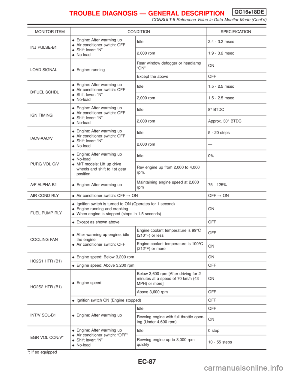
MONITOR ITEM CONDITION SPECIFICATION
INJ PULSE-B1IEngine: After warming up
IAir conditioner switch: OFF
IShift lever: ªNº
INo-loadIdle 2.4 - 3.2 msec
2,000 rpm 1.9 - 3.2 msec
LOAD SIGNALIEngine: runningRear window defogger or headlamp
ªONºON
Except the above OFF
B/FUEL SCHDLIEngine: After warming up
IAir conditioner switch: OFF
IShift lever: ªNº
INo-loadIdle 1.5 - 2.5 msec
2,000 rpm 1.5 - 2.5 msec
IGN TIMINGIEngine: After warming up
IAir conditioner switch: OFF
IShift lever: ªNº
INo-loadIdle 8É BTDC
2,000 rpm Approx. 30É BTDC
IACV-AAC/VIEngine: After warming up
IAir conditioner switch: OFF
IShift lever: ªNº
INo-loadIdle 5 - 20 steps
2,000 rpm Ð
PURG VOL C/VIEngine: After warming up
INo-load
IM/T models: Lift up drive
wheels and shift to 1st gear
position.Idle 0%
Rev engine up from 2,000 to 4,000
rpm.Ð
A/F ALPHA-B1IEngine: After warming upMaintaining engine speed at 2,000
rpm75 - 125%
AIR COND RLYIAir conditioner switch: OFF,ON OFF,ON
FUEL PUMP RLYIIgnition switch is turned to ON (Operates for 1 second)
IEngine running and cranking
IWhen engine is stopped (stops in 1.5 seconds)ON
IExcept as shown above OFF
COOLING FANIAfter warming up engine, idle
the engine.
IAir conditioner switch: OFFEngine coolant temperature is 99ÉC
(210ÉF) or lessOFF
Engine coolant temperature is 100ÉC
(212ÉF) or moreON
HO2S1 HTR (B1)IEngine speed: Below 3,200 rpm ON
IEngine speed: Above 3,200 rpm OFF
HO2S2 HTR (B1)IEngine speedBelow 3,600 rpm [After driving for 2
minutes at a speed of 70 km/h (43
MPH) or more]ON
Above 3,600 rpm OFF
IIgnition switch ON (Engine stopped) OFF
INT/V SOL-B1IEngine: After warming upIdle OFF
Revving engine with full throttle open-
ing (Under 4,600 rpm)ON
EGR VOL CON/V*IEngine: After warming up
IAir conditioner switch: ªOFFº
IShift lever: ªNº
INo-loadIdle 0 step
Revving engine up to 3,000 rpm
quickly10 - 55 steps
*: If so equipped
TROUBLE DIAGNOSIS Ð GENERAL DESCRIPTIONQG16I18DE
CONSULT-II Reference Value in Data Monitor Mode (Cont'd)
EC-87
Page 534 of 2267
![NISSAN PRIMERA 1999 Electronic Repair Manual TER-
MINAL
NO.WIRE
COLORITEM CONDITION DATA (DC Voltage)
1 Y/RIntake valve timing con-
trol solenoid valve[Engine is running]
IIdle speedBATTERY VOLTAGE
(11 - 14V)
[Engine is running]
ILift up drive w NISSAN PRIMERA 1999 Electronic Repair Manual TER-
MINAL
NO.WIRE
COLORITEM CONDITION DATA (DC Voltage)
1 Y/RIntake valve timing con-
trol solenoid valve[Engine is running]
IIdle speedBATTERY VOLTAGE
(11 - 14V)
[Engine is running]
ILift up drive w](/manual-img/5/57377/w960_57377-533.png)
TER-
MINAL
NO.WIRE
COLORITEM CONDITION DATA (DC Voltage)
1 Y/RIntake valve timing con-
trol solenoid valve[Engine is running]
IIdle speedBATTERY VOLTAGE
(11 - 14V)
[Engine is running]
ILift up drive wheels and shift gear ªONº
IRev engine up from 1,200 to 3,000 rpmApproximately 0V
3 W/RHeated oxygen sensor
2 heater (rear)[Engine is running]
IEngine speed is below 3,600 rpm
IAfter driving for 2 minutes at a speed of 70
km/h (43 MPH) or moreApproximately 0.7V
[Ignition switch ªONº]
IEngine stopped
IEngine speed is above 3,600 rpmBATTERY VOLTAGE
(11 - 14V)
4LHeated oxygen sensor
1 heater (front)[Engine is running]
IEngine speed is below 3,200 rpmApproximately 0V
[Engine is running]
IEngine speed is above 3,200 rpmBATTERY VOLTAGE
(11 - 14V)
6
7
15
16BR
Y/B
P
ORIACV-AAC valve[Engine is running]
IWarm-up condition
IIdle speed0.1 - 14V
8*
9*
17*
18*W/B
SB
G/R
R/YEGR volume control
valve[Engine is running]
IWarm-up condition
IRev engine up from 2,000 to 4,000 rpm0 - 14V
13 LG/R Cooling fan relay[Engine is running]
ICooling fan is not operatingBATTERY VOLTAGE
(11 - 14V)
[Engine is running]
ICooling fan is operatingApproximately 0V
14 P/BEVAP canister purge
volume control valve
(ON/OFF duty)[Engine is running]
IWarm-up condition
IAccelerator pedal depressed5 - 12V
SEF975W
21 B/P Fuel pump relay[Ignition switch ªONº]
IFor 1 second after turning ignition switch ªONº
[Engine is running]0-1V
[Ignition switch ªONº]
IMore than 1 second after turning ignition switch
ªONºBATTERY VOLTAGE
(11 - 14V)
22 OR/L Malfunction indicator[Ignition switch ªONº]0-1V
[Engine is running]
IIdle speedBATTERY VOLTAGE
(11 - 14V)
23 L/W Air conditioner relay[Engine is running]
IBoth A/C switch and blower switch are ªONºApproximately 0V
[Engine is running]
IA/C switch is ªOFFºBATTERY VOLTAGE
(11 - 14V)
*: If so equipped
TROUBLE DIAGNOSIS Ð GENERAL DESCRIPTIONQG16I18DE
ECM Terminals and Reference Value (Cont'd)
EC-92
Page 536 of 2267
![NISSAN PRIMERA 1999 Electronic Repair Manual TER-
MINAL
NO.WIRE
COLORITEM CONDITION DATA (DC Voltage)
44 GY Air conditioner switch[Engine is running]
IBoth air conditioner switch and blower switch
are ªONº (Compressor operates)Approximately 0V NISSAN PRIMERA 1999 Electronic Repair Manual TER-
MINAL
NO.WIRE
COLORITEM CONDITION DATA (DC Voltage)
44 GY Air conditioner switch[Engine is running]
IBoth air conditioner switch and blower switch
are ªONº (Compressor operates)Approximately 0V](/manual-img/5/57377/w960_57377-535.png)
TER-
MINAL
NO.WIRE
COLORITEM CONDITION DATA (DC Voltage)
44 GY Air conditioner switch[Engine is running]
IBoth air conditioner switch and blower switch
are ªONº (Compressor operates)Approximately 0V
[Engine is running]
IAir conditioner switch is ªOFFºApproximately 5V
46 PU/WPower steering oil pres-
sure switch[Engine is running]
ISteering wheel is fully turnedApproximately 0V
[Engine is running]
ISteering wheel is not turnedApproximately 5V
48 B ECM ground[Engine is running]
IIdle speedEngine ground
50 RElectrical load signal
(Headlamp
Rear defogger)[Engine is running]
IHeadlamp switch or rear defogger switch is
ªONºBATTERY VOLTAGE
(11 - 14V)
[Engine is running]
IHeadlamp switch and rear defogger switch are
ªOFFºApproximately 0V
51 LG/B Blower fan SW[Ignition switch ªONº]
IBlower fan switch is ªONºApproximately 0V
57 B ECM ground[Engine is running]
IIdle speedEngine ground
58 B Sensors' ground[Engine is running]
IWarm-up condition
IIdle speedApproximately 0V
61 B Mass air flow sensor[Engine is running]
IWarm-up condition
IIdle speed1.0 - 1.7V
[Engine is running]
IWarm-up condition
IEngine speed is 2,500 rpm1.5 - 2.1V
62 RHeated oxygen sensor
1 (front)[Engine is running]
IWarm-up condition
IEngine speed is 2,000 rpm0 - Approximately 0.7V
SEF008W
63 LHeated oxygen sensor
2 (rear)[Engine is running]
IAfter warming up to normal operating tempera-
ture and engine speed is 3,000 rpm0 - Approximately 1.0V
64 GIntake air temperature
sensor[Engine is running]Approximately 0 - 4.8V
Output voltage varies with
intake air temperature
TROUBLE DIAGNOSIS Ð GENERAL DESCRIPTIONQG16I18DE
ECM Terminals and Reference Value (Cont'd)
EC-94
Page 540 of 2267
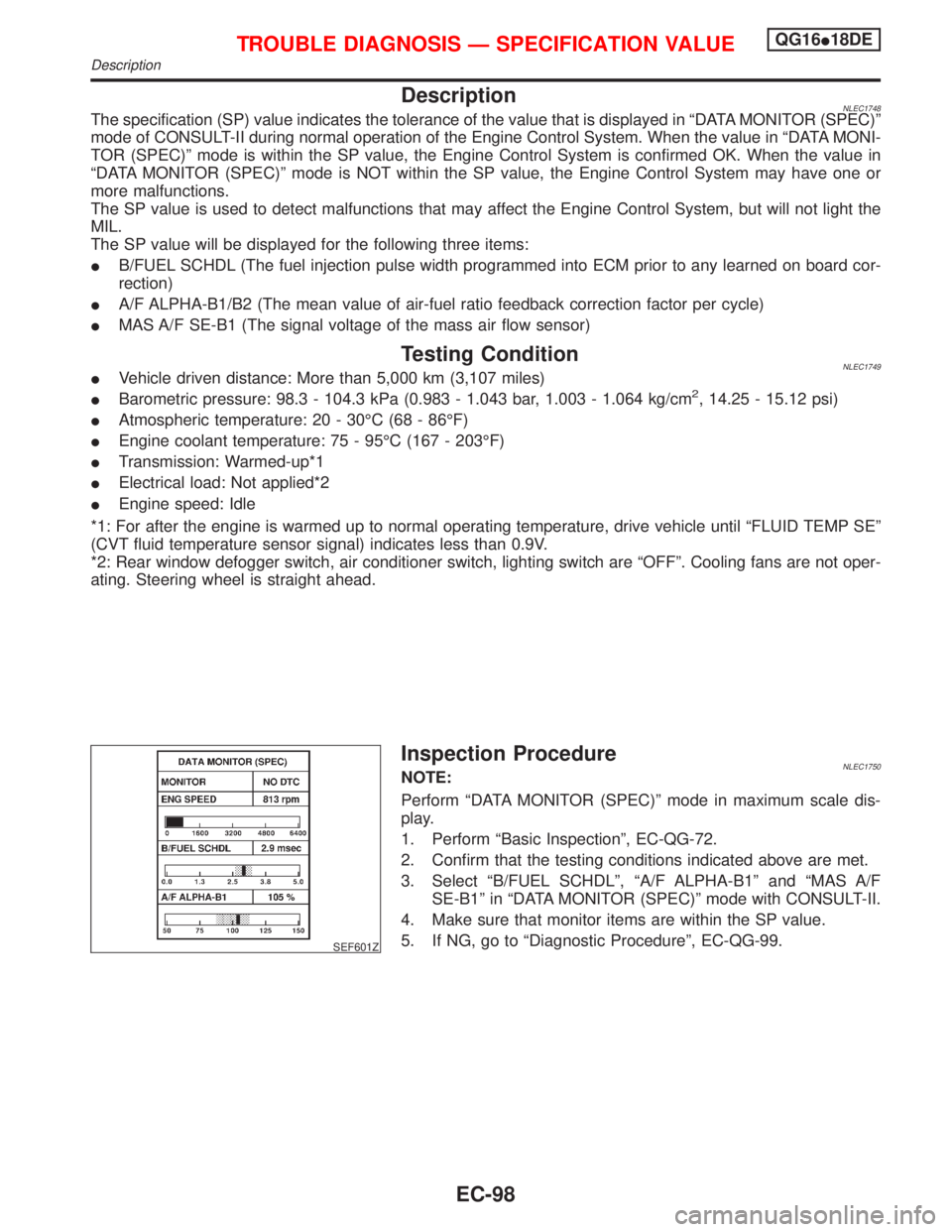
DescriptionNLEC1748The specification (SP) value indicates the tolerance of the value that is displayed in ªDATA MONITOR (SPEC)º
mode of CONSULT-II during normal operation of the Engine Control System. When the value in ªDATA MONI-
TOR (SPEC)º mode is within the SP value, the Engine Control System is confirmed OK. When the value in
ªDATA MONITOR (SPEC)º mode is NOT within the SP value, the Engine Control System may have one or
more malfunctions.
The SP value is used to detect malfunctions that may affect the Engine Control System, but will not light the
MIL.
The SP value will be displayed for the following three items:
IB/FUEL SCHDL (The fuel injection pulse width programmed into ECM prior to any learned on board cor-
rection)
IA/F ALPHA-B1/B2 (The mean value of air-fuel ratio feedback correction factor per cycle)
IMAS A/F SE-B1 (The signal voltage of the mass air flow sensor)
Testing ConditionNLEC1749IVehicle driven distance: More than 5,000 km (3,107 miles)
IBarometric pressure: 98.3 - 104.3 kPa (0.983 - 1.043 bar, 1.003 - 1.064 kg/cm2, 14.25 - 15.12 psi)
IAtmospheric temperature: 20 - 30ÉC (68 - 86ÉF)
IEngine coolant temperature: 75 - 95ÉC (167 - 203ÉF)
ITransmission: Warmed-up*1
IElectrical load: Not applied*2
IEngine speed: Idle
*1: For after the engine is warmed up to normal operating temperature, drive vehicle until ªFLUID TEMP SEº
(CVT fluid temperature sensor signal) indicates less than 0.9V.
*2: Rear window defogger switch, air conditioner switch, lighting switch are ªOFFº. Cooling fans are not oper-
ating. Steering wheel is straight ahead.
SEF601Z
Inspection ProcedureNLEC1750NOTE:
Perform ªDATA MONITOR (SPEC)º mode in maximum scale dis-
play.
1. Perform ªBasic Inspectionº, EC-QG-72.
2. Confirm that the testing conditions indicated above are met.
3. Select ªB/FUEL SCHDLº, ªA/F ALPHA-B1º and ªMAS A/F
SE-B1º in ªDATA MONITOR (SPEC)º mode with CONSULT-II.
4. Make sure that monitor items are within the SP value.
5. If NG, go to ªDiagnostic Procedureº, EC-QG-99.
TROUBLE DIAGNOSIS Ð SPECIFICATION VALUEQG16I18DE
Description
EC-98
Page 568 of 2267
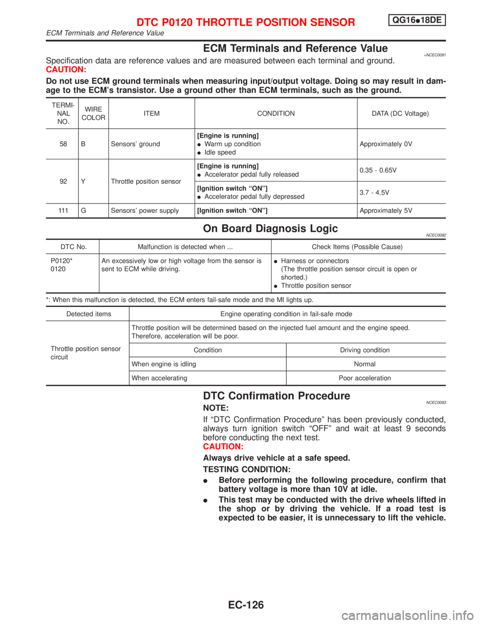
ECM Terminals and Reference Value=NCEC0081Specification data are reference values and are measured between each terminal and ground.
CAUTION:
Do not use ECM ground terminals when measuring input/output voltage. Doing so may result in dam-
age to the ECM's transistor. Use a ground other than ECM terminals, such as the ground.
TERMI-
NAL
NO.WIRE
COLORITEM CONDITION DATA (DC Voltage)
58 B Sensors' ground[Engine is running]
IWarm up condition
IIdle speedApproximately 0V
92 Y Throttle position sensor[Engine is running]
IAccelerator pedal fully released0.35 - 0.65V
[Ignition switch ªONº]
IAccelerator pedal fully depressed3.7 - 4.5V
111 G Sensors' power supply[Ignition switch ªONº]Approximately 5V
On Board Diagnosis LogicNCEC0082
DTC No. Malfunction is detected when ... Check Items (Possible Cause)
P0120*
0120An excessively low or high voltage from the sensor is
sent to ECM while driving.IHarness or connectors
(The throttle position sensor circuit is open or
shorted.)
IThrottle position sensor
*: When this malfunction is detected, the ECM enters fail-safe mode and the MI lights up.
Detected items Engine operating condition in fail-safe mode
Throttle position sensor
circuitThrottle position will be determined based on the injected fuel amount and the engine speed.
Therefore, acceleration will be poor.
Condition Driving condition
When engine is idling Normal
When accelerating Poor acceleration
DTC Confirmation ProcedureNCEC0083NOTE:
If ªDTC Confirmation Procedureº has been previously conducted,
always turn ignition switch ªOFFº and wait at least 9 seconds
before conducting the next test.
CAUTION:
Always drive vehicle at a safe speed.
TESTING CONDITION:
IBefore performing the following procedure, confirm that
battery voltage is more than 10V at idle.
IThis test may be conducted with the drive wheels lifted in
the shop or by driving the vehicle. If a road test is
expected to be easier, it is unnecessary to lift the vehicle.
DTC P0120 THROTTLE POSITION SENSORQG16I18DE
ECM Terminals and Reference Value
EC-126
Page 704 of 2267
DescriptionNCEC0248SYSTEM DESCRIPTIONNCEC0248S01
Sensor Input Signal to ECMECM func-
tionActuator
Crankshaft position sensor (POS) Engine speed
EVAP can-
ister purge
controlEVAP canister purge volume
control solenoid valve Mass air flow sensor Amount of intake air
Engine coolant temperature sensor Engine coolant temperature
Battery Battery voltage
Ignition switch Start signal
Throttle position sensor Throttle position
Heated oxygen 1 sensorDensity of oxygen in exhaust gas
(Mixture ratio feedback signal)
Vehicle speed sensor or ABS actuator and
electric unit (control unit)Vehicle speed
This system controls flow rate of fuel vapor from the EVAP canis-
ter. The opening of the vapor by-pass passage in the EVAP canis-
ter purge volume control solenoid valve changes to control the flow
rate. The EVAP canister purge volume control solenoid valve
repeats ON/OFF operation according to the signal sent from the
ECM. The opening of the valve varies for optimum engine control.
The optimum value stored in the ECM is determined by consider-
ing various engine conditions. When the engine is operating, the
flow rate of fuel vapor from the EVAP canister is regulated as the
air flow changes.
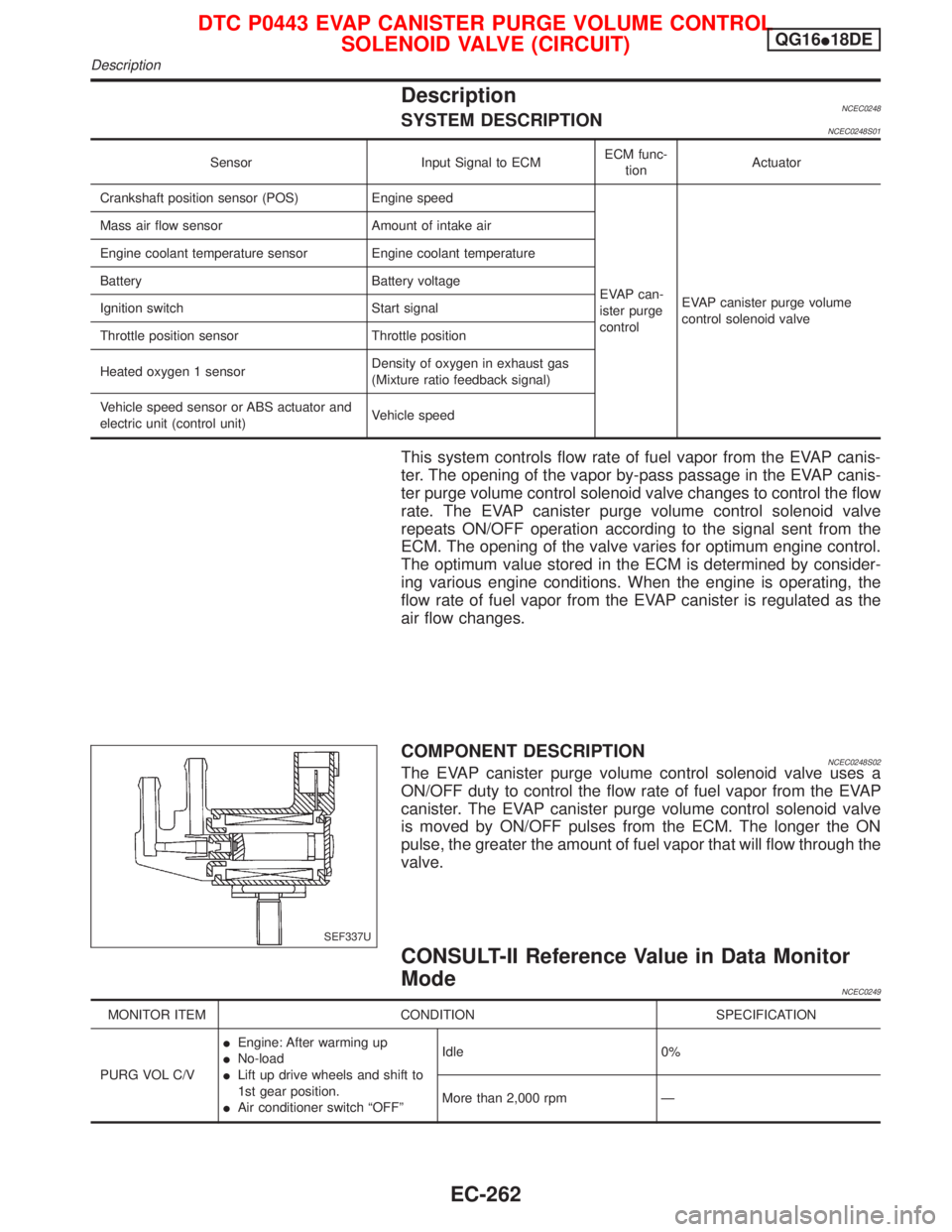
COMPONENT DESCRIPTIONNCEC0248S02The EVAP canister purge volume control solenoid valve uses a
ON/OFF duty to control the flow rate of fuel vapor from the EVAP
canister. The EVAP canister purge volume control solenoid valve
is moved by ON/OFF pulses from the ECM. The longer the ON
pulse, the greater the amount of fuel vapor that will flow through the
valve.
CONSULT-II Reference Value in Data Monitor
Mode
NCEC0249
MONITOR ITEM CONDITION SPECIFICATION
PURG VOL C/VIEngine: After warming up
INo-load
ILift up drive wheels and shift to
1st gear position.
IAir conditioner switch ªOFFºIdle 0%
More than 2,000 rpm Ð
SEF337U
DTC P0443 EVAP CANISTER PURGE VOLUME CONTROL
SOLENOID VALVE (CIRCUIT)QG16I18DE
Description
EC-262
Page 709 of 2267
Component DescriptionNCEC0272MODELS WITH VEHICLE SPEED SENSOR
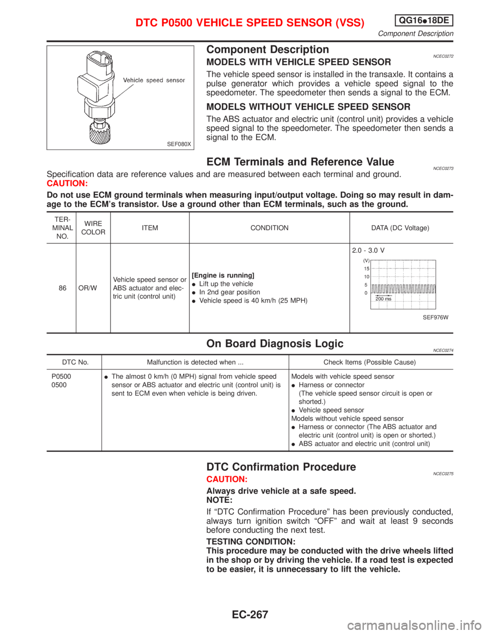
The vehicle speed sensor is installed in the transaxle. It contains a
pulse generator which provides a vehicle speed signal to the
speedometer. The speedometer then sends a signal to the ECM.
MODELS WITHOUT VEHICLE SPEED SENSOR
The ABS actuator and electric unit (control unit) provides a vehicle
speed signal to the speedometer. The speedometer then sends a
signal to the ECM.
ECM Terminals and Reference ValueNCEC0273Specification data are reference values and are measured between each terminal and ground.
CAUTION:
Do not use ECM ground terminals when measuring input/output voltage. Doing so may result in dam-
age to the ECM's transistor. Use a ground other than ECM terminals, such as the ground.
TER-
MINAL
NO.WIRE
COLORITEM CONDITION DATA (DC Voltage)
86 OR/WVehicle speed sensor or
ABS actuator and elec-
tric unit (control unit)[Engine is running]
ILift up the vehicle
IIn 2nd gear position
IVehicle speed is 40 km/h (25 MPH)2.0 - 3.0 V
SEF976W
On Board Diagnosis LogicNCEC0274
DTC No. Malfunction is detected when ... Check Items (Possible Cause)
P0500
0500IThe almost 0 km/h (0 MPH) signal from vehicle speed
sensor or ABS actuator and electric unit (control unit) is
sent to ECM even when vehicle is being driven.Models with vehicle speed sensor
IHarness or connector
(The vehicle speed sensor circuit is open or
shorted.)
IVehicle speed sensor
Models without vehicle speed sensor
IHarness or connector (The ABS actuator and
electric unit (control unit) is open or shorted.)
IABS actuator and electric unit (control unit)
DTC Confirmation ProcedureNCEC0275CAUTION:
Always drive vehicle at a safe speed.
NOTE:
If ªDTC Confirmation Procedureº has been previously conducted,
always turn ignition switch ªOFFº and wait at least 9 seconds
before conducting the next test.
TESTING CONDITION:
This procedure may be conducted with the drive wheels lifted
in the shop or by driving the vehicle. If a road test is expected
to be easier, it is unnecessary to lift the vehicle.
SEF080X
DTC P0500 VEHICLE SPEED SENSOR (VSS)QG16I18DE
Component Description
EC-267