1999 NISSAN PRIMERA wheel
[x] Cancel search: wheelPage 846 of 2267
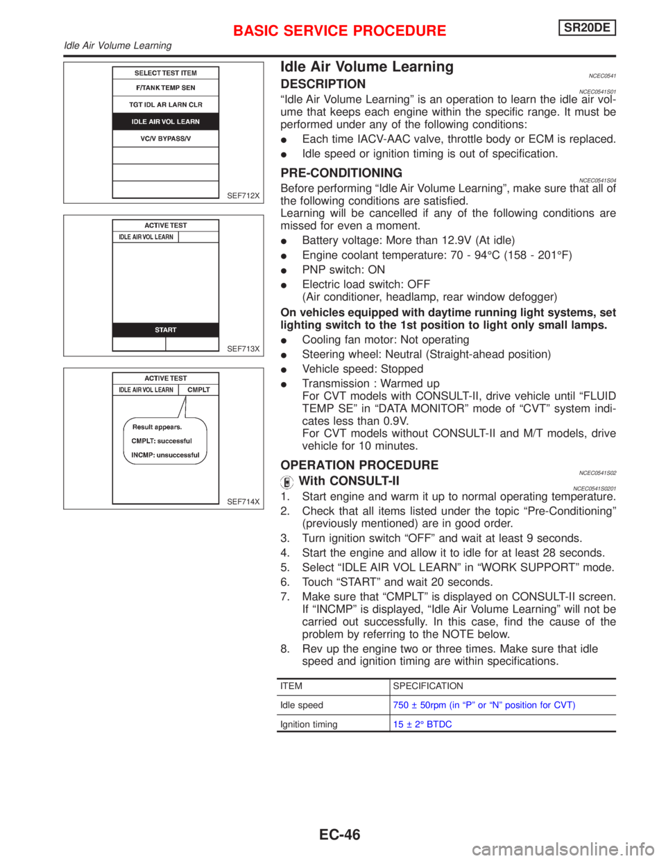
Idle Air Volume LearningNCEC0541DESCRIPTIONNCEC0541S01ªIdle Air Volume Learningº is an operation to learn the idle air vol-
ume that keeps each engine within the specific range. It must be
performed under any of the following conditions:
IEach time IACV-AAC valve, throttle body or ECM is replaced.
IIdle speed or ignition timing is out of specification.
PRE-CONDITIONINGNCEC0541S04Before performing ªIdle Air Volume Learningº, make sure that all of
the following conditions are satisfied.
Learning will be cancelled if any of the following conditions are
missed for even a moment.
IBattery voltage: More than 12.9V (At idle)
IEngine coolant temperature: 70 - 94ÉC (158 - 201ÉF)
IPNP switch: ON
IElectric load switch: OFF
(Air conditioner, headlamp, rear window defogger)
On vehicles equipped with daytime running light systems, set
lighting switch to the 1st position to light only small lamps.
ICooling fan motor: Not operating
ISteering wheel: Neutral (Straight-ahead position)
IVehicle speed: Stopped
ITransmission : Warmed up
For CVT models with CONSULT-II, drive vehicle until ªFLUID
TEMP SEº in ªDATA MONITORº mode of ªCVTº system indi-
cates less than 0.9V.
For CVT models without CONSULT-II and M/T models, drive
vehicle for 10 minutes.
OPERATION PROCEDURENCEC0541S02With CONSULT-IINCEC0541S02011. Start engine and warm it up to normal operating temperature.
2. Check that all items listed under the topic ªPre-Conditioningº
(previously mentioned) are in good order.
3. Turn ignition switch ªOFFº and wait at least 9 seconds.
4. Start the engine and allow it to idle for at least 28 seconds.
5. Select ªIDLE AIR VOL LEARNº in ªWORK SUPPORTº mode.
6. Touch ªSTARTº and wait 20 seconds.
7. Make sure that ªCMPLTº is displayed on CONSULT-II screen.
If ªINCMPº is displayed, ªIdle Air Volume Learningº will not be
carried out successfully. In this case, find the cause of the
problem by referring to the NOTE below.
8. Rev up the engine two or three times. Make sure that idle
speed and ignition timing are within specifications.
ITEM SPECIFICATION
Idle speed750 50rpm (in ªPº or ªNº position for CVT)
Ignition timing15 2É BTDC
SEF712X
SEF713X
SEF714X
BASIC SERVICE PROCEDURESR20DE
Idle Air Volume Learning
EC-46
Page 884 of 2267
Basic InspectionNCEC0038Precaution:
Perform Basic Inspection without electrical or mechanical loads applied;
IHeadlamp switch is OFF,
IOn vehicles equipped with daytime running light systems, set lighting switch to the 1st position to light only
small lamps.
IAir conditioner switch is OFF,
IRear window defogger switch is OFF,
ISteering wheel is in the straight-ahead position, etc.
1 INSPECTION START
1. Check service records for any recent repairs that may indicate a related problem, or the current need for scheduled maintenance.
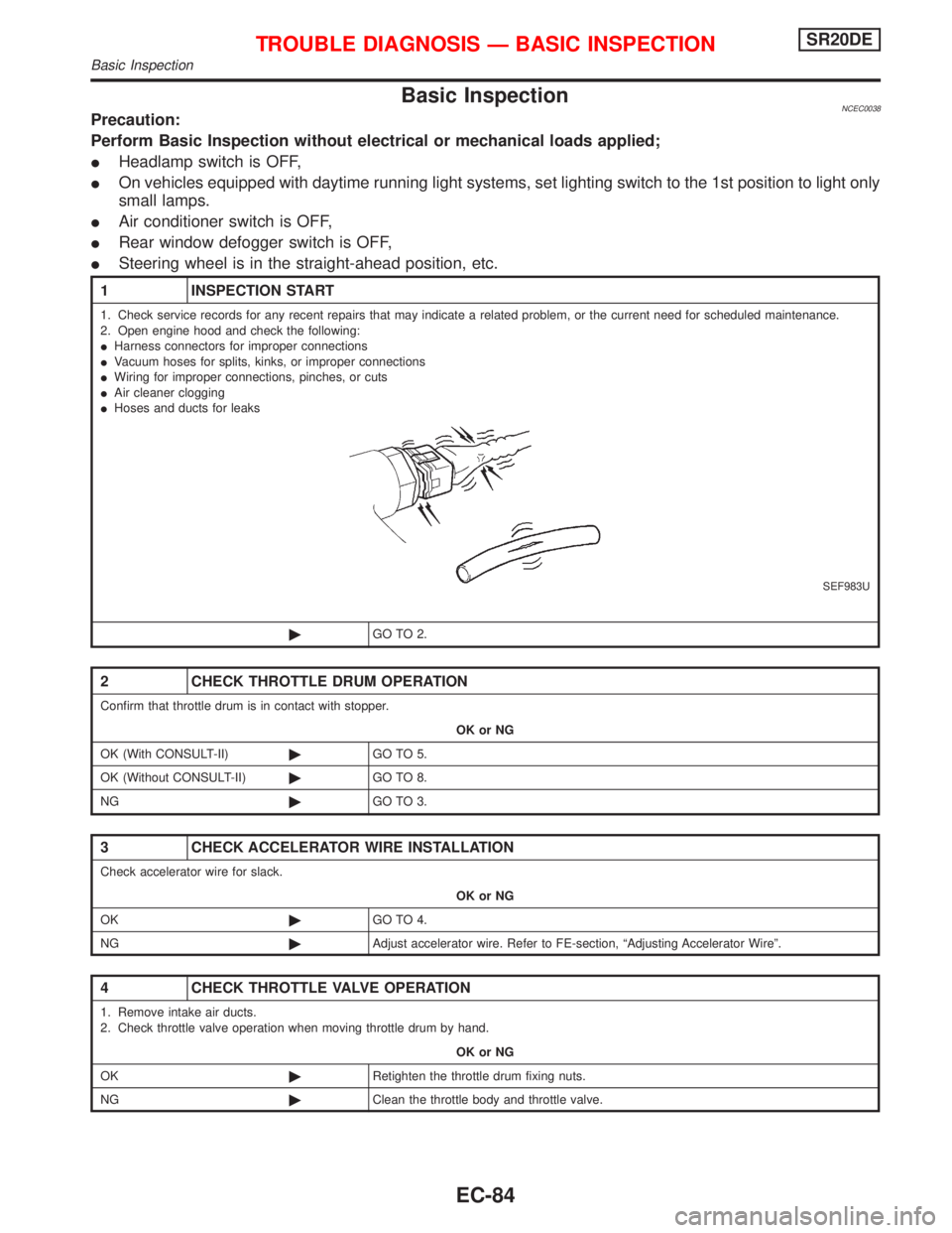
2. Open engine hood and check the following:
IHarness connectors for improper connections
IVacuum hoses for splits, kinks, or improper connections
IWiring for improper connections, pinches, or cuts
IAir cleaner clogging
IHoses and ducts for leaks
SEF983U
©GO TO 2.
2 CHECK THROTTLE DRUM OPERATION
Confirm that throttle drum is in contact with stopper.
OK or NG
OK (With CONSULT-II)©GO TO 5.
OK (Without CONSULT-II)©GO TO 8.
NG©GO TO 3.
3 CHECK ACCELERATOR WIRE INSTALLATION
Check accelerator wire for slack.
OK or NG
OK©GO TO 4.
NG©Adjust accelerator wire. Refer to FE-section, ªAdjusting Accelerator Wireº.
4 CHECK THROTTLE VALVE OPERATION
1. Remove intake air ducts.
2. Check throttle valve operation when moving throttle drum by hand.
OK or NG
OK©Retighten the throttle drum fixing nuts.
NG©Clean the throttle body and throttle valve.
TROUBLE DIAGNOSIS Ð BASIC INSPECTIONSR20DE
Basic Inspection
EC-84
Page 896 of 2267
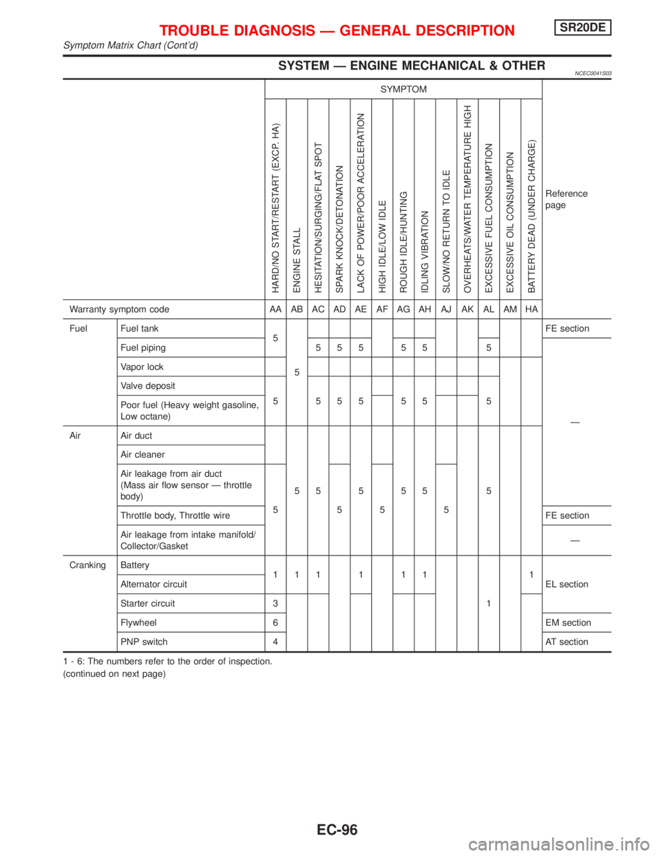
SYSTEM Ð ENGINE MECHANICAL & OTHERNCEC0041S03
SYMPTOM
Reference
page
HARD/NO START/RESTART (EXCP. HA)
ENGINE STALL
HESITATION/SURGING/FLAT SPOT
SPARK KNOCK/DETONATION
LACK OF POWER/POOR ACCELERATION
HIGH IDLE/LOW IDLE
ROUGH IDLE/HUNTING
IDLING VIBRATION
SLOW/NO RETURN TO IDLE
OVERHEATS/WATER TEMPERATURE HIGH
EXCESSIVE FUEL CONSUMPTION
EXCESSIVE OIL CONSUMPTION
BATTERY DEAD (UNDER CHARGE)
Warranty symptom code AA AB AC AD AE AF AG AH AJ AK AL AM HA
Fuel Fuel tank
5
5FE section
Fuel piping 5 5 5 5 5 5
Ð Vapor lock
Valve deposit
5 555 55 5
Poor fuel (Heavy weight gasoline,
Low octane)
Air Air duct
55555 5 Air cleaner
Air leakage from air duct
(Mass air flow sensor Ð throttle
body)
5555
Throttle body, Throttle wireFE section
Air leakage from intake manifold/
Collector/GasketÐ
Cranking Battery
111111
11
EL section Alternator circuit
Starter circuit 3
Flywheel 6 EM section
PNP switch 4 AT section
1 - 6: The numbers refer to the order of inspection.
(continued on next page)
TROUBLE DIAGNOSIS Ð GENERAL DESCRIPTIONSR20DE
Symptom Matrix Chart (Cont'd)
EC-96
Page 898 of 2267
CONSULT-II Reference Value in Data Monitor
Mode
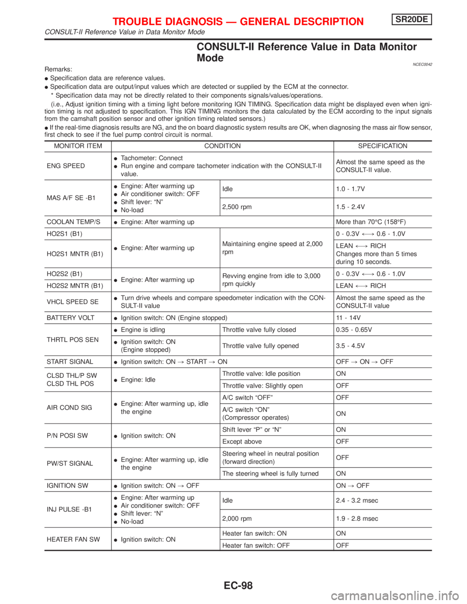
NCEC0042Remarks:
ISpecification data are reference values.
ISpecification data are output/input values which are detected or supplied by the ECM at the connector.
* Specification data may not be directly related to their components signals/values/operations.
(i.e., Adjust ignition timing with a timing light before monitoring IGN TIMING. Specification data might be displayed even when igni-
tion timing is not adjusted to specification. This IGN TIMING monitors the data calculated by the ECM according to the input signals
from the camshaft position sensor and other ignition timing related sensors.)
IIf the real-time diagnosis results are NG, and the on board diagnostic system results are OK, when diagnosing the mass air flow sensor,
first check to see if the fuel pump control circuit is normal.
MONITOR ITEM CONDITION SPECIFICATION
ENG SPEEDITachometer: Connect
IRun engine and compare tachometer indication with the CONSULT-II
value.Almost the same speed as the
CONSULT-II value.
MAS A/F SE -B1IEngine: After warming up
IAir conditioner switch: OFF
IShift lever: ªNº
INo-loadIdle 1.0 - 1.7V
2,500 rpm 1.5 - 2.4V
COOLAN TEMP/SIEngine: After warming up More than 70ÉC (158ÉF)
HO2S1 (B1)
IEngine: After warming upMaintaining engine speed at 2,000
rpm0 - 0.3V+,0.6 - 1.0V
HO2S1 MNTR (B1)LEAN+,RICH
Changes more than 5 times
during 10 seconds.
HO2S2 (B1)
IEngine: After warming upRevving engine from idle to 3,000
rpm quickly0 - 0.3V+,0.6 - 1.0V
HO2S2 MNTR (B1)LEAN+,RICH
VHCL SPEED SEITurn drive wheels and compare speedometer indication with the CON-
SULT-II valueAlmost the same speed as the
CONSULT-II value
BATTERY VOLTIIgnition switch: ON (Engine stopped) 11 - 14V
THRTL POS SENIEngine is idling Throttle valve fully closed 0.35 - 0.65V
IIgnition switch: ON
(Engine stopped)Throttle valve fully opened 3.5 - 4.5V
START SIGNALIIgnition switch: ON,START,ON OFF,ON,OFF
CLSD THL/P SW
CLSD THL POSIEngine: IdleThrottle valve: Idle position ON
Throttle valve: Slightly open OFF
AIR COND SIGIEngine: After warming up, idle
the engineA/C switch ªOFFº OFF
A/C switch ªONº
(Compressor operates)ON
P/N POSI SWIIgnition switch: ONShift lever ªPº or ªNº ON
Except above OFF
PW/ST SIGNALIEngine: After warming up, idle
the engineSteering wheel in neutral position
(forward direction)OFF
The steering wheel is fully turned ON
IGNITION SWIIgnition switch: ON,OFF ON,OFF
INJ PULSE -B1IEngine: After warming up
IAir conditioner switch: OFF
IShift lever: ªNº
INo-loadIdle 2.4 - 3.2 msec
2,000 rpm 1.9 - 2.8 msec
HEATER FAN SWIIgnition switch: ONHeater fan switch: ON ON
Heater fan switch: OFF OFF
TROUBLE DIAGNOSIS Ð GENERAL DESCRIPTIONSR20DE
CONSULT-II Reference Value in Data Monitor Mode
EC-98
Page 906 of 2267
![NISSAN PRIMERA 1999 Electronic Repair Manual TERMI-
NAL
NO.WIRE
COLORITEM CONDITION DATA (DC Voltage)
36*1 G Ignition check[Engine is running]
IWarm-up condition
IIdle speedApproximately 13V
SEF998V
[Engine is running]
IEngine speed is 2,000 rpm NISSAN PRIMERA 1999 Electronic Repair Manual TERMI-
NAL
NO.WIRE
COLORITEM CONDITION DATA (DC Voltage)
36*1 G Ignition check[Engine is running]
IWarm-up condition
IIdle speedApproximately 13V
SEF998V
[Engine is running]
IEngine speed is 2,000 rpm](/manual-img/5/57377/w960_57377-905.png)
TERMI-
NAL
NO.WIRE
COLORITEM CONDITION DATA (DC Voltage)
36*1 G Ignition check[Engine is running]
IWarm-up condition
IIdle speedApproximately 13V
SEF998V
[Engine is running]
IEngine speed is 2,000 rpmApproximately 12V
SEF999V
40 YThrottle position switch
(Closed position)[Engine is running]
IAccelerator pedal releasedBATTERY VOLTAGE
(11 - 14V)
[Ignition switch ªONº]
IAccelerator pedal depressedApproximately 0V
41 B/Y Start signal[Ignition switch ªONº]Approximately 0V
[Ignition switch ªSTARTº]9 - 12V
42 G/OR PNP switch[Ignition switch ªONº]
IGear position is ªNeutral positionº (M/T mod-
els)
IGear position is ªPº or ªNº (CVT models)Approximately 0V
[Ignition switch ªONº]
IExcept the above gear positionBATTERY VOLTAGE
(11 - 14V)
43 B/R Ignition switch[Ignition switch ªOFFº]0V
[Ignition switch ªONº]BATTERY VOLTAGE
(11 - 14V)
44 Ð Air conditioner switch[Engine is running]
IBoth air conditioner switch and blower switch
are ªONº (Compressor operates)Approximately 0V
[Engine is running]
IAir conditioner switch is ªOFFºApproximately 5V
46 PU/WPower steering oil pres-
sure switch[Engine is running]
ISteering wheel is fully turnedApproximately 0V
[Engine is running]
ISteering wheel is not turnedApproximately 5V
48 B ECM ground[Engine is running]
IIdle speedEngine ground
(Probe this terminal with (þ)
tester probe when measuring)
50 R Electric load signal[Engine is running]
IHeadlamp switch or rear window defogger
switch is ªONºBATTERY VOLTAGE
(11 - 14V)
*1: If so equipped
TROUBLE DIAGNOSIS Ð GENERAL DESCRIPTIONSR20DE
ECM Terminals and Reference Value (Cont'd)
EC-106
Page 910 of 2267
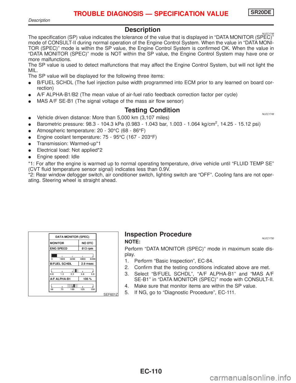
DescriptionNLEC1748The specification (SP) value indicates the tolerance of the value that is displayed in ªDATA MONITOR (SPEC)º
mode of CONSULT-II during normal operation of the Engine Control System. When the value in ªDATA MONI-
TOR (SPEC)º mode is within the SP value, the Engine Control System is confirmed OK. When the value in
ªDATA MONITOR (SPEC)º mode is NOT within the SP value, the Engine Control System may have one or
more malfunctions.
The SP value is used to detect malfunctions that may affect the Engine Control System, but will not light the
MIL.
The SP value will be displayed for the following three items:
IB/FUEL SCHDL (The fuel injection pulse width programmed into ECM prior to any learned on board cor-
rection)
IA/F ALPHA-B1/B2 (The mean value of air-fuel ratio feedback correction factor per cycle)
IMAS A/F SE-B1 (The signal voltage of the mass air flow sensor)
Testing ConditionNLEC1749IVehicle driven distance: More than 5,000 km (3,107 miles)
IBarometric pressure: 98.3 - 104.3 kPa (0.983 - 1.043 bar, 1.003 - 1.064 kg/cm2, 14.25 - 15.12 psi)
IAtmospheric temperature: 20 - 30ÉC (68 - 86ÉF)
IEngine coolant temperature: 75 - 95ÉC (167 - 203ÉF)
ITransmission: Warmed-up*1
IElectrical load: Not applied*2
IEngine speed: Idle
*1: For after the engine is warmed up to normal operating temperature, drive vehicle until ªFLUID TEMP SEº
(CVT fluid temperature sensor signal) indicates less than 0.9V.
*2: Rear window defogger switch, air conditioner switch, lighting switch are ªOFFº. Cooling fans are not oper-
ating. Steering wheel is straight ahead.
SEF601Z
Inspection ProcedureNLEC1750NOTE:
Perform ªDATA MONITOR (SPEC)º mode in maximum scale dis-
play.
1. Perform ªBasic Inspectionº, EC-84.
2. Confirm that the testing conditions indicated above are met.
3. Select ªB/FUEL SCHDLº, ªA/F ALPHA-B1º and ªMAS A/F
SE-B1º in ªDATA MONITOR (SPEC)º mode with CONSULT-II.
4. Make sure that monitor items are within the SP value.
5. If NG, go to ªDiagnostic Procedureº, EC-111.
TROUBLE DIAGNOSIS Ð SPECIFICATION VALUESR20DE
Description
EC-110
Page 938 of 2267
ECM Terminals and Reference Value=NCEC0081Specification data are reference values and are measured between each terminal and 48 (ECM ground).
TERMI-
NAL
NO.WIRE
COLORITEM CONDITION DATA (DC Voltage)
58 B Sensors' ground[Engine is running]
IWarm up condition
IIdle speedApproximately 0V
92 Y Throttle position sensor[Engine is running]
IAccelerator pedal fully released0.35 - 0.65V
[Ignition switch ªONº]
IAccelerator pedal fully depressedApproximately 4.0V
111 G Sensors' power supply[Ignition switch ªONº]Approximately 5V
On Board Diagnosis LogicNCEC0082
DTC No. Malfunction is detected when ... Check Items (Possible Cause)
P0120
0120An excessively low or high voltage from the sensor is
sent to ECM while driving*.IHarness or connectors
(The throttle position sensor circuit is open or
shorted.)
IThrottle position sensor
*: When this malfunction is detected, the ECM enters fail-safe mode and the MI lights up.
Detected items Engine operating condition in fail-safe mode
Throttle position sensor
circuitThrottle position will be determined based on the injected fuel amount and the engine speed.
Therefore, acceleration will be poor.
Condition Driving condition
When engine is idling Normal
When accelerating Poor acceleration
DTC Confirmation ProcedureNCEC0083NOTE:
If ªDTC Confirmation Procedureº has been previously conducted,
always turn ignition switch ªOFFº and wait at least 9 seconds
before conducting the next test.
CAUTION:
Always drive vehicle at a safe speed.
TESTING CONDITION:
IBefore performing the following procedure, confirm that
battery voltage is more than 10V at idle.
IThis test may be conducted with the drive wheels lifted in
the shop or by driving the vehicle. If a road test is
expected to be easier, it is unnecessary to lift the vehicle.
DTC P0120 THROTTLE POSITION SENSORSR20DE
ECM Terminals and Reference Value
EC-138
Page 1024 of 2267
On Board Diagnosis LogicNCEC0202If a misfire occurs, the engine speed will fluctuate. If the fluctuation is detected by the crankshaft position sen-
sor (OBD), the misfire is diagnosed.
Sensor Input Signal to ECM ECM function
Crankshaft position sensor (OBD) Engine speed On board diagnosis of misfire
The misfire detection logic consists of the following two conditions.
1. One Trip Detection Logic (Three Way Catalyst Damage)
On the first trip that a misfire condition occurs that can damage the three way catalyst (TWC) due to
overheating, the MI will blink.
When a misfire condition occurs, the ECM monitors the CKP sensor signal every 200 engine revolutions
for a change.
When the misfire condition decreases to a level that will not damage the TWC, the MI will turn off.
If another misfire condition occurs that can damage the TWC on a second trip, the MI will blink.
When the misfire condition decreases to a level that will not damage the TWC, the MI will remain on.
If another misfire condition occurs that can damage the TWC, the MI will begin to blink again.
2. Two Trip Detection Logic (Exhaust quality deterioration)
For misfire conditions that will not damage the TWC (but will affect exhaust vehicle emissions), the MI will
only light when the misfire is detected on a second trip. During this condition, the ECM monitors the CKP
sensor signal every 1,000 engine revolutions.
A misfire malfunction can be detected on any one cylinder or on multiple cylinders.
DTC No. Malfunction is detected when ... Check Items (Possible Cause)
P0300
0300IMultiple cylinders misfire.IImproper spark plug
IInsufficient compression
IIncorrect fuel pressure
IThe injector circuit is open or shorted
IInjectors
IIntake air leak
IThe ignition secondary circuit is open or
shorted
ILack of fuel
IHeated oxygen sensor 1 (front)
IDrive plate/Flywheel
IIncorrect distributor rotor P0301
0301INo. 1 cylinder misfires.
P0302
0302INo. 2 cylinder misfires.
P0303
0303INo. 3 cylinder misfires.
P0304
0304INo. 4 cylinder misfires.
DTC Confirmation ProcedureNCEC0203CAUTION:
Always drive vehicle at a safe speed.
NOTE:
If ªDTC Confirmation Procedureº has been previously conducted,
always turn ignition switch ªOFFº and wait at least 9 seconds
before conducting the next test.
TESTING CONDITION:
IAlways perform at a temperature above þ10ÉC (14ÉF).
With CONSULT-II
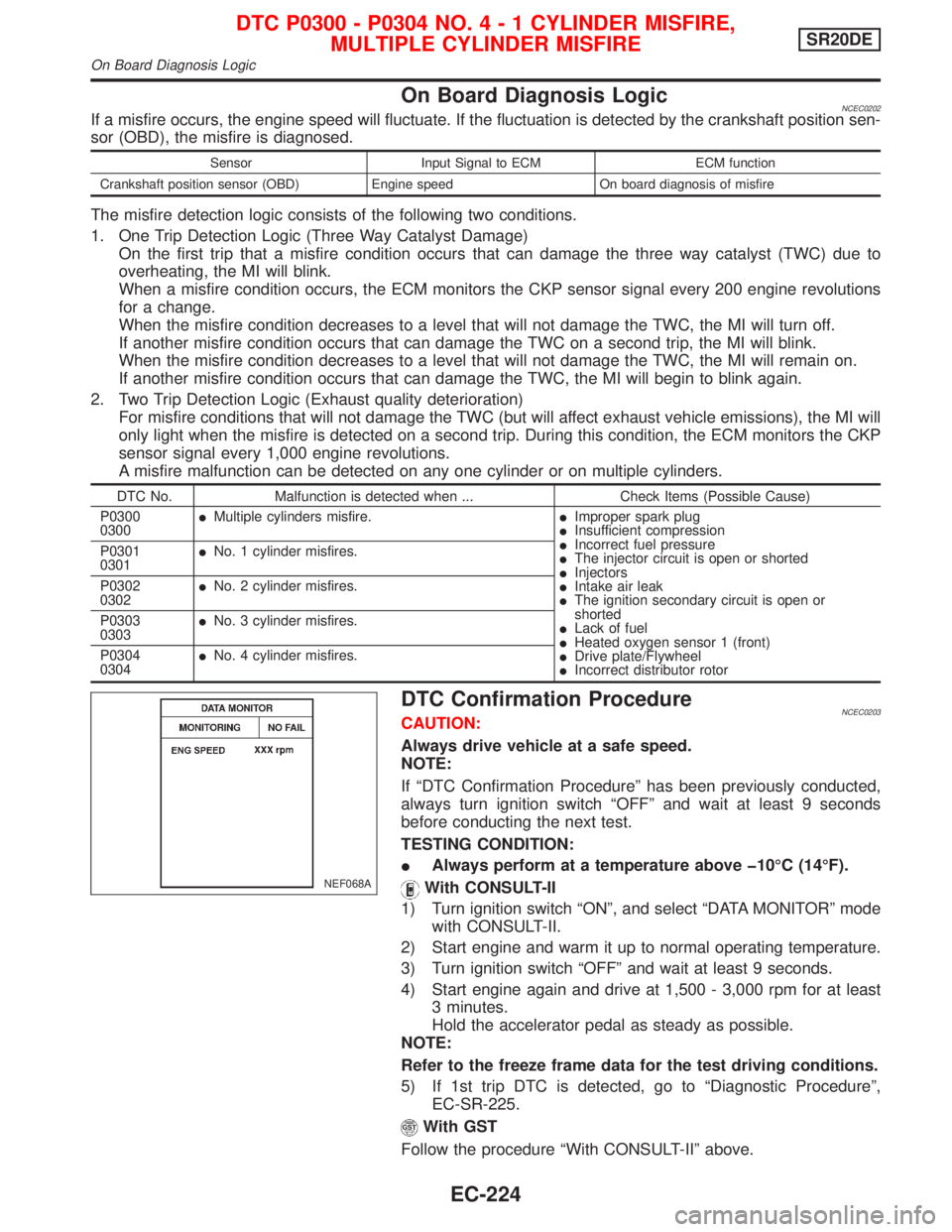
1) Turn ignition switch ªONº, and select ªDATA MONITORº mode
with CONSULT-II.
2) Start engine and warm it up to normal operating temperature.
3) Turn ignition switch ªOFFº and wait at least 9 seconds.
4) Start engine again and drive at 1,500 - 3,000 rpm for at least
3 minutes.
Hold the accelerator pedal as steady as possible.
NOTE:
Refer to the freeze frame data for the test driving conditions.
5) If 1st trip DTC is detected, go to ªDiagnostic Procedureº,
EC-SR-225.
With GST
Follow the procedure ªWith CONSULT-IIº above.
NEF068A
DTC P0300 - P0304 NO.4-1CYLINDER MISFIRE,
MULTIPLE CYLINDER MISFIRESR20DE
On Board Diagnosis Logic
EC-224