Page 1124 of 2267

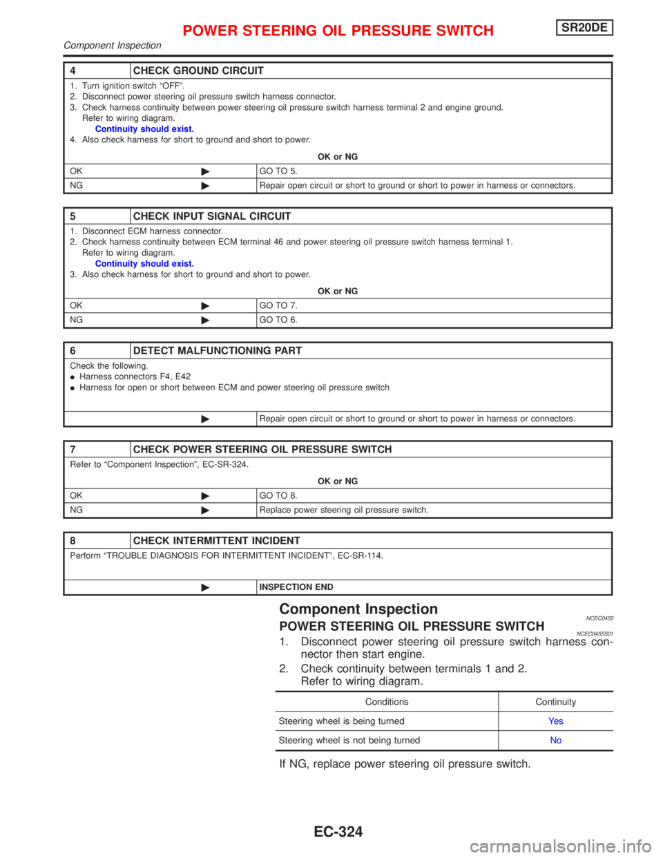
Component InspectionNCEC0455POWER STEERING OIL PRESSURE SWITCHNCEC0455S011. Disconnect power steering oil pressure switch harness con-
nector then start engine.
2. Check continuity between terminals 1 and 2.
Refer to wiring diagram.
Conditions Continuity
Steering wheel is being turnedYe s
Steering wheel is not being turnedNo
If NG, replace power steering oil pressure switch.
4 CHECK GROUND CIRCUIT
1. Turn ignition switch ªOFFº.
2. Disconnect power steering oil pressure switch harness connector.
3. Check harness continuity between power steering oil pressure switch harness terminal 2 and engine ground.
Refer to wiring diagram.
Continuity should exist.
4. Also check harness for short to ground and short to power.
OK or NG
OK©GO TO 5.
NG©Repair open circuit or short to ground or short to power in harness or connectors.
5 CHECK INPUT SIGNAL CIRCUIT
1. Disconnect ECM harness connector.
2. Check harness continuity between ECM terminal 46 and power steering oil pressure switch harness terminal 1.
Refer to wiring diagram.
Continuity should exist.
3. Also check harness for short to ground and short to power.
OK or NG
OK©GO TO 7.
NG©GO TO 6.
6 DETECT MALFUNCTIONING PART
Check the following.
IHarness connectors F4, E42
IHarness for open or short between ECM and power steering oil pressure switch
©Repair open circuit or short to ground or short to power in harness or connectors.
7 CHECK POWER STEERING OIL PRESSURE SWITCH
Refer to ªComponent Inspectionº, EC-SR-324.
OK or NG
OK©GO TO 8.
NG©Replace power steering oil pressure switch.
8 CHECK INTERMITTENT INCIDENT
Perform ªTROUBLE DIAGNOSIS FOR INTERMITTENT INCIDENTº, EC-SR-114.
©INSPECTION END
POWER STEERING OIL PRESSURE SWITCHSR20DE
Component Inspection
EC-324
Page 1130 of 2267

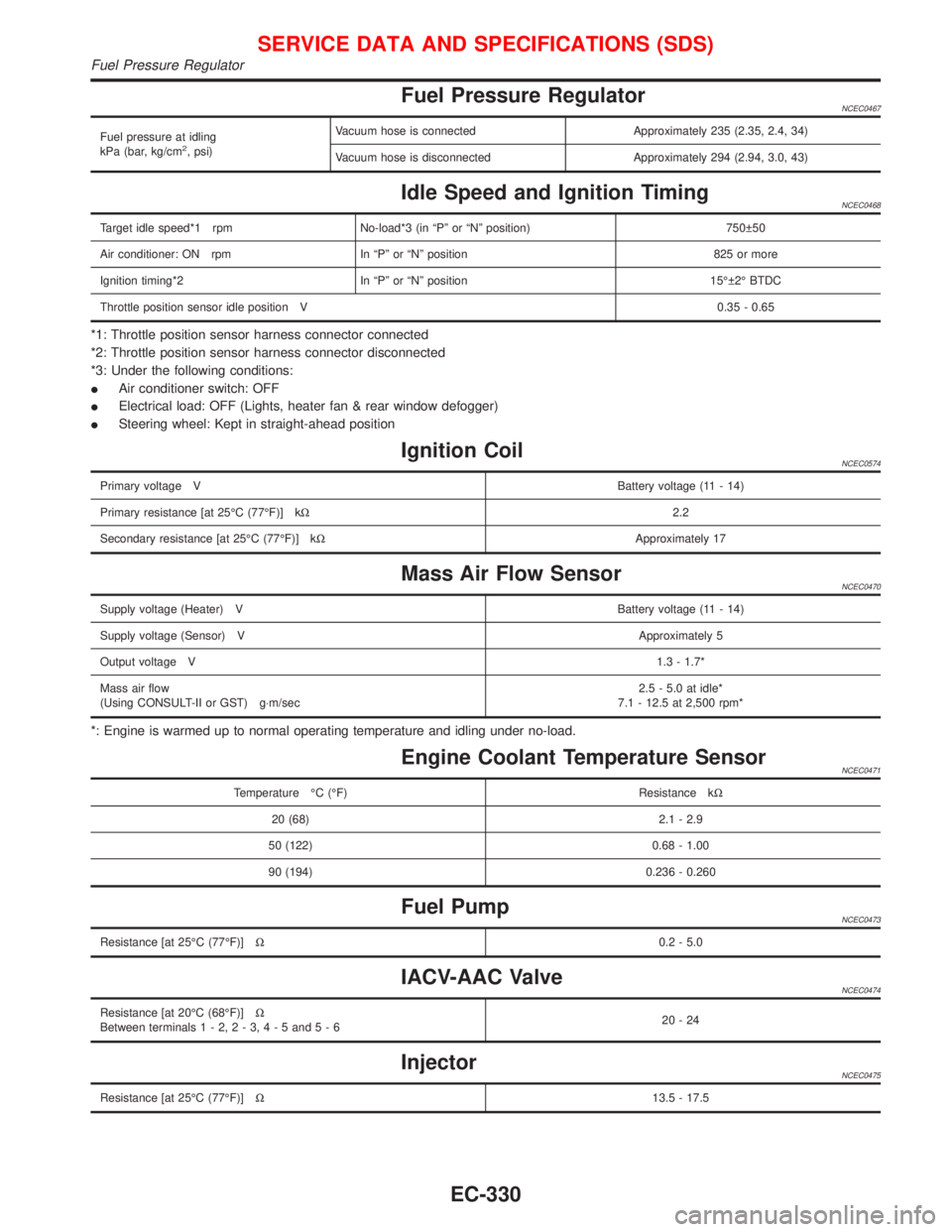
Fuel Pressure RegulatorNCEC0467
Fuel pressure at idling
kPa (bar, kg/cm2, psi)Vacuum hose is connected Approximately 235 (2.35, 2.4, 34)
Vacuum hose is disconnected Approximately 294 (2.94, 3.0, 43)
Idle Speed and Ignition TimingNCEC0468
Target idle speed*1 rpm No-load*3 (in ªPº or ªNº position) 750 50
Air conditioner: ON rpm In ªPº or ªNº position 825 or more
Ignition timing*2 In ªPº or ªNº position 15É 2É BTDC
Throttle position sensor idle position V0.35 - 0.65
*1: Throttle position sensor harness connector connected
*2: Throttle position sensor harness connector disconnected
*3: Under the following conditions:
IAir conditioner switch: OFF
IElectrical load: OFF (Lights, heater fan & rear window defogger)
ISteering wheel: Kept in straight-ahead position
Ignition CoilNCEC0574
Primary voltage VBattery voltage (11 - 14)
Primary resistance [at 25ÉC (77ÉF)] kW2.2
Secondary resistance [at 25ÉC (77ÉF)] kWApproximately 17
Mass Air Flow SensorNCEC0470
Supply voltage (Heater) VBattery voltage (11 - 14)
Supply voltage (Sensor) VApproximately 5
Output voltage V1.3 - 1.7*
Mass air flow
(Using CONSULT-II or GST) g×m/sec2.5 - 5.0 at idle*
7.1 - 12.5 at 2,500 rpm*
*: Engine is warmed up to normal operating temperature and idling under no-load.
Engine Coolant Temperature SensorNCEC0471
Temperature ÉC (ÉF) Resistance kW
20 (68) 2.1 - 2.9
50 (122) 0.68 - 1.00
90 (194) 0.236 - 0.260
Fuel PumpNCEC0473
Resistance [at 25ÉC (77ÉF)]W0.2 - 5.0
IACV-AAC ValveNCEC0474
Resistance [at 20ÉC (68ÉF)]W
Between terminals1-2,2-3,4-5and5-620-24
InjectorNCEC0475
Resistance [at 25ÉC (77ÉF)]W13.5 - 17.5
SERVICE DATA AND SPECIFICATIONS (SDS)
Fuel Pressure Regulator
EC-330
Page 1137 of 2267

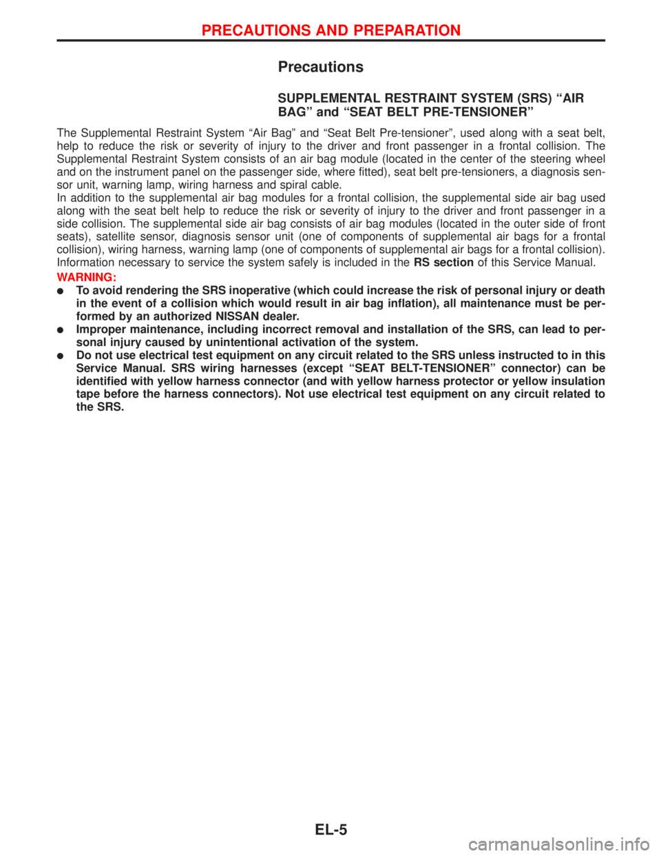
Precautions
SUPPLEMENTAL RESTRAINT SYSTEM (SRS)“AIR
BAG”and“SEAT BELT PRE-TENSIONER”
The Supplemental Restraint System “Air Bag” and “Seat Belt Pre-tensioner”, used along with a seat belt,
help to reduce the risk or severity of injury to the driver and front passenger in a frontal collision. The
Supplemental Restraint System consists of an air bag module (located in the center of the steering wheel
and on the instrument panel on the passenger side, where fitted), seat belt pre-tensioners, a diagnosis sen-
sor unit, warning lamp, wiring harness and spiral cable.
In addition to the supplemental air bag modules for a frontal collision, the supplemental side air bag used
along with the seat belt help to reduce the risk or severity of injury to the driver and front passenger in a
side collision. The supplemental side air bag consists of air bag modules (located in the outer side of front
seats), satellite sensor, diagnosis sensor unit (one of components of supplemental air bags for a frontal
collision), wiring harness, warning lamp (one of components of supplemental air bags for a frontal collision).
Information necessary to service the system safely is included in theRS sectionof this Service Manual.
WARNING:
�To avoid rendering the SRS inoperative (which could increase the risk of personal injury or death
in the event of a collision which would result in air bag inflation), all maintenance must be per-
formed by an authorized NISSAN dealer.
�Improper maintenance, including incorrect removal and installation of the SRS, can lead to per-
sonal injury caused by unintentional activation of the system.
�Do not use electrical test equipment on any circuit related to the SRS unless instructed to in this
Service Manual. SRS wiring harnesses (except“SEAT BELT-TENSIONER”connector) can be
identified with yellow harness connector (and with yellow harness protector or yellow insulation
tape before the harness connectors). Not use electrical test equipment on any circuit related to
the SRS.
PRECAUTIONS AND PREPARATION
EL-5
Page 1198 of 2267
Replacement
For removal and installation of spiral cable, refer to RS sec-
tion [“Installation—Air Bag Module and Spiral Cable”,
“SUPPLEMENTAL RESTRAINT SYSTEM (SRS)”].
�Each switch can be replaced without removing combination
switch base.
�To remove combination switch base, remove base attaching
screw.
�Before installing the steering wheel, align the steering wheel
guide pins with the screws which secure the combination
switch as shown in the left figure.
YEL903 Wiper and washer switch
Lighting switch Switch base
YEL904
SEL151V Combination
switchScrew
Steering wheel
guide pin
STEERING SWITCH
EL-66
Page 1231 of 2267
Removal and Installation
Front sensor
YEL621B
4.0 - 5.0 (0.4 - 0.51, 35 - 44)
Front linkage to be clamped onto
stabilizer bar with wheels down
and suspension settled. Rotation
to be fixed with link arm in hori-
zontal plane.
18 mm (0.71 in)
3.3 - 7.7 (0.33 - 0.79, 29 - 68)
Rear sensor
3.3 - 7.7 (0.33 - 0.79, 29 - 68)
:N·m (kg-m, in-lb)3.3 - 7.7 (0.33 - 0.79, 29 - 68)The rear sensor linkage does not
require setting, but with the wheel on
the ground and the suspension
settled, ensure that the link arm in the
same plane as the connector wire.
HEADLAMP—Headlamp Aiming Control (Auto)—
EL-99
Page 1293 of 2267
INSPECTION/VEHICLE SPEED SENSOR
(MT models with ABS)
CHECK VEHICLE SPEED SENSOR
OUTPUT.
1) Jack up the front wheels.
2) Turn ignition switch“ON”.
3) Check voltage between combination
meter terminals
�3and�1while
turning front wheels.
OK
�NG
Vehicle speed sensor is
OK.
Check continuity between speedometer
harness connector terminal
�31and
ABS actuator and electric unit connec-
tor terminal
�6.
Continuity should exist.
OK
�NG
Repair harness and con-
nector.
Replace vehicle speed sensor.YEL010D
YEL012D
�
�
METER AND GAUGES
Trouble Diagnoses (Models after VIN -
P11U0548750) (Cont’d)
EL-161
Page 1335 of 2267
Wiring Diagram—HORN—
Type-1
YEL180C
BATTERY
Refer to EL-POWER.: With gasoline engine
: With diesel engine
: With steering wheel switch
: Without steering wheel switch
HORN
RELAY
HORN
LOWHORN
HIGH
OFFON HORN
SWITCHHORN
SWITCH
REFER TO THE FOLLOWING
FUSE BLOCK - Junction Box (J/B)
FUSE BLOCK - Junction Box (J/B)
*: This connector is not shown in“HARNESS LAYOUT”of EL section.OFFONFUSE
BLOCK
(J/B)
SPIRAL
CABLE
HORN, CIGARETTE LIGHTER AND CLOCK
EL-203
Page 1350 of 2267
Schematic
YEL184C
IGNITION SWITCH
ACC or ONBATTERY
FUSE
FUSEFUSE COMBINATION
SWITCH (LIGHT-
ING SWITCH): RHD models
: With steering wheel switch
: With daytime light system
: Without daytime light system
: With CD auto changer
CD AUTO
CHANGER
AUDIO
TWEETER
LHFRONT
SPEAKER
RHTWEETER
RHREAR
SPEAKER
LHREAR
SPEAKER
RHDONGLE
CONTROL
UNIT
.DAYTIME
LIGHT
CONTROL
UNITDT
SOURCE
SWITCH
SPIRAL
CABLE
FRONT
SPEAKER
LHCOMBINATION
METER
(SPEEDOMETER)
ROOF
ANTENNA
AUDIO STEERING
WHEEL SWITCH SEEK
UP
SWITCH
VOLUME
SWITCH
SEEK
DOWN
SWITCH
SPECIAL
SWITCH
NATS
IMMU
AUDIO
EL-218