Page 1625 of 2267
IInstall new oil seal in the direction shown.
3. Apply engine oil to new oil seal and install it using a suitable
tool.
REAR OIL SEAL
1. Remove transaxle. (Refer to MT or AT section.)
2. Remove flywheel or drive plate.
3. Remove rear oil seal.
IBe careful not to scratch rear oil seal retainer.
IInstall new oil seal in the direction shown.
4. Apply engine oil to new oil seal and install it using a suitable
tool.
SEM715A Engine
outside
Dust seal lip Engine
inside
Oil seal lip
SEM998C
SEM999C
SEM715A Engine
inside
Oil seal lipEngine
outside
Dust seal lip
SEM001D Suitable tool
OIL SEAL REPLACEMENTSR20DE
EM-85
Page 1627 of 2267
RemovalNLEM01311. Release fuel pressure.
Refer to EC-SR-31, ªFuel Pressure Releaseº.
2. Remove engine under covers.
3. Remove front RH wheel and engine side cover.
4. Drain coolant by removing cylinder block drain plug and radia-
tor drain cock. Refer to MA-29, ªChanging Engine Coolantº.
5. Remove radiator.
6. Remove air duct to intake manifold.
7. Disconnect the following parts:
IVacuum hoses
IFuel hoses
IWires
IHarness
IConnectors
IFront exhaust tube
8. Remove all spark plugs.
9. Remove rocker cover bolts in numerical order.
10. Remove rocker cover.
11. Remove intake manifold supports.
12. Remove water pipe assembly.
SEM029G Engine
front
Loosen in numerical order.Rocker cover
SEM030G Intake manifold
supports
SEM065GIntake
manifold
CYLINDER HEADSR20DE
Removal
EM-87
Page 1645 of 2267
17. Install rocker cover and oil separator.
IBe sure to install washers between bolts and rocker cover.
ITightening procedure
STEP 1: Tighten bolts1-10-11-13-8inthat order.
STEP 2: Tighten bolts1-13inthat order.
:8-10N×m (0.8 - 1.0 kg-m, 69 - 87 in-lb)
18. Install the following parts:
ISpark plugs and leads
IRadiator
Refit hoses and refill with coolant.
Refer to MA-29, ªChanging Engine Coolantº.
IFront RH wheel
IEngine undercovers
19. Connect the following:
IVacuum hoses
IFuel hoses
IWire harnesses and connectors
IAir duct to intake manifold
IFront exhaust tube
SEM052G Engine
front
Tighten in numerical order.Rocker cover
CYLINDER HEADSR20DE
Installation (Cont'd)
EM-105
Page 1647 of 2267

WARNING:
IPosition vehicle on a flat and solid surface.
IPlace chocks at front and back of rear wheels.
IDo not remove engine until exhaust system has com-
pletely cooled;
Otherwise, you may burn yourself and/or fire may break
out in fuel line.
IBefore disconnecting fuel hose, release fuel pressure
from fuel line.
Refer to ªReleasing Fuel Pressureº in EC section.
IBe sure to hoist engine and transaxle in a safe manner.
IFor engines not equipped with engine slingers, attach
slingers and bolts described in PARTS CATALOG.
CAUTION:
IWhen lifting engine, be sure to clear surrounding parts.
Use special care for accelerator cable, brake lines and
brake master cylinder.
IIn hoisting the engine, always use engine slingers in a
safe manner.
IWhen removing drive shaft, be careful not to damage
grease seal of transaxle.
Removal
1. Remove engine under cover and hood.
2. Drain coolant from both cylinder block, and radiator.
3. Drain engine oil.
4. Remove vacuum hoses, fuel hoses, wires, harness and con-
nectors.
5. Remove exhaust tubes, ball joints and drive shafts.
6. Remove radiator and fans.
7. Remove drive belts.
8. Remove alternator, compressor and power steering oil pump
from engine.
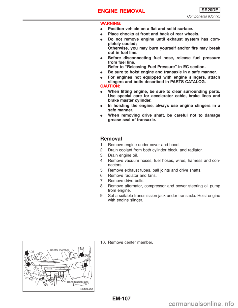
9. Set a suitable transmission jack under transaxle. Hoist engine
with engine slinger.
10. Remove center member.
SEM092D Center member
Transmission jack
ENGINE REMOVALSR20DE
Components (Cont'd)
EM-107
Page 1649 of 2267

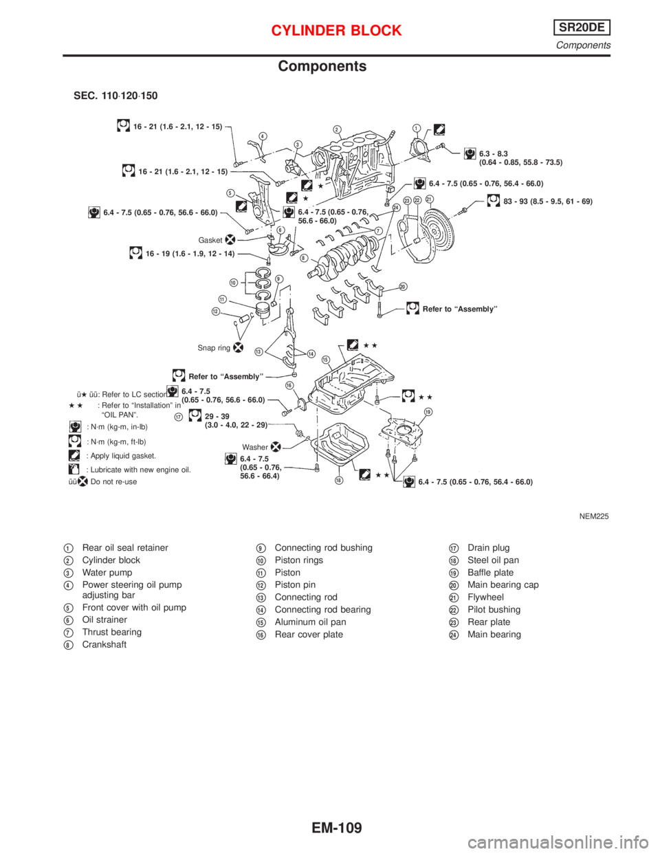
Components
p1Rear oil seal retainer
p2Cylinder block
p3Water pump
p4Power steering oil pump
adjusting bar
p5Front cover with oil pump
p6Oil strainer
p7Thrust bearing
p8Crankshaft
p9Connecting rod bushing
p10Piston rings
p11Piston
p12Piston pin
p13Connecting rod
p14Connecting rod bearing
p15Aluminum oil pan
p16Rear cover plate
p17Drain plug
p18Steel oil pan
p19Baffle plate
p20Main bearing cap
p21Flywheel
p22Pilot bushing
p23Rear plate
p24Main bearing
NEM225
p4p3
p2p1
6.3 - 8.3
(0.64 - 0.85, 55.8 - 73.5)
16 - 21 (1.6 - 2.1, 12 - 15)
p5
16 - 21 (1.6 - 2.1, 12 - 15)
6.4 - 7.5 (0.65 - 0.76, 56.6 - 66.0)
Gasket
p6
.6.4 - 7.5 (0.65 - 0.76,
56.6 - 66.0)
16 - 19 (1.6 - 1.9, 12 - 14)
p2383 - 93 (8.5 - 9.5, 61 - 69)
p10p9
p8
p22
p11
p12
Snap ringp14
Refer to ªAssemblyº
Refer to ªAssemblyº
p166.4 - 7.5
(0.65 - 0.76, 56.6 - 66.0)
p1729-39
(3.0 - 4.0, 22 - 29)
6.4 - 7.5
(0.65 - 0.76,
56.6 - 66.4) îHîî: Refer to LC section.
HH: Refer to ªInstallationº in
ªOIL PANº.
: N´m (kg-m, in-lb)
: N´m (kg-m, ft-lb)
: Apply liquid gasket.
: Lubricate with new engine oil.
îî
: Do not re-useHH
p24
Washer
p21
p20
HH
p19
6.4 - 7.5 (0.65 - 0.76, 56.4 - 66.0)
p13HH
p7
6.4 - 7.5 (0.65 - 0.76, 56.4 - 66.0).H
H
SEC. 110×120×150
p15
p18
CYLINDER BLOCKSR20DE
Components
EM-109
Page 1650 of 2267

CAUTION:
IWhen installing sliding parts (bearings, pistons, etc.),
apply new engine oil to the sliding surfaces.
IPlace removed parts such as bearings and bearing caps
in their correct order and direction.
IWhen installing connecting rod nuts and main bearing cap
bolts, apply new engine oil to threads and seating sur-
faces.
IDo not allow any magnetic materials to contact the ring
gear teeth of flywheel/drive plate.
Disassembly
PISTON AND CRANKSHAFT
1. Place engine on a work stand.
2. Remove cylinder head.
Refer to ªRemovalº in ªCYLINDER HEADº (EM-87).
3. Remove oil pan.
Refer to ªRemovalº in ªOIL PANº (EM-70).
4. Remove timing chain.
Refer to ªRemovalº in ªTIMING CHAINº (EM-76).
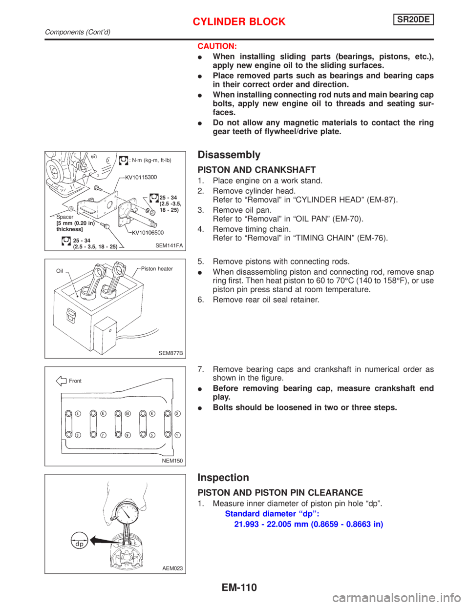
5. Remove pistons with connecting rods.
IWhen disassembling piston and connecting rod, remove snap
ring first. Then heat piston to 60 to 70ÉC (140 to 158ÉF), or use
piston pin press stand at room temperature.
6. Remove rear oil seal retainer.
7. Remove bearing caps and crankshaft in numerical order as
shown in the figure.
IBefore removing bearing cap, measure crankshaft end
play.
IBolts should be loosened in two or three steps.
Inspection
PISTON AND PISTON PIN CLEARANCE
1. Measure inner diameter of piston pin hole ªdpº.
Standard diameter ªdpº:
21.993 - 22.005 mm (0.8659 - 0.8663 in)
SEM141FA
: N´m (kg-m, ft-lb)
25-34
(2.5 -3.5,
18 - 25)
Spacer
[5 mm (0.20 in)
thickness]
25-34
(2.5 - 3.5, 18 - 25)
SEM877B Piston heater
Oil
NEM150 Front
p2
p1
p4
p3
p8
p7
p10
p9
p6
p5
AEM023
CYLINDER BLOCKSR20DE
Components (Cont'd)
EM-110
Page 1657 of 2267

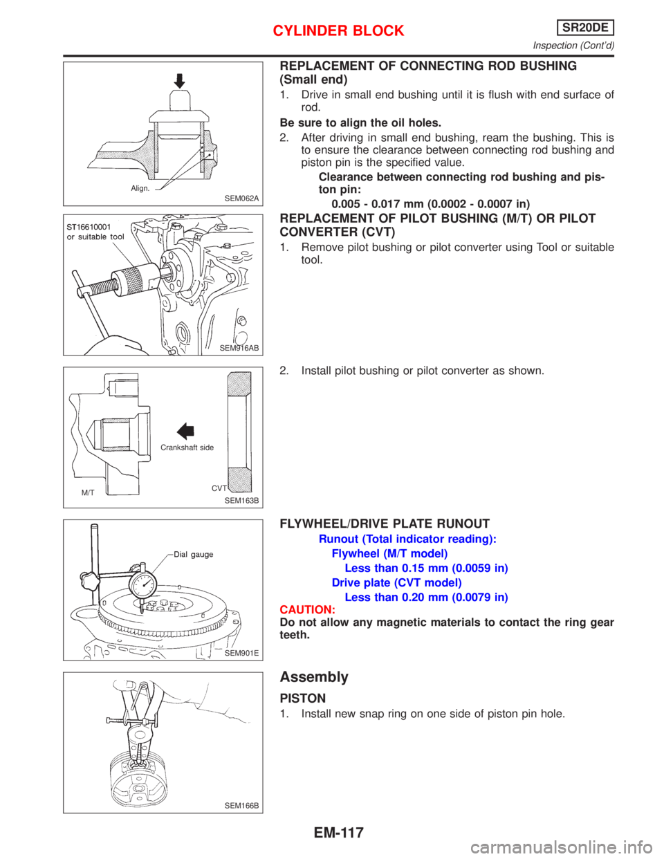
REPLACEMENT OF CONNECTING ROD BUSHING
(Small end)
1. Drive in small end bushing until it is flush with end surface of
rod.
Be sure to align the oil holes.
2. After driving in small end bushing, ream the bushing. This is
to ensure the clearance between connecting rod bushing and
piston pin is the specified value.
Clearance between connecting rod bushing and pis-
ton pin:
0.005 - 0.017 mm (0.0002 - 0.0007 in)
REPLACEMENT OF PILOT BUSHING (M/T) OR PILOT
CONVERTER (CVT)
1. Remove pilot bushing or pilot converter using Tool or suitable
tool.
2. Install pilot bushing or pilot converter as shown.
FLYWHEEL/DRIVE PLATE RUNOUT
Runout (Total indicator reading):
Flywheel (M/T model)
Less than 0.15 mm (0.0059 in)
Drive plate (CVT model)
Less than 0.20 mm (0.0079 in)
CAUTION:
Do not allow any magnetic materials to contact the ring gear
teeth.
Assembly
PISTON
1. Install new snap ring on one side of piston pin hole.
SEM062A Align.
SEM916AB
SEM163B M/TCrankshaft side
CVT
.SEM901E
SEM166B
CYLINDER BLOCKSR20DE
Inspection (Cont'd)
EM-117
Page 1679 of 2267
3. Install new oil seals with a suitable tool.
Confirm turning direction of both oil seals and camshaft.
CRANKSHAFT FRONT OIL SEAL
1. Remove valve timing belt and crankshaft sprocket.
2. Remove oil seal with a suitable tool.
3. Apply engine oil to new oil seal and install oil seal using a
suitable tool.
CRANKSHAFT REAR OIL SEAL
1. Remove transaxle assembly. (Refer to ªREMOVAL AND
INSTALLATIONº in MT section.)
2. Remove flywheel.
3. Remove rear oil seal with a suitable tool.
1. Apply engine oil to new oil seal and install oil seal using a
suitable tool.
SEM240D Rear Front
SEM889
SEM241D
SEM891
SEM242D
OIL SEAL REPLACEMENTCD20T
EM-139