Page 1698 of 2267
Inspection
Perform the following checks. If NG, replace turbocharger unit.
OIL AND WATER TUBES
Check tubes for clogging.
ROTOR SHAFT
1. Check rotor shaft for smooth rotation.
SEM366F Check for cracks
Wastegate valve actuator
Compressor wheel
Compressor housing
Center housing
Check for leaks
Check for leaks
Turbine housingTurbine wheelCheck for leaks Wastegate valve Actuator rod
SEM029F
SEM030F
TURBOCHARGERCD20T
Inspection
EM-158
Page 1699 of 2267
2. Check rotor shaft for carbon deposits.
3. Measure rotor shaft runout.
Runout (Total indicator reading):
Standard
0.056 - 0.127 mm (0.0022 - 0.0050 in)
4. Measure rotor shaft end play.
End play:
Standard
0.013 - 0.097 mm (0.0005 - 0.0038 in)
IDo not allow wheels to turn when axial play is being mea-
sured.
TURBINE WHEEL
Check turbine wheel for the following:
IOil
ICarbon deposits
IDeformed fins
IContact with turbine housing
COMPRESSOR WHEEL
Check compressor wheel for the following:
IOil
IDeformed fins
IContact with compressor housing
.SEM031F Rotor shaft
SEM032F
SEM827D
SEM828D
SEM829D
TURBOCHARGERCD20T
Inspection (Cont'd)
EM-159
Page 1703 of 2267

WARNING:
ISituate vehicle on a flat and solid surface.
IPlace chocks at front and back of rear wheels.
IDo not remove engine until exhaust system has com-
pletely cooled down.
IFor safety during subsequent steps, the tension of wires
should be slackened against the engine.
IBefore removing front axle from transaxle, place safety
stands under designated front supporting points. Refer to
GI section for lifting points and towing.
IBe sure to hoist engine and transaxle in a safe manner.
IFor engines not equipped with engine slingers, attach
proper slingers and bolts described in PARTS CATALOG
or Eurofast.
CAUTION:
IWhen lifting engine, be careful not to strike adjacent parts,
especially accelerator wire casing, brake lines, and brake
master cylinder.
IAlways use engine slingers when hoisting the engine.
IWhen removing drive shaft, be careful not to damage tran-
saxle oil seal.
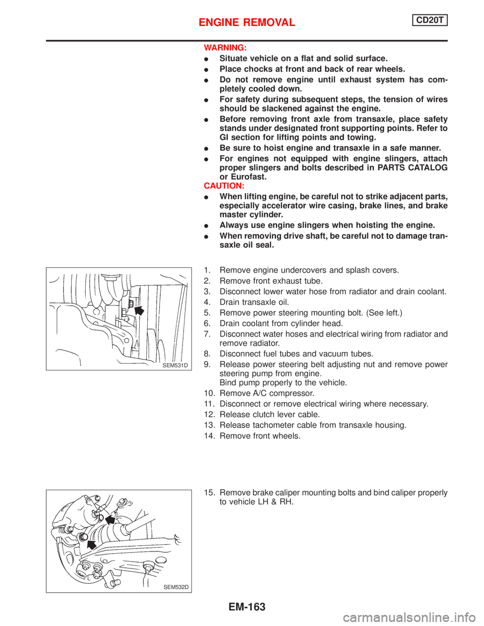
1. Remove engine undercovers and splash covers.
2. Remove front exhaust tube.
3. Disconnect lower water hose from radiator and drain coolant.
4. Drain transaxle oil.
5. Remove power steering mounting bolt. (See left.)
6. Drain coolant from cylinder head.
7. Disconnect water hoses and electrical wiring from radiator and
remove radiator.
8. Disconnect fuel tubes and vacuum tubes.
9. Release power steering belt adjusting nut and remove power
steering pump from engine.
Bind pump properly to the vehicle.
10. Remove A/C compressor.
11. Disconnect or remove electrical wiring where necessary.
12. Release clutch lever cable.
13. Release tachometer cable from transaxle housing.
14. Remove front wheels.
15. Remove brake caliper mounting bolts and bind caliper properly
to vehicle LH & RH.
.SEM531D
SEM532D
ENGINE REMOVALCD20T
EM-163
Page 1706 of 2267
Components
p1Piston ring
p2Piston
p3Piston pin
p4Connecting rod bearing
p5Connecting rod
p6Main bearing cap
p7Rear plate
p8Flywheel
p9Rear oil seal
p10Rear oil seal retainer
p11Gusset
p12Cylinder block
p13Main bearing
p14Crankshaft
p15Main bearing
p16Gusset
p17Drain plug
p18Pilot bushing
p19Plate
p20Oil jet
NEM376 54-74
(5.5 - 7.5,
40 - 54)
83-93
(8.5 - 9.5,
61 - 69)
69 - 78 (7.0 - 8.0, 51 - 58)
8.4 - 11.0 (0.86 - 1.12, 74.35 - 97.36)
30 - 40 (3.1 - 4.1, 22 - 30)
Refer to
ªAssemblyº
: Do not re-use.
: N´m (kg-m, in-lb)
îî
: N´m (kg-m, ft-lb)
î
: Lubricate with new engine oil.
SEC. 110×120
30 - 40 (3.1 - 4.1, 22 - 30)
30 - 40 (3.1 - 4.1, 266 - 354)
30-40
(3.1 - 4.1, 22 - 30)
16 - 21 (1.6 - 2.1, 12 - 15)
16 - 21 (1.6 - 2.1, 12 - 15)
CYLINDER BLOCKCD20T
Components
EM-166
Page 1717 of 2267
2. Install pistons with connecting rods.
IInstall them into corresponding cylinder using Tool.
IBe careful not to scratch cylinder wall with connecting
rod.
IApply engine oil to cylinder wall, piston and bearing.
IArrange so that the front mark on piston head faces to the
front of engine.
3. Install connecting rod bearing caps.
IApply engine oil to the thread of connecting rod bearing
nut.
(1) Tighten connecting rod bearing nut to 15 1 N´m (1.5 0.1 kg-m,
10.8 0.7 ft-lb).
(2) Then tighten an additional 60
+5É
þ0Éturns with an angular tighten-
ing wrench.
: 15 1 N´m (1.5 0.1 kg-m, 11 0.7 ft-lb) plus
60+5É
þ0Éor
: 37 - 45 N´m (3.8 - 4.6 kg-m, 27 - 33 ft-lb)
4. Measure connecting rod side clearance.
Connecting rod side clearance (Big end play):
Limit
0.3 mm (0.012 in)
FLYWHEEL RUNOUT
Runout (Total indicator reading):
Less than 0.15 mm (0.0059 in)
SEM620-A EM03470000 or suitable tool
SEM364F KV10112100
SEM365F Feeler gauge
EM426
CYLINDER BLOCKCD20T
Assembly (Cont'd)
EM-177
Page 1727 of 2267
Connecting Rod BearingNCEM0038STANDARD SIZENCEM0038S01Unit: mm (in)
Grade No. Thickness Identification color or number
0 1.503 - 1.506 (0.0592 - 0.0593) Ð
1 1.506 - 1.509 (0.0593 - 0.0594) Brown
2 1.509 - 1.512 (0.0594 - 0.0595) Green
UNDERSIZENCEM0038S02Unit: mm (in)
Grade No. Thickness Identification color or number
0.08 (0.0031) 1.542 - 1.546 (0.0607 - 0.0609) Ð
0.12 (0.0047) 1.562 - 1.566 (0.0615 - 0.0617) Ð
0.25 (0.0098) 1.627 - 1.631 (0.0641 - 0.0642) Ð
Bearing ClearanceNCEM0039Unit: mm (in)
Main bearing clearanceStandard 0.020 - 0.044 (0.0008 - 0.0017)
Limit 0.1 (0.004)
Connecting rod bearing clearanceStandard 0.014 - 0.039 (0.0006 - 0.0015)
Limit 0.1 (0.004)
Miscellaneous ComponentsNCEM0040Unit: mm (in)
Flywheel runout [TIR*]Less than 0.15 (0.0059)
Camshaft sprocket runout [TIR*] Less than 0.15 (0.0059)
*: Total indicator reading
SERVICE DATA AND SPECIFICATIONS (SDS)QG
Connecting Rod Bearing
EM-187
Page 1735 of 2267

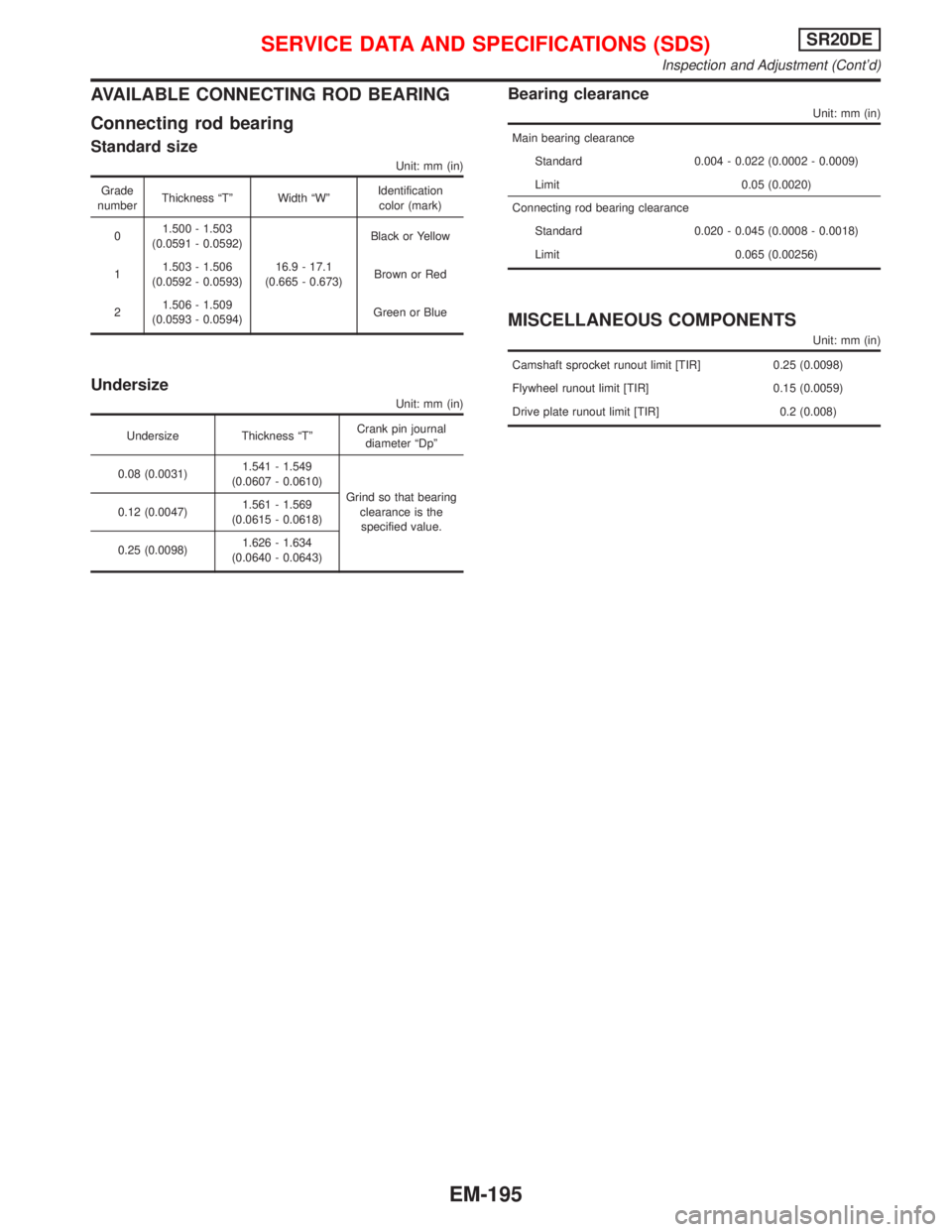
AVAILABLE CONNECTING ROD BEARING
Connecting rod bearing
Standard size
Unit: mm (in)
Grade
numberThickness ªTº Width ªWºIdentification
color (mark)
01.500 - 1.503
(0.0591 - 0.0592)
16.9 - 17.1
(0.665 - 0.673)Black or Yellow
11.503 - 1.506
(0.0592 - 0.0593)Brown or Red
21.506 - 1.509
(0.0593 - 0.0594)Green or Blue
Undersize
Unit: mm (in)
Undersize Thickness ªTºCrank pin journal
diameter ªDpº
0.08 (0.0031)1.541 - 1.549
(0.0607 - 0.0610)
Grind so that bearing
clearance is the
specified value. 0.12 (0.0047)1.561 - 1.569
(0.0615 - 0.0618)
0.25 (0.0098)1.626 - 1.634
(0.0640 - 0.0643)
Bearing clearance
Unit: mm (in)
Main bearing clearance
Standard 0.004 - 0.022 (0.0002 - 0.0009)
Limit 0.05 (0.0020)
Connecting rod bearing clearance
Standard 0.020 - 0.045 (0.0008 - 0.0018)
Limit 0.065 (0.00256)
MISCELLANEOUS COMPONENTS
Unit: mm (in)
Camshaft sprocket runout limit [TIR] 0.25 (0.0098)
Flywheel runout limit [TIR] 0.15 (0.0059)
Drive plate runout limit [TIR] 0.2 (0.008)
SERVICE DATA AND SPECIFICATIONS (SDS)SR20DE
Inspection and Adjustment (Cont'd)
EM-195
Page 1741 of 2267

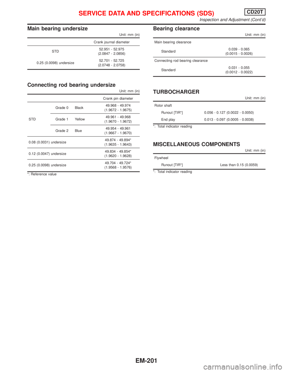
Main bearing undersize
Unit: mm (in)
Crank journal diameter
STD52.951 - 52.975
(2.0847 - 2.0856)
0.25 (0.0098) undersize52.701 - 52.725
(2.0748 - 2.0758)
Connecting rod bearing undersize
Unit: mm (in)
Crank pin diameter
STDGrade 0 Black49.968 - 49.974
(1.9672 - 1.9675)
Grade 1 Yellow49.961 - 49.968
(1.9670 - 1.9672)
Grade 2 Blue49.954 - 49.961
(1.9667 - 1.9670)
0.08 (0.0031) undersize49.874 - 49.894*
(1.9635 - 1.9643)
0.12 (0.0047) undersize49.834 - 49.854*
(1.9620 - 1.9628)
0.25 (0.0098) undersize49.704 - 49.724*
(1.9568 - 1.9576)
*: Reference value
Bearing clearance
Unit: mm (in)
Main bearing clearance
Standard0.039 - 0.065
(0.0015 - 0.0026)
Connecting rod bearing clearance
Standard0.031 - 0.055
(0.0012 - 0.0022)
TURBOCHARGER
Unit: mm (in)
Rotor shaft
Runout [TIR*] 0.056 - 0.127 (0.0022 - 0.0050)
End play 0.013 - 0.097 (0.0005 - 0.0038)
*: Total indicator reading
MISCELLANEOUS COMPONENTS
Unit: mm (in)
Flywheel
Runout [TIR*] Less than 0.15 (0.0059)
*: Total indicator reading
SERVICE DATA AND SPECIFICATIONS (SDS)CD20T
Inspection and Adjustment (Cont'd)
EM-201