Page 1753 of 2267

Wheel Hub and Knuckle
REMOVAL
CAUTION:
Before removing front axle assembly, disconnect ABS wheel
sensor from assembly and move it from front axle assem-
bly area.
Failure to do so may result in damage to sensor wires and
the sensor becoming inoperative.
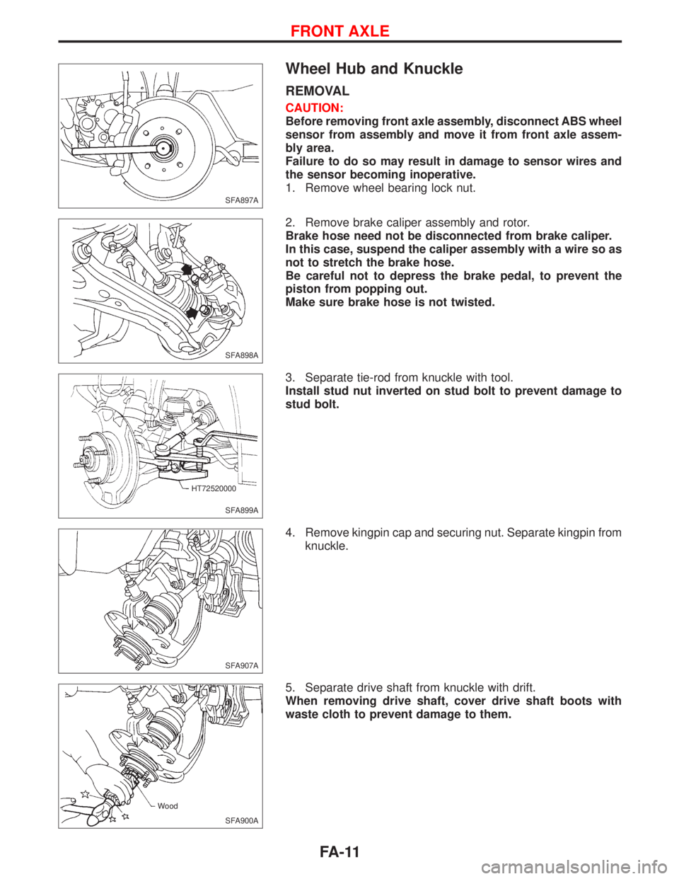
1. Remove wheel bearing lock nut.
2. Remove brake caliper assembly and rotor.
Brake hose need not be disconnected from brake caliper.
In this case, suspend the caliper assembly with a wire so as
not to stretch the brake hose.
Be careful not to depress the brake pedal, to prevent the
piston from popping out.
Make sure brake hose is not twisted.
3. Separate tie-rod from knuckle with tool.
Install stud nut inverted on stud bolt to prevent damage to
stud bolt.
4. Remove kingpin cap and securing nut. Separate kingpin from
knuckle.
5. Separate drive shaft from knuckle with drift.
When removing drive shaft, cover drive shaft boots with
waste cloth to prevent damage to them.
SFA897A
SFA898A
SFA899A HT72520000
SFA907A
SFA900A Wood
FRONT AXLE
FA-11
Page 1754 of 2267
lRemove ball joint securing nut. Separate from knuckle using
Tool (as for tie-rod).
INSTALLATION
lInstall knuckle with wheel hub.
lTighten wheel bearing lock nut.
: 236 - 313 N´m
(24 - 32 kg-m, 174 - 230 ft-lb)
lCheck that wheel bearings operate smoothly.
lCheck wheel bearing axial end play.
Axial end play:
0.05 mm (0.0020 in) or less.
DISASSEMBLY
CAUTION:
When removing wheel hub or wheel bearing from knuckle,
replace wheel bearing assembly (outer race, inner races and
grease seals) with a new one.
Wheel Hub
Drive out hub with inner race (outside) from knuckle with a suit-
able tool.
Wheel Bearing
When replacing wheel bearing, replace complete wheel
bearing assembly (including inner and outer races).
lRemove bearing inner race (outside), then remove outer
grease seal.
SFA901A HT72520000
SFA906A
SFA902A
SFA903A Suitable tool
SFA654A Suitable tool
FRONT AXLE
Wheel Hub and Knuckle (Cont'd)
FA-12
Page 1755 of 2267
lRemove inner grease seal from knuckle.
lRemove inner and outer snap rings.
lPress out bearing outer race.
INSPECTION
Wheel Hub and Knuckle
Check wheel hub and knuckle for cracks by using a magnetic
exploration or dyeing test.
Snap Ring
Check snap ring for wear or cracks. Replace if necessary.
ASSEMBLY
1. Install inner snap ring into groove of knuckle.
2. Press new wheel bearing assembly into knuckle until it con-
tacts snap ring.
Maximum load P:
49 kN (5 t, 5.5 US ton, 4.9 lmp ton)
CAUTION:
lDo not press inner race of wheel bearing assembly.
lDo not apply oil or grease to mating surfaces of wheel
bearing outer race and knuckle.
3. Install outer snap ring into groove of knuckle.
SFA904A
SFA685 Suitable tool
SFA905A Suitable tool
SFA655A Suitable tool
Wheel bearing
assembly
Knuckle
Inner snap ring
Suitable tool
FRONT AXLE
Wheel Hub and Knuckle (Cont'd)
FA-13
Page 1756 of 2267
4. Pack grease seal lip with multi-purpose grease.
5. Install outer grease seal.
Maximum load P:
10 kN (1 ton, 1.1 US ton, 1.0 Imp ton)
6. Install inner grease seal.
Maximum load P:
10 kN (1 ton, 1.1 US ton, 1.0 Imp ton)
7. Press wheel hub into knuckle.
Maximum load P:
29 kN (3 ton, 3.3 US ton, 3.0 Imp ton)
Be careful not to damage grease seal.
8. Check bearing operation.
(1) Add load P with press.
Load P:
34.3 - 49.0 kN
(3.5 - 5.0 ton, 3.9 - 5.5 US ton, 3.44 - 4.92 Imp ton)
SFA747 Inner side
SFA656A Suitable tool
Grease seal
SFA657A Suitable tool
Grease seal
Suitable tool
SFA658A Wheel
bearing
assemblySuitable tool
Wheel hub
Knuckle
Suitable tool
SFA659A
FRONT AXLE
Wheel Hub and Knuckle (Cont'd)
FA-14
Page 1757 of 2267
(2) Spin knuckle several turns in both directions.
(3) Make sure that wheel bearings operate smoothly.
Drive shaft
REMOVAL
1. Remove wheel bearing lock nut.
2. Remove brake caliper assembly and rotor.
Brake hose need not be disconnected from brake caliper. In
this case, suspend caliper assembly with wire so as not to
stretch brake hose. Be careful not to depress brake pedal,
or piston will pop out.
Make sure brake hose is not twisted.
3. Remove tie-rod ball joint.
4. Remove upper knuckle nut.
5. Separate drive shaft from knuckle by lightly tapping it. If it is
hard to remove, use a puller.
When removing drive shaft, cover drive shaft boots with
waste cloth to prevent damage to them.
Refer to ªFRONT AXLEº, ªWheel Hub and Knuckleº, FA-11.
6. Remove right drive shaft from transaxle.
þ Models without support bearing þ
þ Models with support bearing þ
SFA182A
SFA897A
SFA907A
.SFA499A
.SFA989
FRONT AXLE
Wheel Hub and Knuckle (Cont'd)
FA-15
Page 1759 of 2267
Wheel side
lInstall drive shaft into knuckle.
lTighten upper knuckle nut and wheel bearing lock nut. Refer
to ªFRONT AXLEº, ªWheel Hub and Knuckleº, FA-11.
COMPONENTS
NFA054
Wheel side
(90AC type and 98AC type)Spacer ring
ABS rotor
Boot band
Drive shaft
Boot
Spider assembly Circulair clip:
Make sure circular clip is properly meshed with side gear
(transaxle side) and joint assembly (wheel side), and will
not come out.
Be careful not to damage boots. Use suitable protector
or cloth during removal and installation.
All M/T modelsJoint assembly
Boot
Circular clip B
Boot band
Snap ring C
Side joint housing
Dust shield
Circular clip
Transaxle side
(GI69 type and GI82 type) SEC. 391
FRONT AXLE
Drive shaft (Cont'd)
FA-17
Page 1760 of 2267
p1Joint assembly
p2Boot band
p3Boot
p4Circular clip B
p5Drive shaft
p6Boot band
p7Boot
p8Snap ring A
p9Snap ring B
p10Inner race
p11Cage
p12Ball
p13Snap ring C
p14Slide joint housing
p15Dust shield
p16Circular clip A
p17Slide joint housing with
extention shaft
p18Snap ring E
p19Dust shield
p20Support bearing
p21Support bearing retainer
p22Bracket
p23Snap ring D
p24Dust shield
NFA055 For type with support bearing Circular clip:
Make sure circular clip is properly meshed with side gear (transaxle
side) and joint assembly (wheel side), and will not come out.
Wheel side (B86 type)
Right drive shaftTransaxle side (D83/T83 type)
25 - 35 (2.6 - 3.6, 19 - 26)
25 - 35 (2.6 - 3.6, 19 - 26)
43-58
(4.4 - 5.9, 32 - 43)
13 - 19 (1.3 - 1.9, 9 - 14)
: N´m (kg-m, ft-lb)Left drive shaft All CVT models Be careful not to damage boots. Use suitable protector
or cloth during removal and installation.
FRONT AXLE
Drive shaft (Cont'd)
FA-18
Page 1761 of 2267

DISASSEMBLY
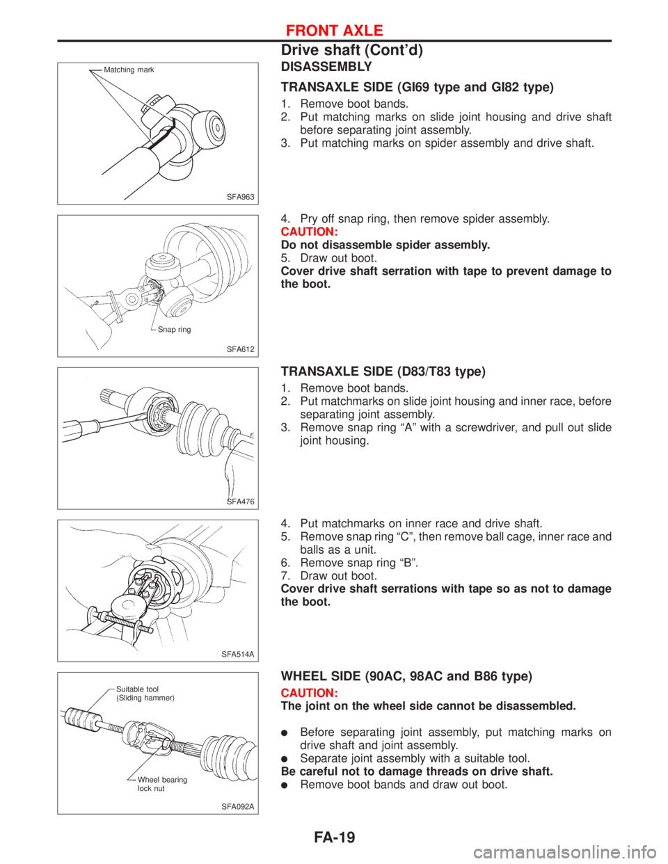
TRANSAXLE SIDE (GI69 type and GI82 type)
1. Remove boot bands.
2. Put matching marks on slide joint housing and drive shaft
before separating joint assembly.
3. Put matching marks on spider assembly and drive shaft.
4. Pry off snap ring, then remove spider assembly.
CAUTION:
Do not disassemble spider assembly.
5. Draw out boot.
Cover drive shaft serration with tape to prevent damage to
the boot.
TRANSAXLE SIDE (D83/T83 type)
1. Remove boot bands.
2. Put matchmarks on slide joint housing and inner race, before
separating joint assembly.
3. Remove snap ring ªAº with a screwdriver, and pull out slide
joint housing.
4. Put matchmarks on inner race and drive shaft.
5. Remove snap ring ªCº, then remove ball cage, inner race and
balls as a unit.
6. Remove snap ring ªBº.
7. Draw out boot.
Cover drive shaft serrations with tape so as not to damage
the boot.
WHEEL SIDE (90AC, 98AC and B86 type)
CAUTION:
The joint on the wheel side cannot be disassembled.
lBefore separating joint assembly, put matching marks on
drive shaft and joint assembly.
lSeparate joint assembly with a suitable tool.
Be careful not to damage threads on drive shaft.
lRemove boot bands and draw out boot.
SFA963 Matching mark
SFA612 Snap ring
SFA476
SFA514A
SFA092A Suitable tool
(Sliding hammer)
Wheel bearing
lock nut
FRONT AXLE
Drive shaft (Cont'd)
FA-19