1999 NISSAN PRIMERA wheel
[x] Cancel search: wheelPage 1763 of 2267
INSPECTION
Thoroughly clean all parts in cleaning solvent, and dry with com-
pressed air. Check parts for evidence of deformation or other
damage.
Drive shaft
Replace drive shaft if it is twisted or cracked.
Boot
Check boot for fatigue, cracks or wear. Replace boot with new
boot bands.
Joint assembly (Transaxle side)
GI69 and GI82 type
lCheck spider assembly for needle bearing and washer dam-
age. Replace if necessary.
lCheck roller surfaces for scratches, wear or other damage.
Replace if necessary.
lCheck serration for deformation. Replace if necessary.
lCheck slide joint housing for any damage. Replace if neces-
sary.
D83/T83 type
lReplace joint assembly if it is deformed or damaged.
Joint assembly (Wheel side)
Replace joint assembly if it is deformed or damaged.
Support bearing
Make sure bearing rolls freely, and is free from noise, cracks,
pitting or wear.
Support bearing bracket
Check support bearing bracket for cracks with a magnetic explo-
ration or dyeing test.
ASSEMBLY
lAfter drive shaft has been assembled, ensure that it
moves smoothly over its entire range without binding.
lUse NISSAN GENUINE GREASE or equivalent after every
overhaul.
FRONT AXLE
Drive shaft (Cont'd)
FA-21
Page 1764 of 2267
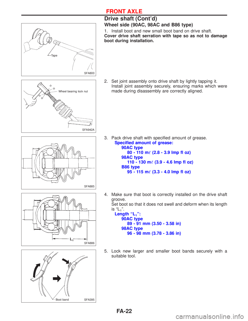
Wheel side (90AC, 98AC and B86 type)
1. Install boot and new small boot band on drive shaft.
Cover drive shaft serration with tape so as not to damage
boot during installation.
2. Set joint assembly onto drive shaft by lightly tapping it.
Install joint assembly securely, ensuring marks which were
made during disassembly are correctly aligned.
3. Pack drive shaft with specified amount of grease.
Specified amount of grease:
90AC type
80 - 110 m(2.8 - 3.9 Imp fl oz)
98AC type
110 - 130 m(3.9 - 4.6 Imp fl oz)
B86 type
95 - 115 m(3.3 - 4.0 Imp fl oz)
4. Make sure that boot is correctly installed on the drive shaft
groove.
Set boot so that it does not swell and deform when its length
is ªL
1º.
Length ªL
1º:
90AC type
89 - 91 mm (3.50 - 3.58 in)
98AC type
96 - 98 mm (3.78 - 3.86 in)
5. Lock new larger and smaller boot bands securely with a
suitable tool.
SFA800 Tape
SFA942A Wheel bearing lock nut
SFA885
SFA886L1
SFA395 Boot band
FRONT AXLE
Drive shaft (Cont'd)
FA-22
Page 1768 of 2267
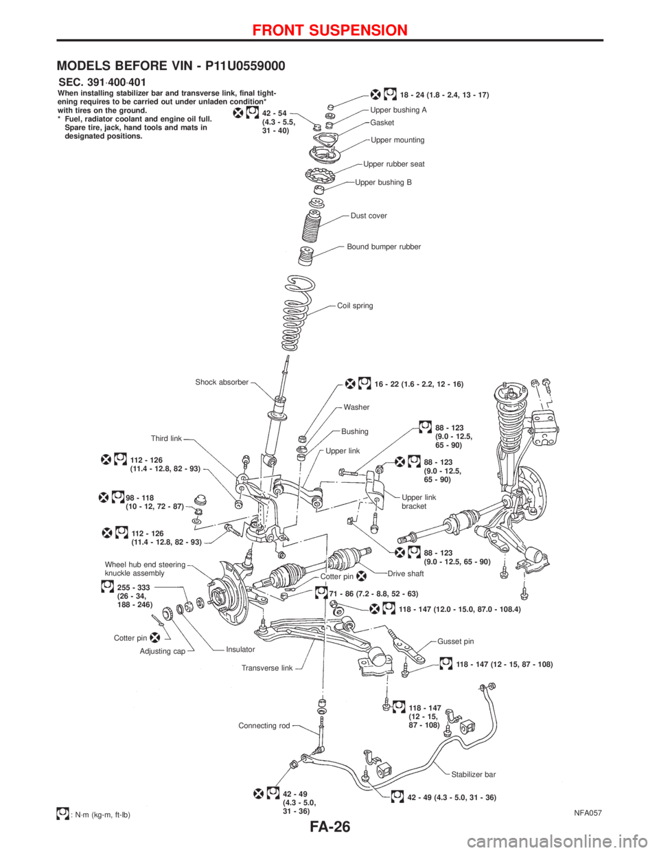
MODELS BEFORE VIN - P11U0559000
NFA057 When installing stabilizer bar and transverse link, final tight-
ening requires to be carried out under unladen condition*
with tires on the ground.
* Fuel, radiator coolant and engine oil full.
Spare tire, jack, hand tools and mats in
designated positions.
42-54
(4.3 - 5.5,
31 - 40)
18 - 24 (1.8 - 2.4, 13 - 17)
Upper bushing A
Gasket
Upper mounting
Upper rubber seat
Upper bushing B
Dust cover
Bound bumper rubber
Coil spring
16 - 22 (1.6 - 2.2, 12 - 16)
Washer
Bushing
Upper link
88 - 123
(9.0 - 12.5,
65 - 90)
88 - 123
(9.0 - 12.5,
65 - 90)
Upper link
bracket
88 - 123
(9.0 - 12.5, 65 - 90)
Drive shaft
Cotter pin.71 - 86 (7.2 - 8.8, 52 - 63)
118 - 147 (12.0 - 15.0, 87.0 - 108.4)
Gusset pin
118 - 147 (12 - 15, 87 - 108)
118 - 147
(12 - 15,
87 - 108)
Stabilizer bar
42 - 49 (4.3 - 5.0, 31 - 36)42-49
(4.3 - 5.0,
31 - 36) Connecting rodTransverse link Insulator
Adjusting cap Cotter pin
255 - 333
(26 - 34,
188 - 246) Wheel hub end steering
knuckle assembly
112 - 126
(11.4 - 12.8, 82 - 93)
98-118
(10 - 12, 72 - 87)
112 - 126
(11.4 - 12.8, 82 - 93)Third linkShock absorber
: N´m (kg-m, ft-lb)
SEC. 391×400×401
FRONT SUSPENSION
FA-26
Page 1774 of 2267

Transverse Link and Lower Ball Joint
REMOVAL AND INSTALLATION
lRemove tension rod, ball joint and transverse link assembly.
lDuring installation, final tightening must be done at curb
weight with tires on ground.
lAfter installation, check wheel alignment.
Refer to ªFront Wheel Alignmentº, ªON-VEHICLE SER-
VICEº, FA-6.
INSPECTION
Transverse link
lCheck transverse link for damage, cracks or deformation.
Replace it if necessary.
lCheck rubber bushing for damage, cracks and deformation.
Replace transverse link if necessary.
Lower ball joint
lCheck ball joint for excessive play. Replace transverse link
assembly if any of the following exists:
lBall stud is worn.
lJoint is hard to swing.
lPlay in axial direction is excessive.
Before checking, turn ball joint at least 10 revolutions so that
ball joint is properly broken in.
Swinging force ªAº:
(measuring point: cotter pin hole of ball stud)
7.8 - 57.9 N (0.8 - 5.9 kg, 1.8 - 13.0 lb)
Turning torque ªBº:
0.5 - 3.4 (5 - 35 kg-cm, 4.3 - 30.4 in-lb)
Vertical end play ªCº:
0mm(0in)
lCheck dust cover for damage. Replace it and cover clamp if
necessary.
Stabilizer Bar
REMOVAL AND INSTALLATION
CAUTION:
Ð For models with xenon headlamps only
lWhen removing or installing stabilizer bar, take care not
to damage headlamp leveling sensor.
lAfter installation of the stabilizer bar, the headlamp sen-
sor has to be recalibrated. Refer to EL-section.
lRemove stabilizer bar.
NFA036
SFA858A A
B
C
.SFA925A
FRONT SUSPENSION
FA-32
Page 1776 of 2267
General Specifications
Suspension type Independent multi-link strut with coil spring
Strut type Double-acting hydraulic
Stabilizer bar Standard equipment
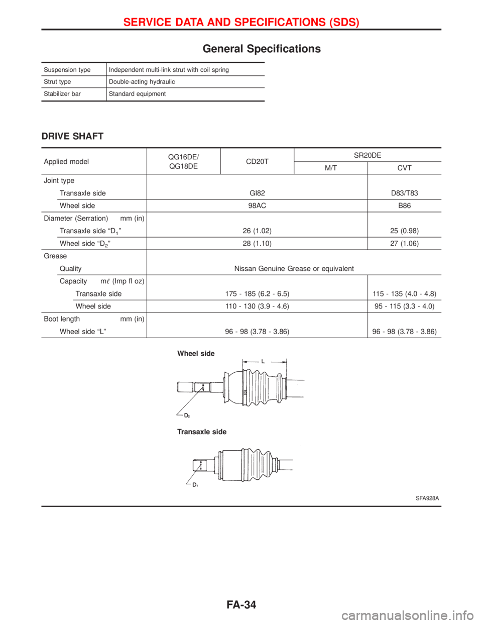
DRIVE SHAFT
Applied modelQG16DE/
QG18DECD20TSR20DE
M/T CVT
Joint type
Transaxle side GI82 D83/T83
Wheel side 98AC B86
Diameter (Serration) mm (in)
Transaxle side ªD
1º 26 (1.02) 25 (0.98)
Wheel side ªD
2º 28 (1.10) 27 (1.06)
Grease
Quality Nissan Genuine Grease or equivalent
Capacity m(Imp fl oz)
Transaxle side 175 - 185 (6.2 - 6.5) 115 - 135 (4.0 - 4.8)
Wheel side 110 - 130 (3.9 - 4.6) 95 - 115 (3.3 - 4.0)
Boot length mm (in)
Wheel side ªLº 96 - 98 (3.78 - 3.86) 96 - 98 (3.78 - 3.86)
SFA928A
Wheel side
Transaxle side
SERVICE DATA AND SPECIFICATIONS (SDS)
FA-34
Page 1777 of 2267
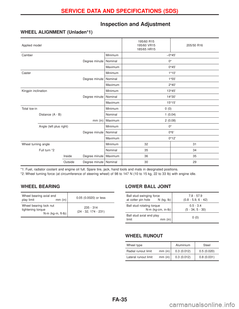
Inspection and Adjustment
WHEEL ALIGNMENT (Unladen*1)
Applied model195/60 R15
195/60 VR15
185/65 HR15205/50 R16
Camber Minimum þ0É45¢
Degree minute Nominal 0É
Maximum 0É45¢
Caster Minimum 1É10¢
Degree minute Nominal 1É55¢
Maximum 2É40¢
Kingpin inclination Minimum 13É45¢
Degree minute Nominal 14É30¢
Maximum 15É15¢
Total toe-in Minimum 0 (0)
Distance (A - B) Nominal 1 (0.04)
mm (in) Maximum 2 (0.08)
Angle (left plus right) Minimum 0É
Degree minute Nominal 0É6¢
Maximum 0É12¢
Wheel turning angle Minimum 32 31
Full turn *2 Nominal 35 34
Inside Degree minute Maximum 36 35
Outside Degree minute Nominal 30 29
*1: Fuel, radiator coolant and engine oil full. Spare tire, jack, hand tools and mats in designated positions.
*2: Wheel turning force (at circumference of steering wheel) of 98 to 147 N (10 to 15 kg, 22 to 33 lb) with engine idle.
WHEEL BEARING
Wheel bearing axial end
play limit mm (in)0.05 (0.0020) or less
Wheel bearing lock nut
tightening torque
N´m (kg-m, ft-lb)235 - 314
(24 - 32, 174 - 231)
LOWER BALL JOINT
Ball stud swinging force
at cotter pin hole N (kg, lb)7.8 - 57.9
(0.8 - 5.9, 6 - 42)
Ball stud rotating torque
N´m (kg-cm, in-lb)0.5 - 3.4
(5 - 34, 5 - 30)
Ball stud axial end play
limit mm (in)0 (0)
WHEEL RUNOUT
Wheel type Aluminium Steel
Radial runout limit mm (in) 0.3 (0.012) 0.5 (0.020)
Lateral runout limit mm (in) 0.3 (0.012) 0.8 (0.031)
SERVICE DATA AND SPECIFICATIONS (SDS)
FA-35
Page 1796 of 2267
GENERAL INFORMATION
SECTION
GI
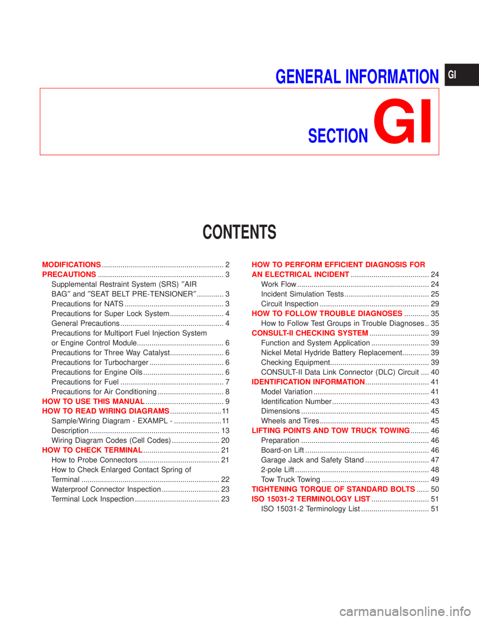
CONTENTS
MODIFICATIONS........................................................... 2
PRECAUTIONS............................................................. 3
Supplemental Restraint System (SRS)²AIR
BAG²and²SEAT BELT PRE-TENSIONER²............. 3
Precautions for NATS ................................................ 3
Precautions for Super Lock System .......................... 4
General Precautions .................................................. 4
Precautions for Multiport Fuel Injection System
or Engine Control Module.......................................... 6
Precautions for Three Way Catalyst.......................... 6
Precautions for Turbocharger .................................... 6
Precautions for Engine Oils ....................................... 6
Precautions for Fuel .................................................. 7
Precautions for Air Conditioning ................................ 8
HOW TO USE THIS MANUAL...................................... 9
HOW TO READ WIRING DIAGRAMS......................... 11
Sample/Wiring Diagram - EXAMPL - ....................... 11
Description ............................................................... 13
Wiring Diagram Codes (Cell Codes) ....................... 20
HOW TO CHECK TERMINAL..................................... 21
How to Probe Connectors ....................................... 21
How to Check Enlarged Contact Spring of
Terminal ................................................................... 22
Waterproof Connector Inspection ............................ 23
Terminal Lock Inspection ......................................... 23HOW TO PERFORM EFFICIENT DIAGNOSIS FOR
AN ELECTRICAL INCIDENT...................................... 24
Work Flow ................................................................ 24
Incident Simulation Tests ......................................... 25
Circuit Inspection ..................................................... 29
HOW TO FOLLOW TROUBLE DIAGNOSES............ 35
How to Follow Test Groups in Trouble Diagnoses .. 35
CONSULT-II CHECKING SYSTEM............................. 39
Function and System Application ............................ 39
Nickel Metal Hydride Battery Replacement............. 39
Checking Equipment................................................ 39
CONSULT-II Data Link Connector (DLC) Circuit .... 40
IDENTIFICATION INFORMATION............................... 41
Model Variation ........................................................ 41
Identification Number ............................................... 43
Dimensions .............................................................. 45
Wheels and Tires ..................................................... 45
LIFTING POINTS AND TOW TRUCK TOWING......... 46
Preparation .............................................................. 46
Board-on Lift ............................................................ 46
Garage Jack and Safety Stand ............................... 47
2-pole Lift ................................................................. 48
Tow Truck Towing .................................................... 49
TIGHTENING TORQUE OF STANDARD BOLTS...... 50
ISO 15031-2 TERMINOLOGY LIST............................ 51
ISO 15031-2 Terminology List ................................. 51
GI
Page 1798 of 2267
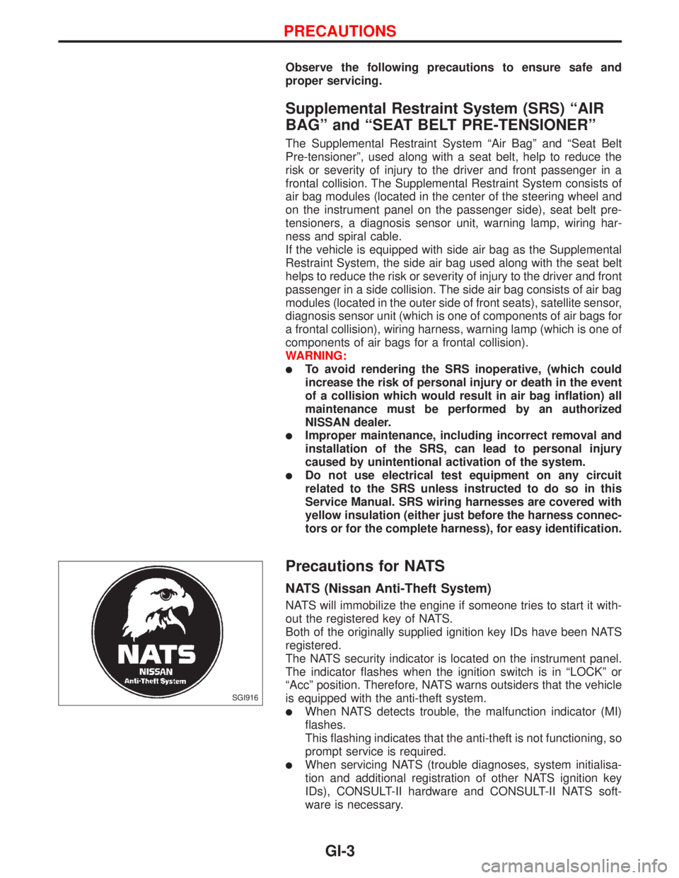
Observe the following precautions to ensure safe and
proper servicing.
Supplemental Restraint System (SRS) ªAIR
BAGº and ªSEAT BELT PRE-TENSIONERº
The Supplemental Restraint System ªAir Bagº and ªSeat Belt
Pre-tensionerº, used along with a seat belt, help to reduce the
risk or severity of injury to the driver and front passenger in a
frontal collision. The Supplemental Restraint System consists of
air bag modules (located in the center of the steering wheel and
on the instrument panel on the passenger side), seat belt pre-
tensioners, a diagnosis sensor unit, warning lamp, wiring har-
ness and spiral cable.
If the vehicle is equipped with side air bag as the Supplemental
Restraint System, the side air bag used along with the seat belt
helps to reduce the risk or severity of injury to the driver and front
passenger in a side collision. The side air bag consists of air bag
modules (located in the outer side of front seats), satellite sensor,
diagnosis sensor unit (which is one of components of air bags for
a frontal collision), wiring harness, warning lamp (which is one of
components of air bags for a frontal collision).
WARNING:
lTo avoid rendering the SRS inoperative, (which could
increase the risk of personal injury or death in the event
of a collision which would result in air bag inflation) all
maintenance must be performed by an authorized
NISSAN dealer.
lImproper maintenance, including incorrect removal and
installation of the SRS, can lead to personal injury
caused by unintentional activation of the system.
lDo not use electrical test equipment on any circuit
related to the SRS unless instructed to do so in this
Service Manual. SRS wiring harnesses are covered with
yellow insulation (either just before the harness connec-
tors or for the complete harness), for easy identification.
Precautions for NATS
NATS (Nissan Anti-Theft System)
NATS will immobilize the engine if someone tries to start it with-
out the registered key of NATS.
Both of the originally supplied ignition key IDs have been NATS
registered.
The NATS security indicator is located on the instrument panel.
The indicator flashes when the ignition switch is in ªLOCKº or
ªAccº position. Therefore, NATS warns outsiders that the vehicle
is equipped with the anti-theft system.
lWhen NATS detects trouble, the malfunction indicator (MI)
flashes.
This flashing indicates that the anti-theft is not functioning, so
prompt service is required.
lWhen servicing NATS (trouble diagnoses, system initialisa-
tion and additional registration of other NATS ignition key
IDs), CONSULT-II hardware and CONSULT-II NATS soft-
ware is necessary.
SGI916
PRECAUTIONS
GI-3