1999 NISSAN PRIMERA wheel
[x] Cancel search: wheelPage 1799 of 2267
Regarding the procedures of NATS initialisation and NATS igni-
tion key ID registration, refer to CONSULT-II operation manual
for NATS.
Therefore, CONSULT-II NATS software (program card and
operation manual) must be kept strictly confidential to main-
tain the integrity of the anti-theft function.
lWhen servicing NATS (trouble diagnoses, system initialisa-
tion and additional registration of other NATS ignition key
IDs), it may be necessary to re-register original key identifi-
cation. Therefore, be sure to obtain all keys from vehicle
owner.
A maximum of four key IDs can be registered into NATS.
Precautions for Super Lock System
Locking the driver's door or front passenger's door with the key
or remote control will lock all doors and activate the Super Lock
System.
The Super Lock System is designed to prevent theft as it can
only be released when a front door is unlocked using a key or
remote control.
This means, none of the door locks can be operated from the
inside using the door lock knob when the Super Lock System is
activated.
General Precautions
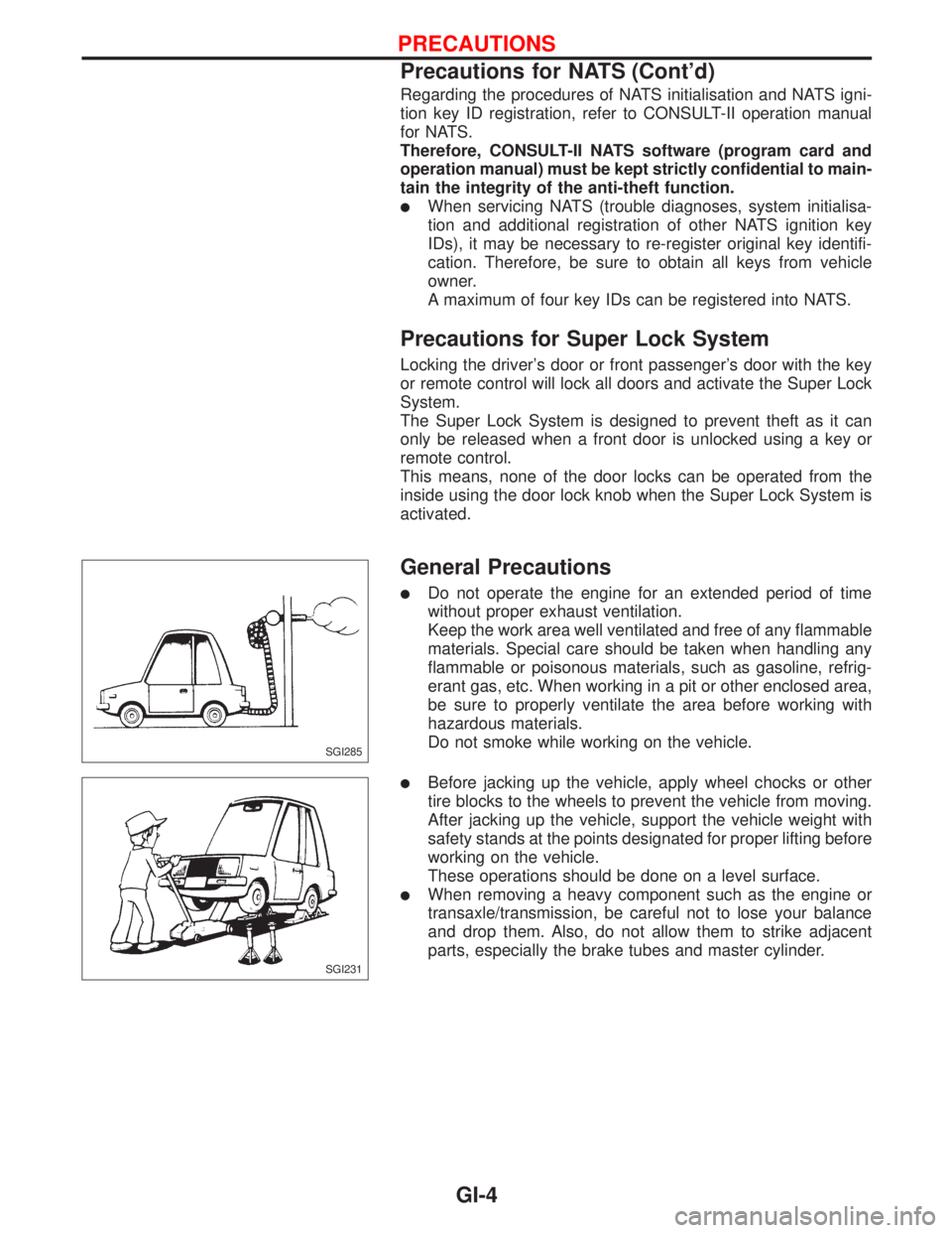
lDo not operate the engine for an extended period of time
without proper exhaust ventilation.
Keep the work area well ventilated and free of any flammable
materials. Special care should be taken when handling any
flammable or poisonous materials, such as gasoline, refrig-
erant gas, etc. When working in a pit or other enclosed area,
be sure to properly ventilate the area before working with
hazardous materials.
Do not smoke while working on the vehicle.
lBefore jacking up the vehicle, apply wheel chocks or other
tire blocks to the wheels to prevent the vehicle from moving.
After jacking up the vehicle, support the vehicle weight with
safety stands at the points designated for proper lifting before
working on the vehicle.
These operations should be done on a level surface.
lWhen removing a heavy component such as the engine or
transaxle/transmission, be careful not to lose your balance
and drop them. Also, do not allow them to strike adjacent
parts, especially the brake tubes and master cylinder.
SGI285
SGI231
PRECAUTIONS
Precautions for NATS (Cont'd)
GI-4
Page 1837 of 2267
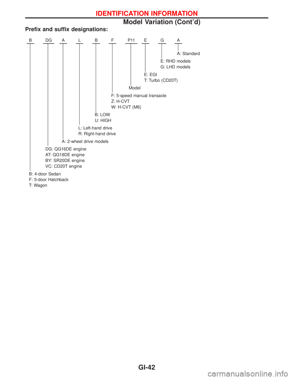
Prefix and suffix designations:
BDGALBFP11EGA
A: Standard
E: RHD models
G: LHD models
E: EGI
T: Turbo (CD20T)
Model
F: 5-speed manual transaxle
Z: H-CVT
W: H-CVT (M6)
B: LOW
U: HIGH
L: Left-hand drive
R: Right-hand drive
A: 2-wheel drive models
DG: QG16DE engine
AT: QG18DE engine
BY: SR20DE engine
VC: CD20T engine
B: 4-door Sedan
F: 5-door Hatchback
T: Wagon
IDENTIFICATION INFORMATION
Model Variation (Cont'd)
GI-42
Page 1838 of 2267
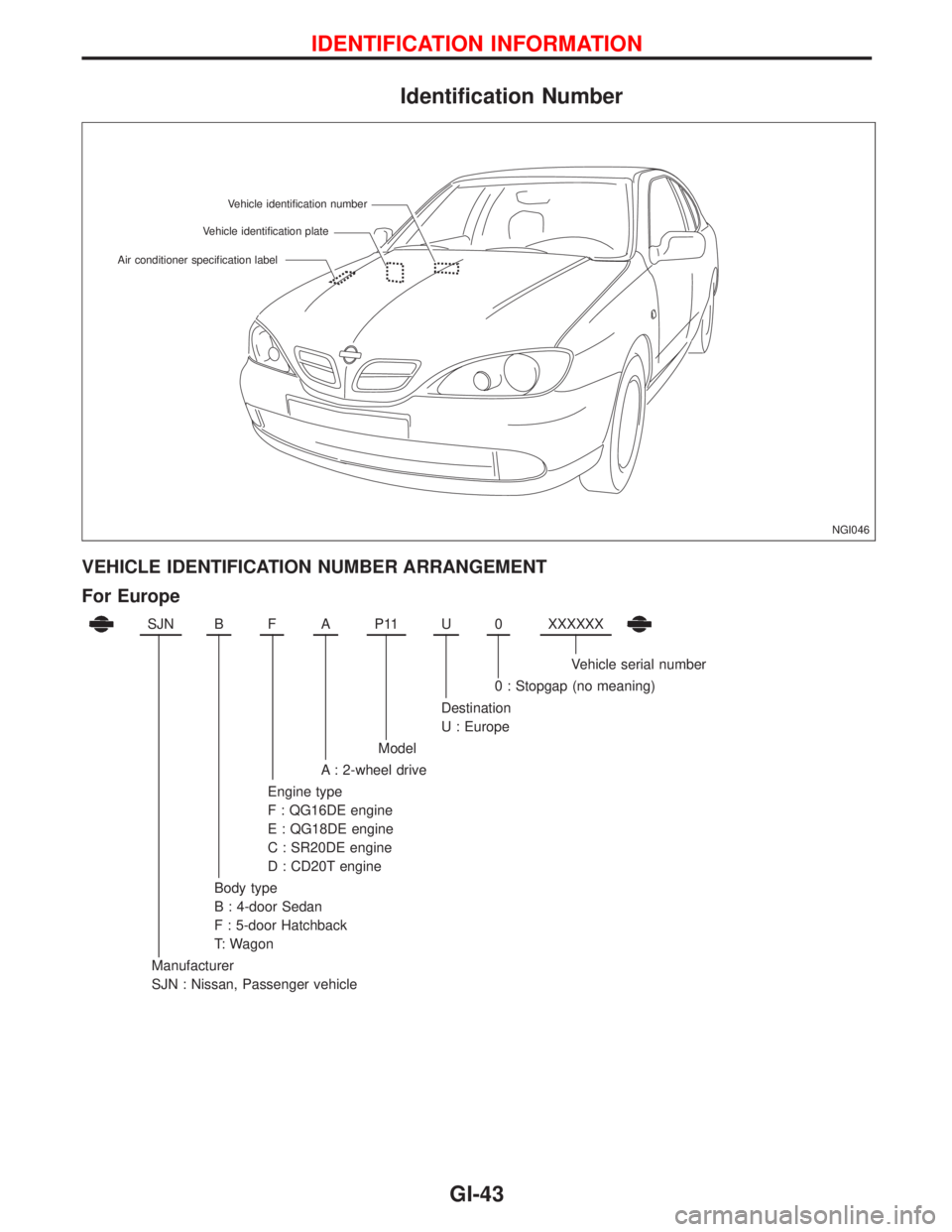
Identification Number
VEHICLE IDENTIFICATION NUMBER ARRANGEMENT
For Europe
SJNBFAP11U0XXXXXX
Vehicle serial number
0 : Stopgap (no meaning)
Destination
U : Europe
Model
A : 2-wheel drive
Engine type
F : QG16DE engine
E : QG18DE engine
C : SR20DE engine
D : CD20T engine
Body type
B : 4-door Sedan
F : 5-door Hatchback
T: Wagon
Manufacturer
SJN : Nissan, Passenger vehicle
NGI046 Vehicle identification plateVehicle identification number
Air conditioner specification label
IDENTIFICATION INFORMATION
GI-43
Page 1840 of 2267
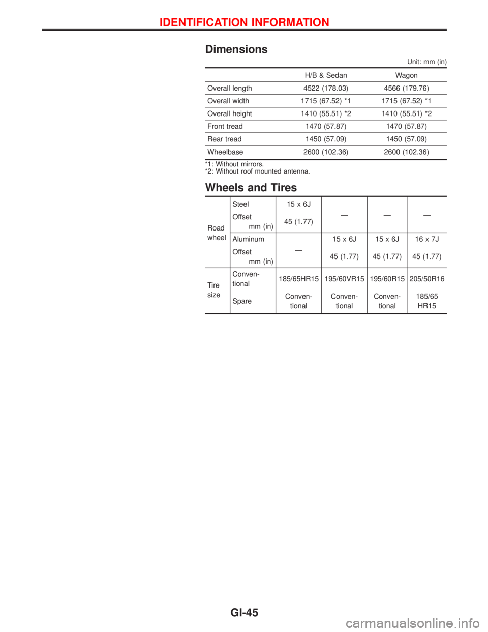
Dimensions
Unit: mm (in)
H/B & Sedan Wagon
Overall length 4522 (178.03) 4566 (179.76)
Overall width 1715 (67.52) *1 1715 (67.52) *1
Overall height 1410 (55.51) *2 1410 (55.51) *2
Front tread 1470 (57.87) 1470 (57.87)
Rear tread 1450 (57.09) 1450 (57.09)
Wheelbase 2600 (102.36) 2600 (102.36)
*1: Without mirrors.
*2: Without roof mounted antenna.
Wheels and Tires
Road
wheelSteel 15 x 6J
ÐÐÐ
Offset
mm (in)45 (1.77)
Aluminum
Ð15x6J 15x6J 16x7J
Offset
mm (in)45 (1.77) 45 (1.77) 45 (1.77)
Tire
sizeConven-
tional185/65HR15 195/60VR15 195/60R15 205/50R16
SpareConven-
tionalConven-
tionalConven-
tional185/65
HR15
IDENTIFICATION INFORMATION
GI-45
Page 1842 of 2267
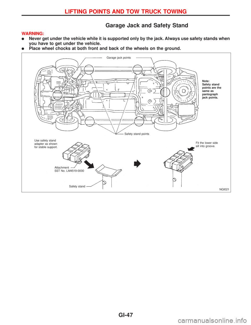
Garage Jack and Safety Stand
WARNING:
lNever get under the vehicle while it is supported only by the jack. Always use safety stands when
you have to get under the vehicle.
lPlace wheel chocks at both front and back of the wheels on the ground.
NGI021 Garage jack points
Safety stand pointsNote:
Safety stand
points are the
same as
pantograph
jack points.
Use safety stand
adapter as shown
for stable support.
Attachment
SST No. LM4519-0000
Safety standFit the lower side
sill into groove.
LIFTING POINTS AND TOW TRUCK TOWING
GI-47
Page 1844 of 2267
Tow Truck Towing
CAUTION:
lAll applicable local laws regarding the towing operation
must be obeyed.
lIt is necessary to use proper towing equipment to avoid
possible damage to the vehicle during towing operation.
Towing is in accordance with Towing Procedure Manual
at dealer.
lWhen towing with the rear wheels on the ground, release
the parking brake and move the gearshift lever to neu-
tral position.
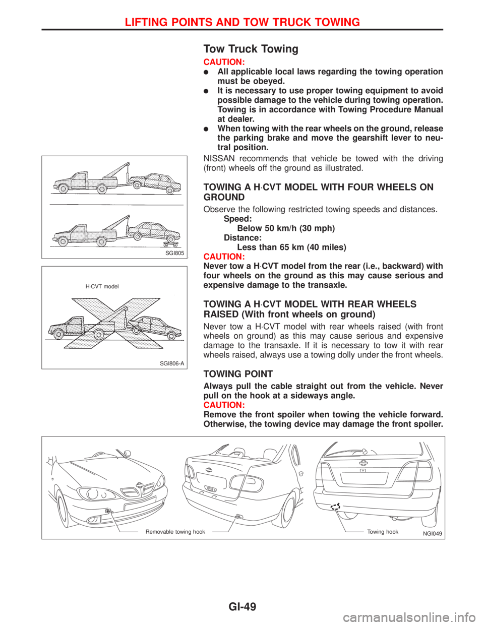
NISSAN recommends that vehicle be towed with the driving
(front) wheels off the ground as illustrated.
TOWING A H×CVT MODEL WITH FOUR WHEELS ON
GROUND
Observe the following restricted towing speeds and distances.
Speed:
Below 50 km/h (30 mph)
Distance:
Less than 65 km (40 miles)
CAUTION:
Never tow a H×CVT model from the rear (i.e., backward) with
four wheels on the ground as this may cause serious and
expensive damage to the transaxle.
TOWING A H×CVT MODEL WITH REAR WHEELS
RAISED (With front wheels on ground)
Never tow a H×CVT model with rear wheels raised (with front
wheels on ground) as this may cause serious and expensive
damage to the transaxle. If it is necessary to tow it with rear
wheels raised, always use a towing dolly under the front wheels.
TOWING POINT
Always pull the cable straight out from the vehicle. Never
pull on the hook at a sideways angle.
CAUTION:
Remove the front spoiler when towing the vehicle forward.
Otherwise, the towing device may damage the front spoiler.
SGI805
SGI806-A H×CVT model
NGI049 Towing hook Removable towing hook
LIFTING POINTS AND TOW TRUCK TOWING
GI-49
Page 1852 of 2267
Supplemental Restraint System (SRS) ªAIR
BAGº and ªSEAT BELT PRE-TENSIONERº
The Supplemental Restraint System such as ªAIR BAGº and ªSEAT BELT PRE-TENSIONERº used along
with a seat belt, helps to reduce the risk or severity of injury to the driver and front passenger for certain
types of collision. The SRS system composition which is available to NISSAN MODEL P11 is as follows (The
composition varies according to optional equipment):
lFor a frontal collision
The Supplemental Restraint System consists of driver's air bag module (located in the center of the
steering wheel), front passenger's air bag module (located on the instrument panel on passenger's side),
seat belt pre-tensioners, a diagnosis sensor unit, warning lamp, wiring harness and spiral cable.
lFor a side collision
The Supplemental Restraint System consists of front side air bag module (located in the outer side of
front seat), satellite sensor, diagnosis sensor unit (one of components of air bags for a frontal collision),
wiring harness, warning lamp (one of components of air bags for a frontal collision).
Information necessary to service the system safely is included in theRS sectionof this Service Manual.
WARNING:
lTo avoid rendering the SRS inoperative, which could increase the risk of personal injury or death
in the event of a collision which would result in air bag inflation, all maintenance must be per-
formed by an authorized NISSAN dealer.
lImproper maintenance, including incorrect removal and installation of the SRS, can lead to per-
sonal injury caused by unintentional activation of the system. For removal of Spiral Cable and
Air Bag Module, see the RS section.
lDo not use electrical test equipment on any circuit related to the SRS unless instructed to in this
Service Manual. Spiral cable and wiring harnesses covered with yellow insulation or tape either
just before the harness connectors or for the complete harness are related to the SRS.
Precautions for Working with HFC-134a
(R-134a)
WARNING:
lCFC-12 (R-12) refrigerant and HFC-134a (R-134a) refrigerant are not compatible. These refriger-
ants must never be mixed, even in the smallest amounts. If the refrigerants are mixed, compres-
sor failure is likely to occur.
lUse only specified lubricant for the HFC-134a (R-134a) A/C system and HFC-134a (R-134a)
components. If lubricant other than that specified is used, compressor failure is likely to occur.
lThe specified HFC-134a (R-134a) lubricant rapidly absorbs moisture from the atmosphere. The
following handling precautions must be observed:
a: When removing refrigerant components from a vehicle, immediately cap (seal) the compo-
nent to minimize the entry of moisture from the atmosphere.
b: When installing refrigerant components to a vehicle, do not remove the caps (unseal) until
just before connecting the components. Connect all refrigerant loop components as quickly
as possible to minimize the entry of moisture into system.
c: Only use the specified lubricant from a sealed container. Immediately reseal containers of
lubricant. Without proper sealing, lubricant will become moisture saturated and should not
be used.
d: Avoid breathing A/C refrigerant and lubricant vapor or mist. Exposure may irritate eyes, nose
and throat. Remove R-134a from the A/C system, using certified service equipment meeting
requirements of SAE J2210 (R-134a recycling equipment), or J2209 (R-134a recovery equip-
ment). If accidental system discharge occurs, ventilate work area before resuming service.
Additional health and safety information may be obtained from refrigerant and lubricant
manufacturers.
e: Do not allow lubricant (Nissan A/C System Oil Type S or type R) to come in contact with sty-
rofoam parts. Damage may result.
PRECAUTIONS AND PREPARATION
HA-3
Page 1971 of 2267
Evaporative emission (EVAP)
system ...............................EC-QG-25, EC-SR-27
Exhaust gas recirculation (EGR)
valve...........................................EC-QG-244, 305
Exhaust system ................................................FE-9
Exhaust system inspection ............................MA-48
Exterior ............................................................BT-31
F
FCUT - Wiring diagram ..........................EC-CD-101
F/FOG - Wiring diagram................................EL-110
Final drive (FF M/T) ...........................MT-32, 51, 71
Floor trim .........................................................BT-18
Fluid temperature sensor (A/T) .......................AT-94
Fluids..............................................................MA-16
Flywheel (clutch) .............................................CL-14
Flywheel runout..............................EM-60, 117, 177
Fog lamp, front ..............................................EL-110
Fog lamp, rear ...............................................EL-112
F/PUMP - Wiring
diagram..........................EC-QG-338, EC-SR-317
Freeze frame data ................EC-QG-38, EC-SR-50
Fresh vent door control linkage
adjustment ..................................................HA-83
FRO2 - Wiring diagram ........EC-QG-135, 154, 162,
EC-SR-147, 165, 172
FRO2/H - Wiring
diagram..........................EC-QG-168, EC-SR-177
Front axle ..........................................................FA-9
Front bumper ....................................................BT-5
Front disc brake .............................................BR-23
Front door .......................................................BT-13
Front fog lamp .......................................EL-110, 111
Front fog lamp removal and installation ...........BT-5
Front heated oxygen sensor
(HO2S) ......................................EC-QG-132, 139,
EC-SR-144, 150, 156, 162, 170
Front heated oxygen sensor (HO2S)
heater ............................EC-QG-166, EC-SR-175
Front passenger air bag .................................RS-17
Front seat ........................................................BT-40
Front seat belt ..................................................RS-3
Front suspension ............................................FA-26
Front washer .................................................EL-186
Front wiper ....................................................EL-186
FTS - Wiring diagram ............................EC-CD-105
FUEL - Wiring
diagram .........EC-QG-210, 217, EC-SR-213, 220
Fuel cut control (at no load & high
engine speed)....................EC-QG-25, EC-SR-27
Fuel cut solenoid valve ..........................EC-CD-100
Fuel filter ...............................EC-QG-29, EC-SR-31
Fuel filter replacement .......................MA-23, 33, 43
Fuel gauge ............................................EL-141, 146
Fuel injection system....................EC-QG-208, 215,
EC-SR-212, 218,
EC-CD-15, 18
Fuel injector ......................EC-QG-318, EC-SR-302
Fuel line inspection............................MA-22, 33, 43Fuel precautions ................................................GI-7
Fuel pressure check .............EC-QG-29, EC-SR-31
Fuel pressure regulator .........EC-QG-30, EC-SR-32
Fuel pressure release ...........EC-QG-29, EC-SR-31
Fuel pump .........................EC-QG-336, EC-SR-316
Fuel pump and gauge ......................................FE-7
Fuel pump relay ................EC-QG-336, EC-SR-316
Fuel system ......................................................FE-6
Fuel tank vacuum relief
valve ..................................EC-QG-26, EC-SR-28
Fuel temperature sensor .................EC-CD-17, 104
Fuse ..................................................EL-22, Foldout
Fuse block ....................................................Foldout
Fusible link ........................................EL-22, Foldout
G
Garage jack and safety stand .........................GI-47
Gauges..........................................................EL-138
Gear components (M/T) ...........................MT-16, 49
Generic scan tool (GST) .......EC-QG-66, EC-SR-78
GLOW - Wiring diagram ........................EC-CD-120
Glow plug .........................................EC-CD-15, 118
Glow relay ................................................EC-CD-15
GOVNR - Wiring diagram ........................EC-CD-79
Grille - See Exterior ........................................BT-38
Ground distribution..........................................EL-23
H
H/AIM - Wiring diagram ....................EL-87, 93, 200
Harness connector ............................................EL-6
Harness layout ..............................................EL-368
Hazard warning lamp ....................................EL-117
Headlamp..................................................EL-67, 69
Headlamp aiming control ................................EL-87
Headlamp washer .........................................EL-200
Headlining - See Roof trim .............................BT-25
Heated oxygen sensor (HO2S)
(front) ........................................EC-QG-132, 139,
EC-SR-144, 150, 156, 162, 170
Heated oxygen sensor (HO2S) heater
(front) .............................EC-QG-166, EC-SR-175
Heated oxygen sensor (HO2S) heater
(rear) ..............................EC-QG-203, EC-SR-207
Heated oxygen sensor (rear) ...............EC-QG-171,
EC-SR-180, 187,
194, 201
Heated oxygen sensor inspection ...........MA-27, 38
Heated seat .......................................BT-42, EL-234
HEATER - Wiring diagram .............................HA-40
HFC134a (R134a) system service
procedure ..................................................HA-100
HFC134a (R134a) system service tools ..........HA-8
H/LAMP - Wiring diagram ...............................EL-67
Hood..................................................................BT-5
Horn ..............................................................EL-203
HORN - Wiring diagram ................................EL-203
ALPHABETICAL INDEX
IDX-4