Page 2029 of 2267
![NISSAN PRIMERA 1999 Electronic Repair Manual Chassis and Body Maintenance
Abbreviations: R = Replace I = Inspect: Correct or replace if necessary L = Lubricate T = Tighten [ ] = At the specified mile-
age only
MAINTENANCE OPERATION MAINTENANCE I NISSAN PRIMERA 1999 Electronic Repair Manual Chassis and Body Maintenance
Abbreviations: R = Replace I = Inspect: Correct or replace if necessary L = Lubricate T = Tighten [ ] = At the specified mile-
age only
MAINTENANCE OPERATION MAINTENANCE I](/manual-img/5/57377/w960_57377-2028.png)
Chassis and Body Maintenance
Abbreviations: R = Replace I = Inspect: Correct or replace if necessary L = Lubricate T = Tighten [ ] = At the specified mile-
age only
MAINTENANCE OPERATION MAINTENANCE INTERVAL
Perform on a kilometer basis only.km×1,000 15 30 45 60 75 90 105 120
(miles x 1,000) (9) (18) (27) (36) (45) (54) (63) (72)
Underhood and under vehicleReference
pages
Headlamp aimingIIIIEL-87
Wheel alignment (if necessary, balance & rotate wheels)IIIIFA-6/RA-6/
(MA-53)
Brake pads, rotors & other components*IIIIMA-51
Foot brake, parking brake & clutch (for free play, stroke & operation)IIIIBR-48/BR-13/
CL-5
Brake booster vacuum hoses, connections, check valve I I MA-51
Brake & clutch, systems and fluid (for level and leaks)IIIIMA-51/MA-48
Brake fluid*R R BR-7
Power steering fluid and lines (for level and leaks)IIIIMA-53
Air bag system See NOTE (1) RS-11
Ventilation air filter*RRRRHA-117
Manual transmission oil (check for leakage. Use genuine
NISSAN XZ gear oil or exact equivalent.)IIIIMA-49
CVT fluid (for level and leaks or replace.
Use genuine NISSAN CVT fluid (NS-1) or exact equivalent)*I [R] I [R] MA-50
Steering gear and linkage, axle & suspension, exhaust system* I IMA-53/FA-5/
RA-5/MA-48
Body corrosion See NOTE (2) MA-55
NOTE: (1) Inspect after 10 years, then every 2 years.
(2) Inspect once per year.
* Maintenance items with“*”should be performed more frequently according to“Maintenance under severe driving
conditions”.
PERIODIC MAINTENANCE
MA-12
Page 2031 of 2267
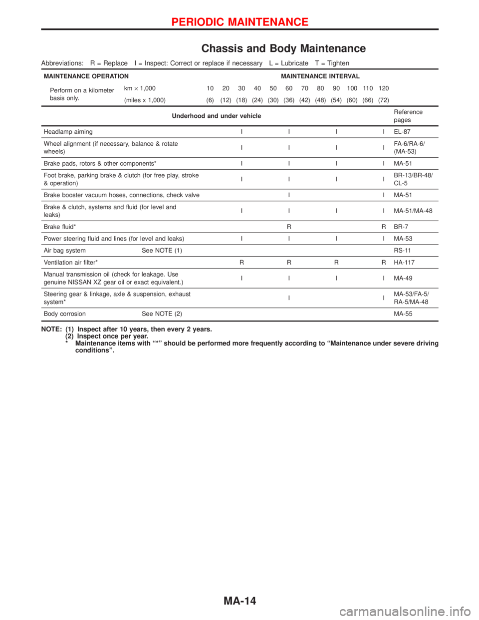
Chassis and Body Maintenance
Abbreviations: R = Replace I = Inspect: Correct or replace if necessary L = Lubricate T = Tighten
MAINTENANCE OPERATION MAINTENANCE INTERVAL
Perform on a kilometer
basis only.km×1,000 10 20 30 40 50 60 70 80 90 100 110 120
(miles x 1,000) (6) (12) (18) (24) (30) (36) (42) (48) (54) (60) (66) (72)
Underhood and under vehicleReference
pages
Headlamp aimingIIIIEL-87
Wheel alignment (if necessary, balance & rotate
wheels)IIIIFA-6/RA-6/
(MA-53)
Brake pads, rotors & other components*IIIIMA-51
Foot brake, parking brake & clutch (for free play, stroke
& operation)IIIIBR-13/BR-48/
CL-5
Brake booster vacuum hoses, connections, check valve I I MA-51
Brake & clutch, systems and fluid (for level and
leaks)IIIIMA-51/MA-48
Brake fluid*R R BR-7
Power steering fluid and lines (for level and leaks)IIIIMA-53
Air bag system See NOTE (1)RS-11
Ventilation air filter*RRRRHA-117
Manual transmission oil (check for leakage. Use
genuine NISSAN XZ gear oil or exact equivalent.)IIIIMA-49
Steering gear & linkage, axle & suspension, exhaust
system*IIMA-53/FA-5/
RA-5/MA-48
Body corrosion See NOTE (2)MA-55
NOTE: (1) Inspect after 10 years, then every 2 years.
(2) Inspect once per year.
* Maintenance items with“*”should be performed more frequently according to“Maintenance under severe driving
conditions”.
PERIODIC MAINTENANCE
MA-14
Page 2067 of 2267
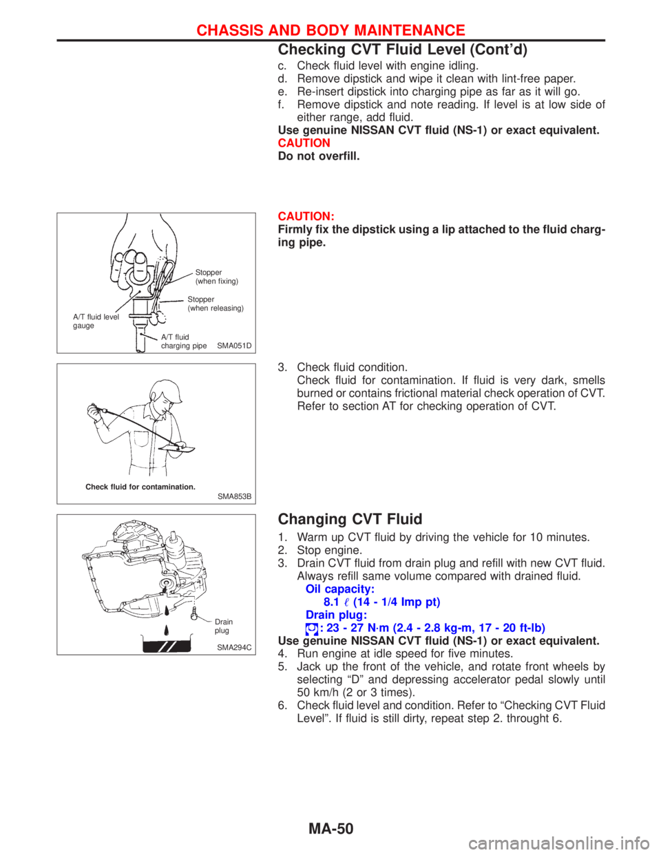
c. Check fluid level with engine idling.
d. Remove dipstick and wipe it clean with lint-free paper.
e. Re-insert dipstick into charging pipe as far as it will go.
f. Remove dipstick and note reading. If level is at low side of
either range, add fluid.
Use genuine NISSAN CVT fluid (NS-1) or exact equivalent.
CAUTION
Do not overfill.
CAUTION:
Firmly fix the dipstick using a lip attached to the fluid charg-
ing pipe.
3. Check fluid condition.
Check fluid for contamination. If fluid is very dark, smells
burned or contains frictional material check operation of CVT.
Refer to section AT for checking operation of CVT.
Changing CVT Fluid
1. Warm up CVT fluid by driving the vehicle for 10 minutes.
2. Stop engine.
3. Drain CVT fluid from drain plug and refill with new CVT fluid.
Always refill same volume compared with drained fluid.
Oil capacity:
8.1�(14 - 1/4 Imp pt)
Drain plug:
:23-27N·m (2.4 - 2.8 kg-m, 17 - 20 ft-lb)
Use genuine NISSAN CVT fluid (NS-1) or exact equivalent.
4. Run engine at idle speed for five minutes.
5. Jack up the front of the vehicle, and rotate front wheels by
selecting“D”and depressing accelerator pedal slowly until
50 km/h (2 or 3 times).
6. Check fluid level and condition. Refer to“Checking CVT Fluid
Level”. If fluid is still dirty, repeat step 2. throught 6.
SMA051D Stopper
(when fixing)
A/T fluid level
gauge
A/T fluid
charging pipeStopper
(when releasing)
SMA853B Check fluid for contamination.
SMA294C Drain
plug
CHASSIS AND BODY MAINTENANCE
Checking CVT Fluid Level (Cont’d)
MA-50
Page 2070 of 2267
Balancing Wheels
Wheel balance (maximum allowable unbalance):
10 g (0.35 oz) at rim flange.
Tire balance weight:
5 - 60 g (0.18 - 2.12 oz)
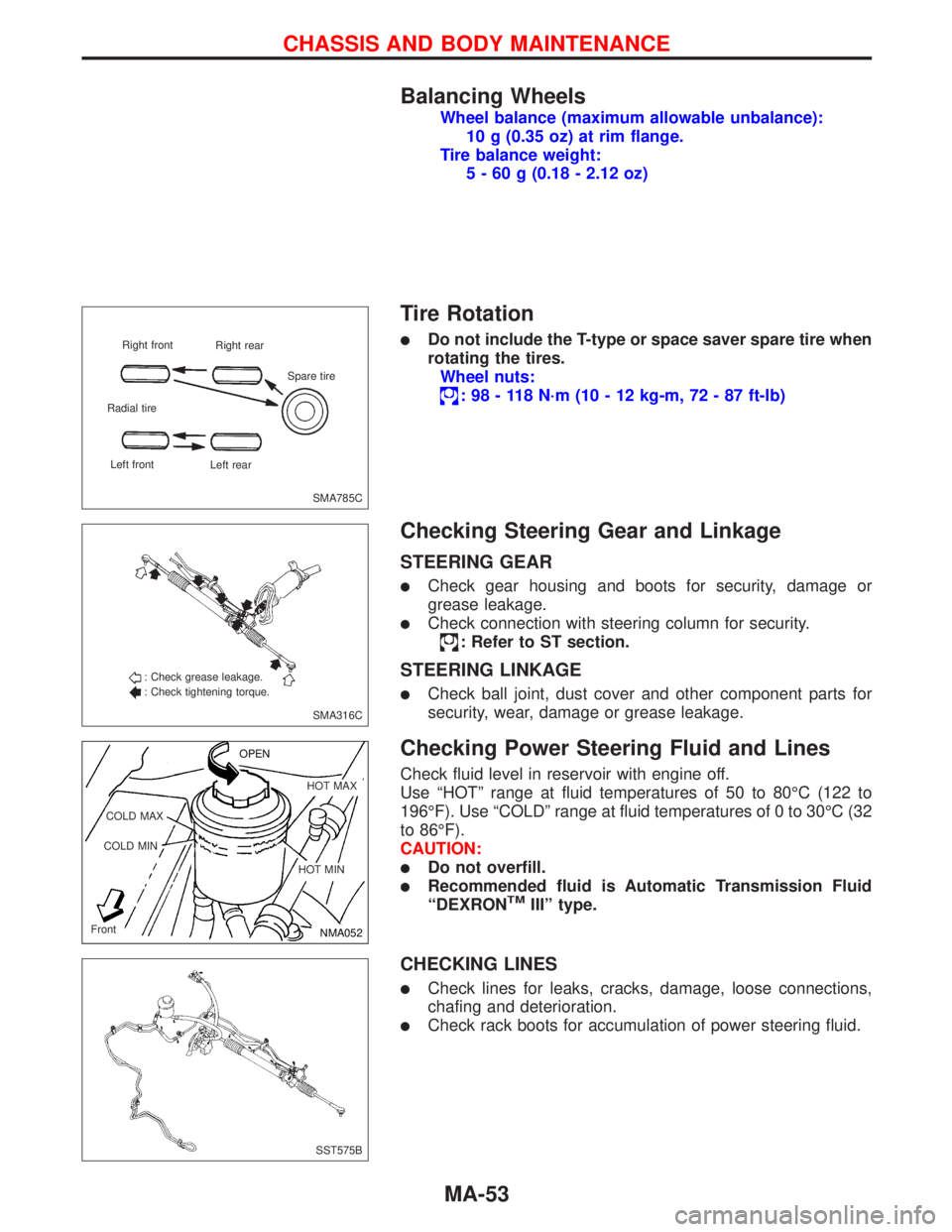
Tire Rotation
�Do not include the T-type or space saver spare tire when
rotating the tires.
Wheel nuts:
:98-118N·m (10 - 12 kg-m, 72 - 87 ft-lb)
Checking Steering Gear and Linkage
STEERING GEAR
�Check gear housing and boots for security, damage or
grease leakage.
�Check connection with steering column for security.
: Refer to ST section.
STEERING LINKAGE
�Check ball joint, dust cover and other component parts for
security, wear, damage or grease leakage.
Checking Power Steering Fluid and Lines
Check fluid level in reservoir with engine off.
Use“HOT”range at fluid temperatures of 50 to 80°C (122 to
196°F). Use“COLD”range at fluid temperatures of 0 to 30°C (32
to 86°F).
CAUTION:
�Do not overfill.
�Recommended fluid is Automatic Transmission Fluid
“DEXRONTMIII”type.
CHECKING LINES
�Check lines for leaks, cracks, damage, loose connections,
chafing and deterioration.
�Check rack boots for accumulation of power steering fluid.
SMA785C Right front
Right rear
Radial tire
Left front
Left rearSpare tire
SMA316C : Check grease leakage.
: Check tightening torque.
NMA052 OPEN
.HOT MAX
.HOT MIN COLD MAX
COLD MIN
Front
SST575B
CHASSIS AND BODY MAINTENANCE
MA-53
Page 2072 of 2267
Checking Body Corrosion
Visually check body panels for corrosion, paint damage (scratches, chipping, rubbing, etc.) or damage to
the anti-corrosion materials. In particular, check the following locations.
Hemmed panels
Hood front end, door lower end, trunk lid rear end, etc.
Panel joint
Side sill of rear fender and center pillar, rear wheel housing of rear fender, around strut tower in engine
compartment, etc.
Panel edge
Trunk lid opening, sunroof opening, fender wheel-arch flange, fuel filler lid flange, around holes in panel, etc.
Parts contact
Waist moulding, windshield moulding, bumper, etc.
Protectors
Damage or condition of mudguard, fender protector, chipping protector, etc.
Anti-corrosion materials
Damage or separation of anti-corrosion materials under the body.
Drain holes
Condition of drain holes at door and side sill.
When repairing corroded areas, refer to the Corrosion Repair Manual.
CHASSIS AND BODY MAINTENANCE
MA-55
Page 2076 of 2267
Chassis and Body Maintenance
Wheel balance
Wheel balance
(Maximum allowable unbalance
at rim flange) g (oz)10 (0.35)
Tire balance weight g (oz)5-60(0.18-2.12)
Spacing 5 (0.18)
SERVICE DATA AND SPECIFICATIONS (SDS)
MA-59
Page 2170 of 2267
REAR AXLE &
REAR SUSPENSION
SECTION
RA
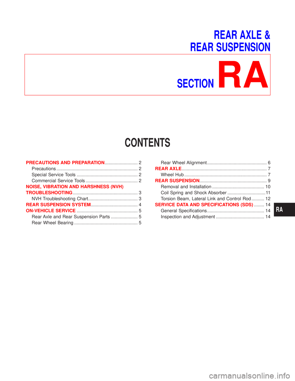
CONTENTS
PRECAUTIONS AND PREPARATION.......................... 2
Precautions ................................................................ 2
Special Service Tools ................................................ 2
Commercial Service Tools ......................................... 2
NOISE, VIBRATION AND HARSHNESS (NVH)
TROUBLESHOOTING................................................... 3
NVH Troubleshooting Chart....................................... 3
REAR SUSPENSION SYSTEM..................................... 4
ON-VEHICLE SERVICE................................................ 5
Rear Axle and Rear Suspension Parts ..................... 5
Rear Wheel Bearing .................................................. 5Rear Wheel Alignment ............................................... 6
REAR AXLE................................................................... 7
Wheel Hub ................................................................. 7
REAR SUSPENSION..................................................... 9
Removal and Installation ......................................... 10
Coil Spring and Shock Absorber .............................. 11
Torsion Beam, Lateral Link and Control Rod .......... 12
SERVICE DATA AND SPECIFICATIONS (SDS)........ 14
General Specifications ............................................. 14
Inspection and Adjustment ...................................... 14
RA
Page 2171 of 2267
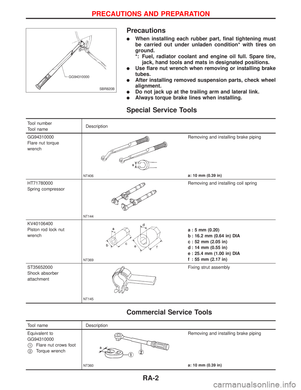
Precautions
lWhen installing each rubber part, final tightening must
be carried out under unladen condition* with tires on
ground.
*: Fuel, radiator coolant and engine oil full. Spare tire,
jack, hand tools and mats in designated positions.
lUse flare nut wrench when removing or installing brake
tubes.
lAfter installing removed suspension parts, check wheel
alignment.
lDo not jack up at the trailing arm and lateral link.
lAlways torque brake lines when installing.
Special Service Tools
Tool number
Tool nameDescription
GG94310000
Flare nut torque
wrench
NT406
Removing and installing brake piping
a: 10 mm (0.39 in)
HT71780000
Spring compressor
NT144
Removing and installing coil spring
KV40106400
Piston rod lock nut
wrench
NT369
a : 5 mm (0.20)
b : 16.2 mm (0.64 in) DIA
c : 52 mm (2.05 in)
d : 14 mm (0.55 in)
e : 25.4 mm (1.00 in) DIA
f : 55 mm (2.17 in)
ST35652000
Shock absorber
attachment
NT145
Fixing strut assembly
Commercial Service Tools
Tool name Description
Equivalent to
GG94310000
p1Flare nut crows foot
p2Torque wrench
NT360
Removing and installing brake piping
a: 10 mm (0.39 in)
SBR820B GG94310000
PRECAUTIONS AND PREPARATION
RA-2