1999 NISSAN PRIMERA wheel
[x] Cancel search: wheelPage 2191 of 2267
Precautions for SRS ªAIR BAGº and ªSEAT
BELT PRE-TENSIONERº Service
lDo not use electrical test equipment to check the SRS unless instructed to do in this Service Manual.
lBefore servicing the SRS, turn ignition switch ªOFFº, disconnect both battery cables and wait at least 3
minutes.
For approximately 3 minutes after the cables are removed, it is still possible for the air bag and seat belt
pre-tensioner to deploy. Therefore, do not work on any SRS connectors or wires until at least 3 minutes
have passed.
lDiagnosis sensor unit must always be installed with their arrow marks ªSº pointing towards the front of
the vehicle for proper operation. Also check diagnosis sensor unit for cracks, deformities or rust before
installation and replace as required.
lThe spiral cable must be aligned with the neutral position since its rotations are limited. Do not attempt
to turn steering wheel or column after removal of steering gear.
lHandle air bag module carefully. Always place driver's and passenger's air bag modules with the pad
side facing upward and place side air bag module (built-in type) standing with stud bolt side setting bot-
tom.
lConduct self-diagnosis to check entire SRS for proper function after replacing any components.
lAfter air bag inflates, the front instrument panel assembly should be replaced if damaged.
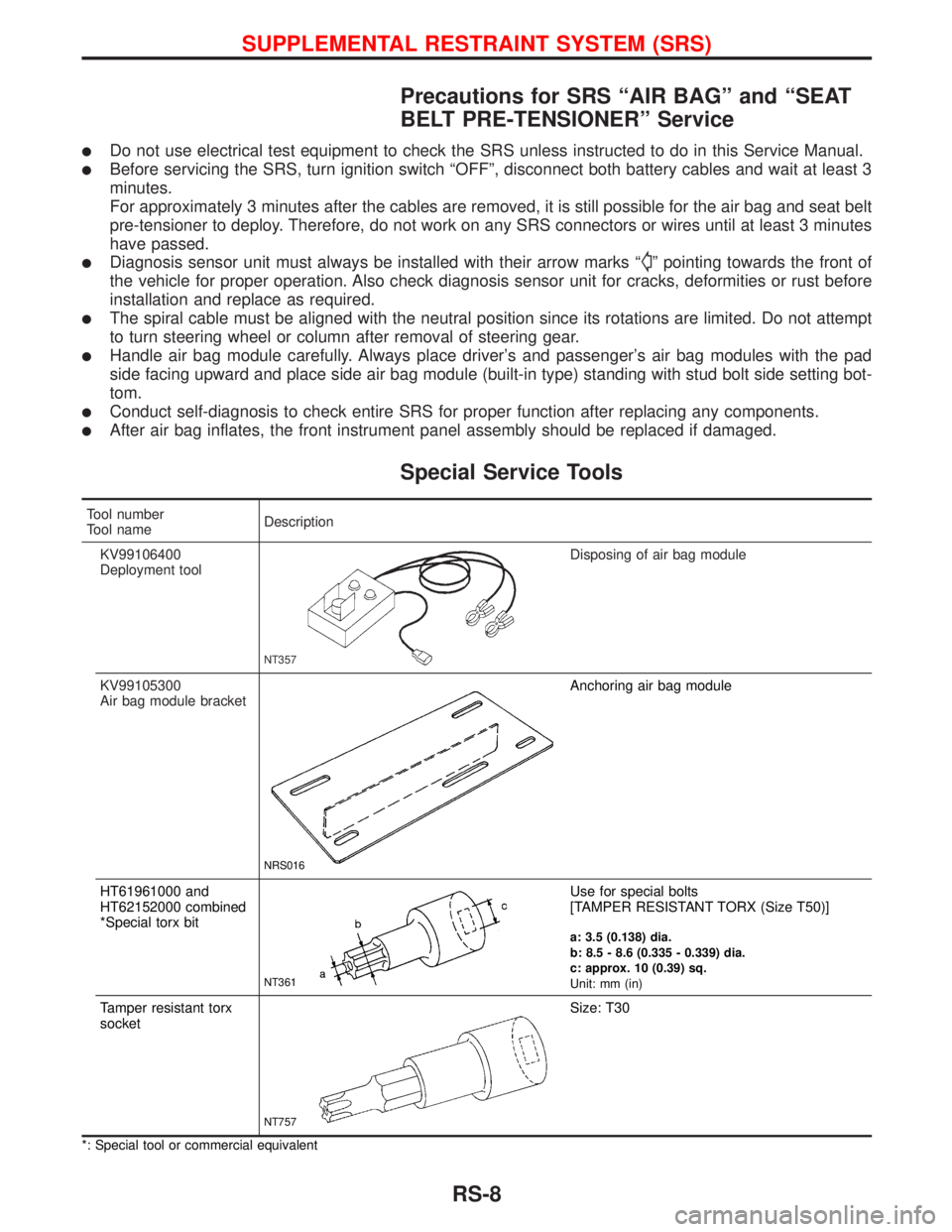
Special Service Tools
Tool number
Tool nameDescription
KV99106400
Deployment tool
NT357
Disposing of air bag module
KV99105300
Air bag module bracket
NRS016
Anchoring air bag module
HT61961000 and
HT62152000 combined
*Special torx bit
NT361
Use for special bolts
[TAMPER RESISTANT TORX (Size T50)]
a: 3.5 (0.138) dia.
b: 8.5 - 8.6 (0.335 - 0.339) dia.
c: approx. 10 (0.39) sq.
Unit: mm (in)
Tamper resistant torx
socket
NT757
Size: T30
*: Special tool or commercial equivalent
SUPPLEMENTAL RESTRAINT SYSTEM (SRS)
RS-8
Page 2195 of 2267
Maintenance Items
CAUTION:
Do not use electrical test equipment to check SRS circuit.
1. Check operation of ªAIR BAGº warning lamp.
After turning ignition key to ªONº position, the ªAIR BAGº
warning lamp illuminates. The ªAIR BAGº warning lamp will
go off after about 7 seconds if no malfunction is detected.
If any of the following warning lamp conditions occur, imme-
diately check the air bag system. Refer to ªSRS-Operation
Checkº for details. (RS-37)
lThe ªAIR BAGº warning lamp does not come on when the
ignition switch is turned ªONº.
lThe ªAIR BAGº warning lamp does not go off about 7 sec-
onds after the ignition switch is turned ªONº.
lThe ªAIR BAGº warning lamp blinks about 7 seconds after
the ignition switch is turned ªONº.
2. Visually check SRS components.
(1) Diagnosis sensor unit
lCheck diagnosis sensor unit and bracket for dents, cracks or
deformities.
lCheck connectors for damage, and terminals for deformities.
(2) Air bag module and steering wheel
lRemove air bag module from steering wheel, instrument
panel or seat back. Check harness cover and connectors for
damage, terminals for deformities, and harness for binding.
lInstall driver's air bag module to steering wheel to check fit
or alignment with the wheel.
lCheck steering wheel for excessive free play.
lInstall passenger's air bag module to instrument panel to
check fit or alignment with the instrument panel.
lInstall side air bag module to seatback to check fit and align-
ment with the seat.
(3) Spiral cable
lCheck spiral cable for dents, cracks, or deformities.
lCheck connectors and protective tape for damage.
lCheck steering wheel for noise, binding or heavy operation.
(4) Main harness, body harness and air bag harness
lCheck connectors for poor connections, damage, and termi-
nals for deformities.
lCheck harnesses for binding, chafing or cuts.
(5) Seat belt pre-tensioner
lCheck harness cover and connectors for damage, terminals
for deformities, and harness for binding.
lCheck belts for damage and anchors for loose mounting.
lCheck retractor for smooth operation.
lPerform self-diagnosis for seat belt pre-tensioner using ªAIR
BAGº warning lamp or CONSULT-II. Refer to ªSRS Operation
Checkº for details. (RS-37)
(6) Side airbag (Satellite) sensor
lCheck Side airbag (Satellite) sensor (including bracket por-
tion) for dents, cracks or deformities.
lCheck connectors for damage, and terminals for deformities.
SRS797-A
SUPPLEMENTAL RESTRAINT SYSTEM (SRS)
RS-12
Page 2198 of 2267
CAUTION:
lBefore servicing SRS, turn the ignition switch ªOFFº,
disconnect both battery cables and wait for at least 3
minutes.
lAlways work from the side of air bag module.
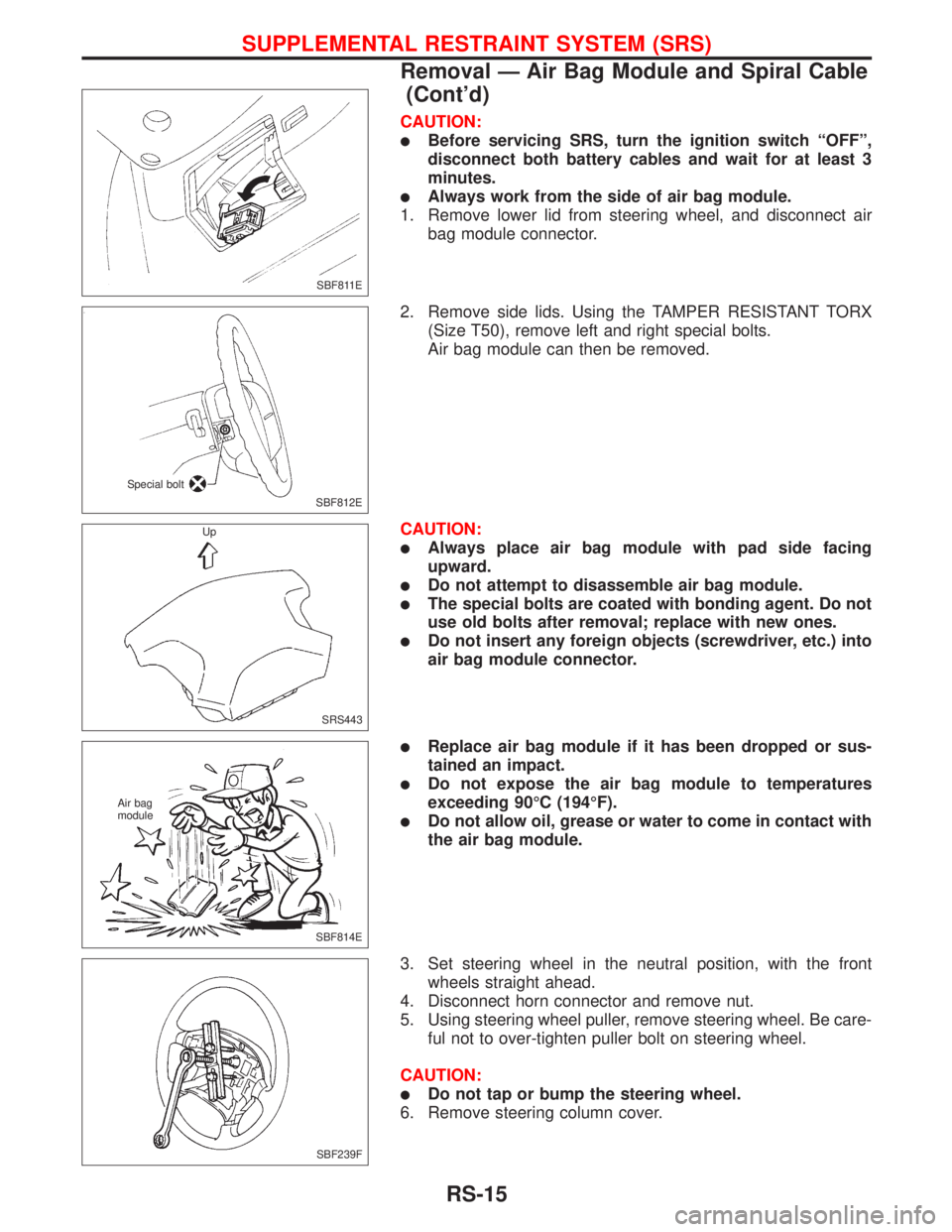
1. Remove lower lid from steering wheel, and disconnect air
bag module connector.
2. Remove side lids. Using the TAMPER RESISTANT TORX
(Size T50), remove left and right special bolts.
Air bag module can then be removed.
CAUTION:
lAlways place air bag module with pad side facing
upward.
lDo not attempt to disassemble air bag module.
lThe special bolts are coated with bonding agent. Do not
use old bolts after removal; replace with new ones.
lDo not insert any foreign objects (screwdriver, etc.) into
air bag module connector.
lReplace air bag module if it has been dropped or sus-
tained an impact.
lDo not expose the air bag module to temperatures
exceeding 90ÉC (194ÉF).
lDo not allow oil, grease or water to come in contact with
the air bag module.
3. Set steering wheel in the neutral position, with the front
wheels straight ahead.
4. Disconnect horn connector and remove nut.
5. Using steering wheel puller, remove steering wheel. Be care-
ful not to over-tighten puller bolt on steering wheel.
CAUTION:
lDo not tap or bump the steering wheel.
6. Remove steering column cover.
SBF811E
SBF812E Special bolt
SRS443 Up
SBF814E Air bag
module
SBF239F
SUPPLEMENTAL RESTRAINT SYSTEM (SRS)
Removal Ð Air Bag Module and Spiral Cable
(Cont'd)
RS-15
Page 2199 of 2267
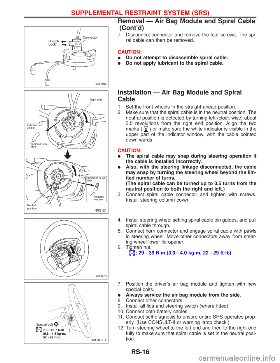
7. Disconnect connector and remove the four screws. The spi-
ral cable can then be removed.
CAUTION:
lDo not attempt to disassemble spiral cable.
lDo not apply lubricant to the spiral cable.
Installation Ð Air Bag Module and Spiral
Cable
1. Set the front wheels in the straight-ahead position.
2. Make sure that the spiral cable is in the neutral position. The
neutral position is detected by turning left (clock wise) about
3.5 revolutions from the right end position. Align the two
marks (
) or make sure the white indicator is visible in the
upper part of the indicator window, with the cable pointed
down wards.
CAUTION:
lThe spiral cable may snap during steering operation if
the cable is installed incorrectly.
lAlso, with the steering linkage disconnected, the cable
may snap by turning the steering wheel beyond the lim-
ited number of turns.
(The spiral cable can be turned up to 3.5 turns from the
neutral position to both the right and left.)
3. Connect spiral cable connector and tighten with screws.
Install steering column cover.
4. Install steering wheel setting spiral cable pin guides, and pull
spiral cable through.
5. Connect horn connector and engage spiral cable with pawls
in steering wheel. Move other connectors away from steer-
ing wheel lower lid opener.
6. Tighten nut.
: 29 - 39 N´m (3.0 - 4.0 kg-m, 22 - 29 ft-lb)
7. Position the driver's air bag module and tighten with new
special bolts.
lAlways service the air bag module from the side.
8. Connect other connectors.
9. Install all lids and steering switch (where fitted).
10. Connect both battery cables.
11. Conduct self-diagnosis to ensure entire SRS operates prop-
erly. (Use CONSULT-II or warning lamp check.)
12. Turn steering wheel to the left end and then to the right end
fully to make sure that spiral cable is set in the neutral posi-
tion.
SRS384 Unlock
LockConnector
NRS121
Neutral
positionRight end
Indicator not
visible
Indicator win-
dow
Indicator is vis-
ible
Indicator
window
SRS076
SBF812EA Special bolt
7.8 - 13.7 N´m
(0.8 - 1.4 kg-m,
57 - 99 ft-lb)
SUPPLEMENTAL RESTRAINT SYSTEM (SRS)
Removal Ð Air Bag Module and Spiral Cable
(Cont'd)
RS-16
Page 2240 of 2267
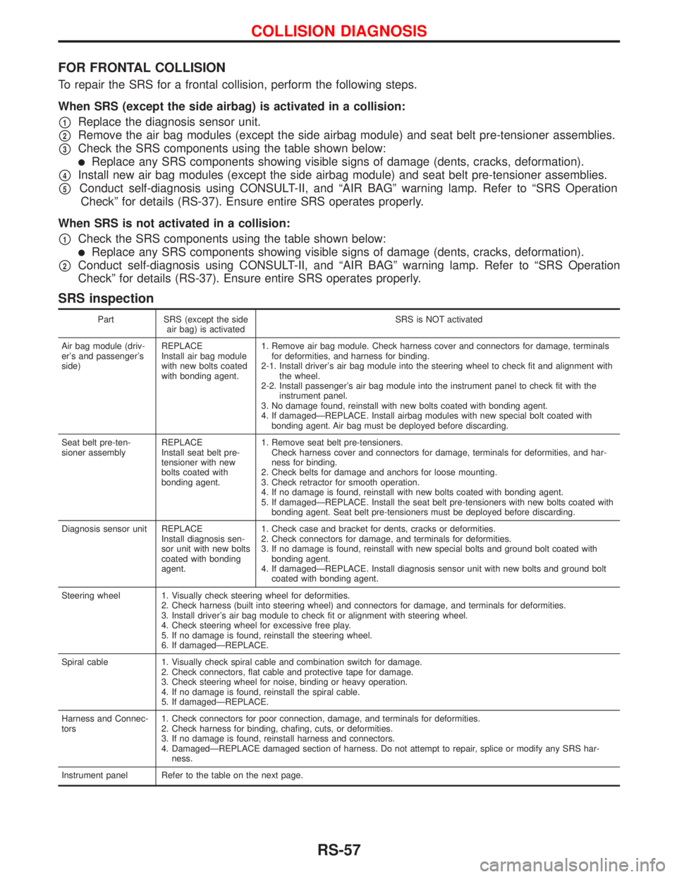
FOR FRONTAL COLLISION
To repair the SRS for a frontal collision, perform the following steps.
When SRS (except the side airbag) is activated in a collision:
p1Replace the diagnosis sensor unit.
p2Remove the air bag modules (except the side airbag module) and seat belt pre-tensioner assemblies.
p3Check the SRS components using the table shown below:
lReplace any SRS components showing visible signs of damage (dents, cracks, deformation).
p4Install new air bag modules (except the side airbag module) and seat belt pre-tensioner assemblies.
p5Conduct self-diagnosis using CONSULT-II, and ªAIR BAGº warning lamp. Refer to ªSRS Operation
Checkº for details (RS-37). Ensure entire SRS operates properly.
When SRS is not activated in a collision:
p1Check the SRS components using the table shown below:
lReplace any SRS components showing visible signs of damage (dents, cracks, deformation).
p2Conduct self-diagnosis using CONSULT-II, and ªAIR BAGº warning lamp. Refer to ªSRS Operation
Checkº for details (RS-37). Ensure entire SRS operates properly.
SRS inspection
Part SRS (except the side
air bag) is activatedSRS is NOT activated
Air bag module (driv-
er's and passenger's
side)REPLACE
Install air bag module
with new bolts coated
with bonding agent.1. Remove air bag module. Check harness cover and connectors for damage, terminals
for deformities, and harness for binding.
2-1. Install driver's air bag module into the steering wheel to check fit and alignment with
the wheel.
2-2. Install passenger's air bag module into the instrument panel to check fit with the
instrument panel.
3. No damage found, reinstall with new bolts coated with bonding agent.
4. If damagedÐREPLACE. Install airbag modules with new special bolt coated with
bonding agent. Air bag must be deployed before discarding.
Seat belt pre-ten-
sioner assemblyREPLACE
Install seat belt pre-
tensioner with new
bolts coated with
bonding agent.1. Remove seat belt pre-tensioners.
Check harness cover and connectors for damage, terminals for deformities, and har-
ness for binding.
2. Check belts for damage and anchors for loose mounting.
3. Check retractor for smooth operation.
4. If no damage is found, reinstall with new bolts coated with bonding agent.
5. If damagedÐREPLACE. Install the seat belt pre-tensioners with new bolts coated with
bonding agent. Seat belt pre-tensioners must be deployed before discarding.
Diagnosis sensor unit REPLACE
Install diagnosis sen-
sor unit with new bolts
coated with bonding
agent.1. Check case and bracket for dents, cracks or deformities.
2. Check connectors for damage, and terminals for deformities.
3. If no damage is found, reinstall with new special bolts and ground bolt coated with
bonding agent.
4. If damagedÐREPLACE. Install diagnosis sensor unit with new bolts and ground bolt
coated with bonding agent.
Steering wheel 1. Visually check steering wheel for deformities.
2. Check harness (built into steering wheel) and connectors for damage, and terminals for deformities.
3. Install driver's air bag module to check fit or alignment with steering wheel.
4. Check steering wheel for excessive free play.
5. If no damage is found, reinstall the steering wheel.
6. If damagedÐREPLACE.
Spiral cable 1. Visually check spiral cable and combination switch for damage.
2. Check connectors, flat cable and protective tape for damage.
3. Check steering wheel for noise, binding or heavy operation.
4. If no damage is found, reinstall the spiral cable.
5. If damagedÐREPLACE.
Harness and Connec-
tors1. Check connectors for poor connection, damage, and terminals for deformities.
2. Check harness for binding, chafing, cuts, or deformities.
3. If no damage is found, reinstall harness and connectors.
4. DamagedÐREPLACE damaged section of harness. Do not attempt to repair, splice or modify any SRS har-
ness.
Instrument panel Refer to the table on the next page.
COLLISION DIAGNOSIS
RS-57
Page 2244 of 2267
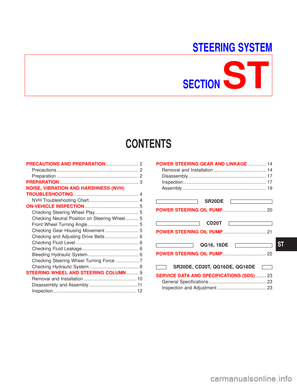
STEERING SYSTEM
SECTION
ST
CONTENTS
PRECAUTIONS AND PREPARATION.......................... 2
Precautions ................................................................ 2
Preparation ................................................................ 2
PREPARATION.............................................................. 3
NOISE, VIBRATION AND HARSHNESS (NVH)
TROUBLESHOOTING................................................... 4
NVH Troubleshooting Chart....................................... 4
ON-VEHICLE INSPECTION.......................................... 5
Checking Steering Wheel Play .................................. 5
Checking Neutral Position on Steering Wheel .......... 5
Front Wheel Turning Angle ........................................ 5
Checking Gear Housing Movement .......................... 5
Checking and Adjusting Drive Belts .......................... 6
Checking Fluid Level ................................................. 6
Checking Fluid Leakage ............................................ 6
Bleeding Hydraulic System........................................ 6
Checking Steering Wheel Turning Force .................. 7
Checking Hydraulic System....................................... 8
STEERING WHEEL AND STEERING COLUMN.......... 9
Removal and Installation ......................................... 10
Disassembly and Assembly ...................................... 11
Inspection................................................................. 12POWER STEERING GEAR AND LINKAGE.............. 14
Removal and Installation ......................................... 14
Disassembly............................................................. 17
Inspection................................................................. 17
Assembly ................................................................. 19
SR20DE
POWER STEERING OIL PUMP.................................. 20
CD20T
POWER STEERING OIL PUMP.................................. 21
QG16, 18DE
POWER STEERING OIL PUMP.................................. 22
SR20DE, CD20T, QG16DE, QG18DE
SERVICE DATA AND SPECIFICATIONS (SDS)........ 23
General Specifications ............................................. 23
Inspection and Adjustment ...................................... 23
ST
Page 2245 of 2267
Precautions
Supplemental Restraint System (SRS) ªAIR BAGº
and ªSEAT BELT PRE-TENSIONERº
The Supplemental Restraint System ªAir Bagº and ªSeat Belt Pre-tensionerº, used along with a seat belt,
help to reduce the risk or severity of injury to the driver and front passenger in a frontal collision. The
Supplemental Restraint System consists of air bag modules (located in the center of the steering wheel and
on the instrument panel on the passenger side), seat belt pre-tensioners, a diagnosis sensor unit, warning
lamp, wiring harness and spiral cable.
If the vehicle is equipped with side air bag as the Supplemental Restraint System, the side air bag used along
with the seat belt helps to reduce the risk or severity of injury to the driver and front passenger in a side
collision. The side air bag consists of air bag modules (located in the outer side of front seats), satellite
sensor, diagnosis sensor unit (which is one of components of air bags for a frontal collision), wiring harness,
warning lamp (which is one of components of air bags for a frontal collision).
WARNING:
lTo avoid rendering the SRS inoperative, which could increase the risk of personal injury or death
(in the event of a collision which would result in air bag inflation), all maintenance must be per-
formed by an authorized NISSAN dealer.
lImproper maintenance, including incorrect removal and installation of the SRS, can lead to per-
sonal injury caused by unintentional activation of the system.
lDo not use electrical test equipment on any circuit related to the SRS unless instructed to do so
in this Service Manual. SRS wiring harnesses are covered with yellow insulation (either just
before the harness connectors or for the complete harness), for easy identification.
STEERING SYSTEM
lBefore disassembly, thoroughly clean the outside of the unit.
lDisassembly should be done in a clean work area. It is important to prevent the internal parts
from becoming contaminated by dirt or other foreign matter.
lWhen disassembling parts, be sure to place them in order on a part rack so they can be rein-
stalled in their correct positions.
lOnly use nylon cloths or paper towels to clean parts. Do not use rags or other materials contain-
ing lint. Residual debris may damage the system.
lBefore inspection or reassembly, carefully clean all parts with a general purpose, non-flammable
solvent.
lBefore assembly, apply a coat of recommended ATF* to hydraulic parts. Vaseline may be applied
to O-rings and seals. Do not use any grease.
lReplace all gaskets, seals and O-rings. Avoid damaging O-rings, seals and gaskets during instal-
lation. Perform functional tests whenever designated.
*: Automatic transmission fluid
Preparation
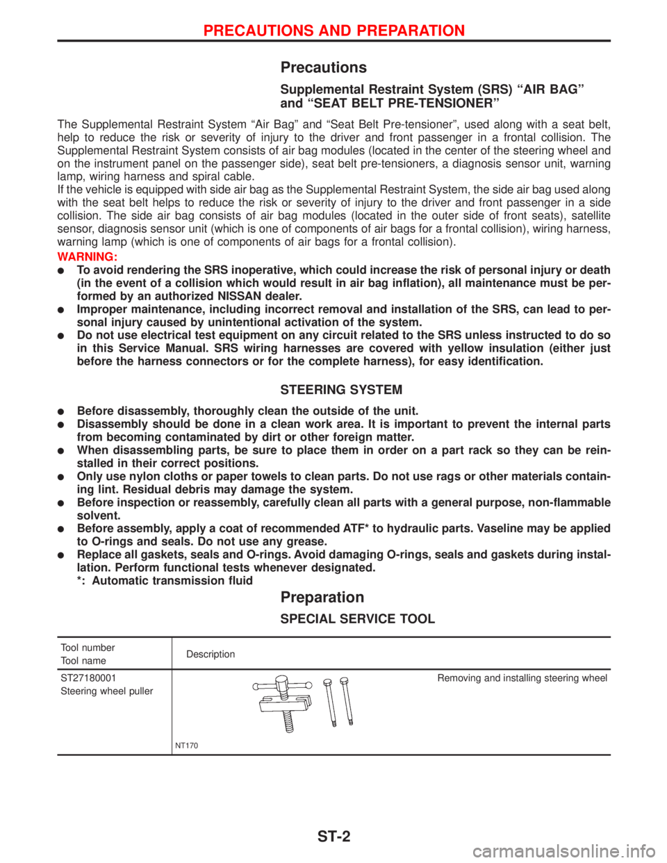
SPECIAL SERVICE TOOL
Tool number
Tool nameDescription
ST27180001
Steering wheel puller
NT170
Removing and installing steering wheel
PRECAUTIONS AND PREPARATION
ST-2
Page 2247 of 2267
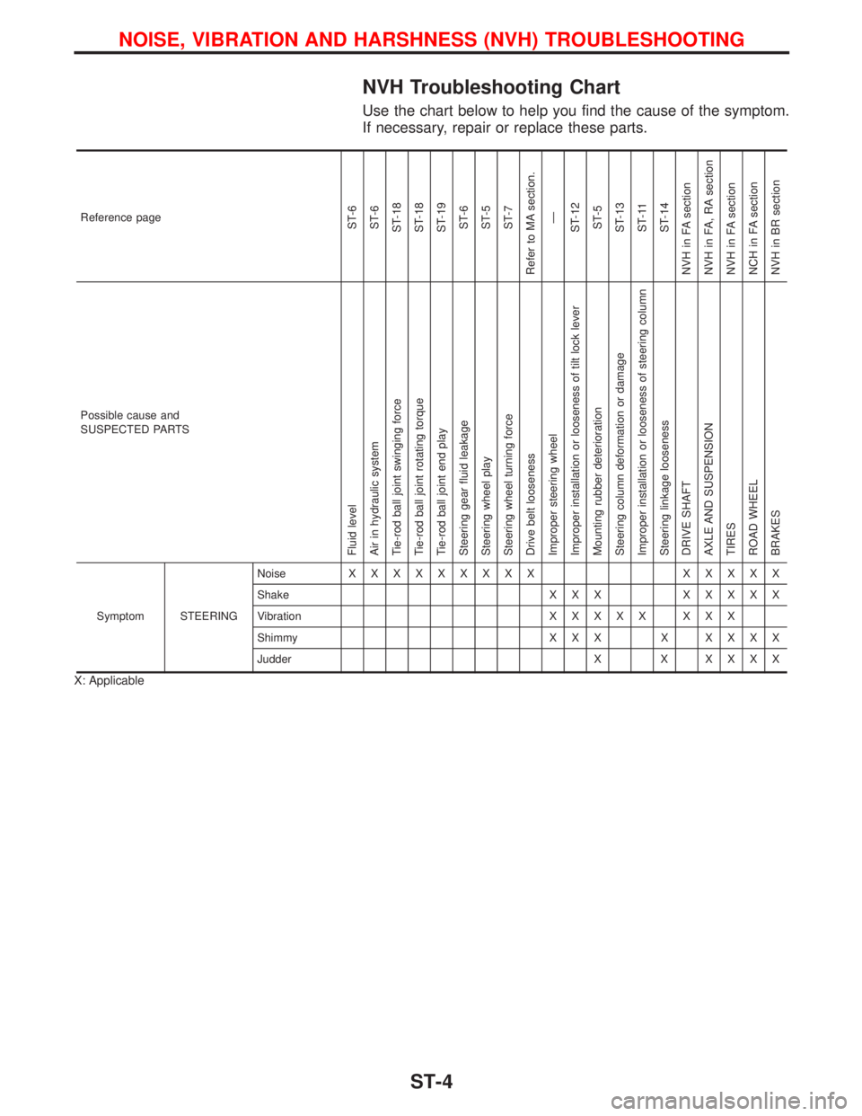
NVH Troubleshooting Chart
Use the chart below to help you find the cause of the symptom.
If necessary, repair or replace these parts.
Reference pageST-6
ST-6
ST-18
ST-18
ST-19
ST-6
ST-5
ST-7
Refer to MA section.
Ð
ST-12
ST-5
ST-13
ST-11
ST-14
NVH in FA section
NVH in FA, RA section
NVH in FA section
NCH in FA section
NVH in BR section
Possible cause and
SUSPECTED PARTS
Fluid level
Air in hydraulic system
Tie-rod ball joint swinging force
Tie-rod ball joint rotating torque
Tie-rod ball joint end play
Steering gear fluid leakage
Steering wheel play
Steering wheel turning force
Drive belt looseness
Improper steering wheel
Improper installation or looseness of tilt lock lever
Mounting rubber deterioration
Steering column deformation or damage
Improper installation or looseness of steering column
Steering linkage looseness
DRIVE SHAFT
AXLE AND SUSPENSION
TIRES
ROAD WHEEL
BRAKES
Symptom STEERINGNoiseXXXXXXXXX XXXXX
Shake X X XXXXXX
VibrationXXXXX XXX
Shimmy X X X XXXXX
Judder X XXXXX
X: Applicable
NOISE, VIBRATION AND HARSHNESS (NVH) TROUBLESHOOTING
ST-4