Page 1034 of 2267
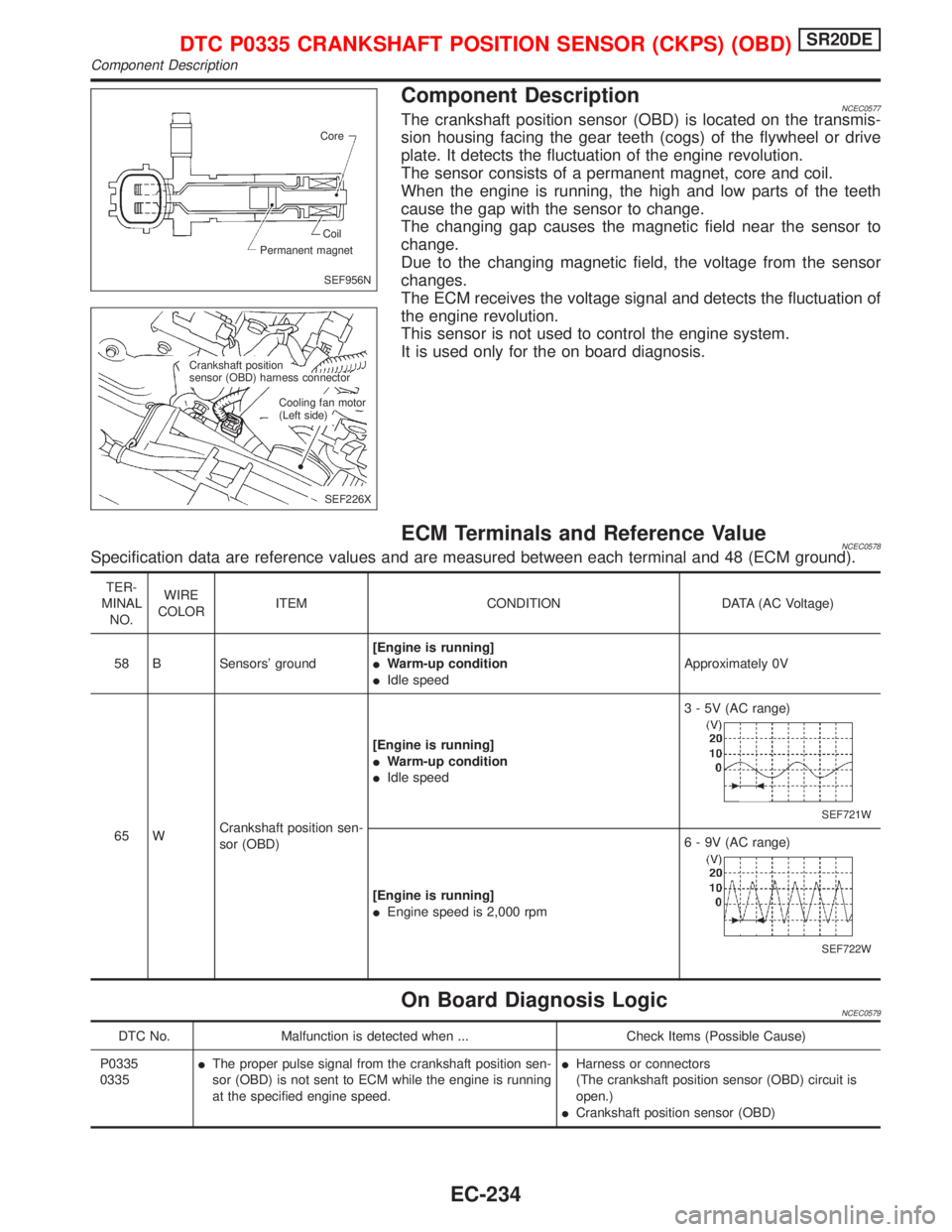
Component DescriptionNCEC0577The crankshaft position sensor (OBD) is located on the transmis-
sion housing facing the gear teeth (cogs) of the flywheel or drive
plate. It detects the fluctuation of the engine revolution.
The sensor consists of a permanent magnet, core and coil.
When the engine is running, the high and low parts of the teeth
cause the gap with the sensor to change.
The changing gap causes the magnetic field near the sensor to
change.
Due to the changing magnetic field, the voltage from the sensor
changes.
The ECM receives the voltage signal and detects the fluctuation of
the engine revolution.
This sensor is not used to control the engine system.
It is used only for the on board diagnosis.
ECM Terminals and Reference ValueNCEC0578Specification data are reference values and are measured between each terminal and 48 (ECM ground).
TER-
MINAL
NO.WIRE
COLORITEM CONDITION DATA (AC Voltage)
58 B Sensors' ground[Engine is running]
IWarm-up condition
IIdle speedApproximately 0V
65 WCrankshaft position sen-
sor (OBD)[Engine is running]
IWarm-up condition
IIdle speed3 - 5V (AC range)
SEF721W
[Engine is running]
IEngine speed is 2,000 rpm6 - 9V (AC range)
SEF722W
On Board Diagnosis LogicNCEC0579
DTC No. Malfunction is detected when ... Check Items (Possible Cause)
P0335
0335IThe proper pulse signal from the crankshaft position sen-
sor (OBD) is not sent to ECM while the engine is running
at the specified engine speed.IHarness or connectors
(The crankshaft position sensor (OBD) circuit is
open.)
ICrankshaft position sensor (OBD)
SEF956N Core
Permanent magnetCoil
SEF226X Crankshaft position
sensor (OBD) harness connector
Cooling fan motor
(Left side)
DTC P0335 CRANKSHAFT POSITION SENSOR (CKPS) (OBD)SR20DE
Component Description
EC-234
Page 1055 of 2267
Component DescriptionNCEC0272MODELS WITH VEHICLE SPEED SENSOR
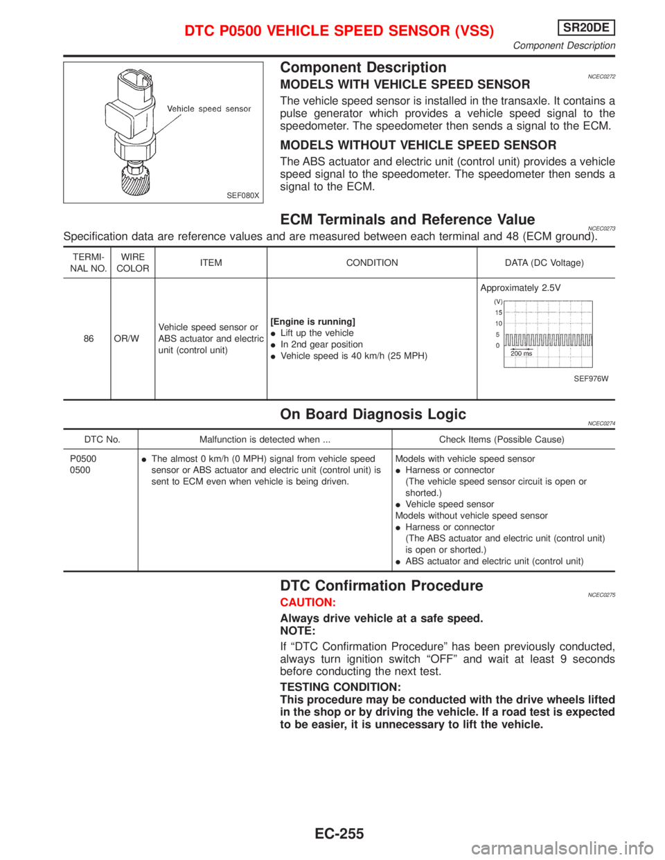
The vehicle speed sensor is installed in the transaxle. It contains a
pulse generator which provides a vehicle speed signal to the
speedometer. The speedometer then sends a signal to the ECM.
MODELS WITHOUT VEHICLE SPEED SENSOR
The ABS actuator and electric unit (control unit) provides a vehicle
speed signal to the speedometer. The speedometer then sends a
signal to the ECM.
ECM Terminals and Reference ValueNCEC0273Specification data are reference values and are measured between each terminal and 48 (ECM ground).
TERMI-
NAL NO.WIRE
COLORITEM CONDITION DATA (DC Voltage)
86 OR/WVehicle speed sensor or
ABS actuator and electric
unit (control unit)[Engine is running]
ILift up the vehicle
IIn 2nd gear position
IVehicle speed is 40 km/h (25 MPH)Approximately 2.5V
SEF976W
On Board Diagnosis LogicNCEC0274
DTC No. Malfunction is detected when ... Check Items (Possible Cause)
P0500
0500IThe almost 0 km/h (0 MPH) signal from vehicle speed
sensor or ABS actuator and electric unit (control unit) is
sent to ECM even when vehicle is being driven.Models with vehicle speed sensor
IHarness or connector
(The vehicle speed sensor circuit is open or
shorted.)
IVehicle speed sensor
Models without vehicle speed sensor
IHarness or connector
(The ABS actuator and electric unit (control unit)
is open or shorted.)
IABS actuator and electric unit (control unit)
DTC Confirmation ProcedureNCEC0275CAUTION:
Always drive vehicle at a safe speed.
NOTE:
If ªDTC Confirmation Procedureº has been previously conducted,
always turn ignition switch ªOFFº and wait at least 9 seconds
before conducting the next test.
TESTING CONDITION:
This procedure may be conducted with the drive wheels lifted
in the shop or by driving the vehicle. If a road test is expected
to be easier, it is unnecessary to lift the vehicle.
SEF080X
DTC P0500 VEHICLE SPEED SENSOR (VSS)SR20DE
Component Description
EC-255
Page 1056 of 2267
With CONSULT-II
1) Start engine
2) Read vehicle speed sensor signal in ªDATA MONITORº mode
with CONSULT-II. The vehicle speed on CONSULT-II should
exceed 10 km/h (6 MPH) when rotating wheels with suitable
gear position.
3) If NG, go to ªDiagnostic Procedureº, EC-SR-260.
If OK, go to following step.
4) Select ªDATA MONITORº mode with CONSULT-II.
5) Warm engine up to normal operating temperature.
6) Maintain the following conditions for at least 10 consecutive
seconds.
ENG SPEED 2,000 - 3,000 rpm (CVT)
2,700 - 3,000 rpm (M/T)
COOLAN TEMP/S More than 70ÉC (158ÉF)
B/FUEL SCHDL 5 - 8.5 msec (CVT)
5 - 14.5 msec (M/T)
Selector lever Suitable position
PW/ST SIGNAL OFF
7) If 1st trip DTC is detected, go to ªDiagnostic Procedureº, EC-
SR-260.
With GST
Follow the procedure ªWith CONSULT-IIº above.
NEF112A
DTC P0500 VEHICLE SPEED SENSOR (VSS)SR20DE
DTC Confirmation Procedure (Cont'd)
EC-256
Page 1067 of 2267
4 CHECK AIR CONTROL VALVE (POWER STEERING) OPERATION-I
1. Reconnect the ECM harness connector and IACV-AAC valve harness connector.
2. Disconnect vacuum hose connected to air control valve (Power steering) at intake air duct.
3. Start and let it idle.
4. Check vacuum hose for vacuum existence.
SEF969X
Vacuum slightly exists or does not exist.
OK or NG
OK©GO TO 5.
NG©Replace air control valve (Power steering).
5 CHECK AIR CONTROL VALVE (POWER STEERING) OPERATION-II
Check the vacuum hose for vacuum existence when steering wheel is turned.
SEF969X
Vacuum should exist.
OK or NG
OK©GO TO 8.
NG©GO TO 6.
DTC P0505 IDLE AIR CONTROL VALVE (IACV) Ð
AUXILIARY AIR CONTROL (AAC) VALVESR20DE
Diagnostic Procedure (Cont'd)
EC-267
Page 1090 of 2267
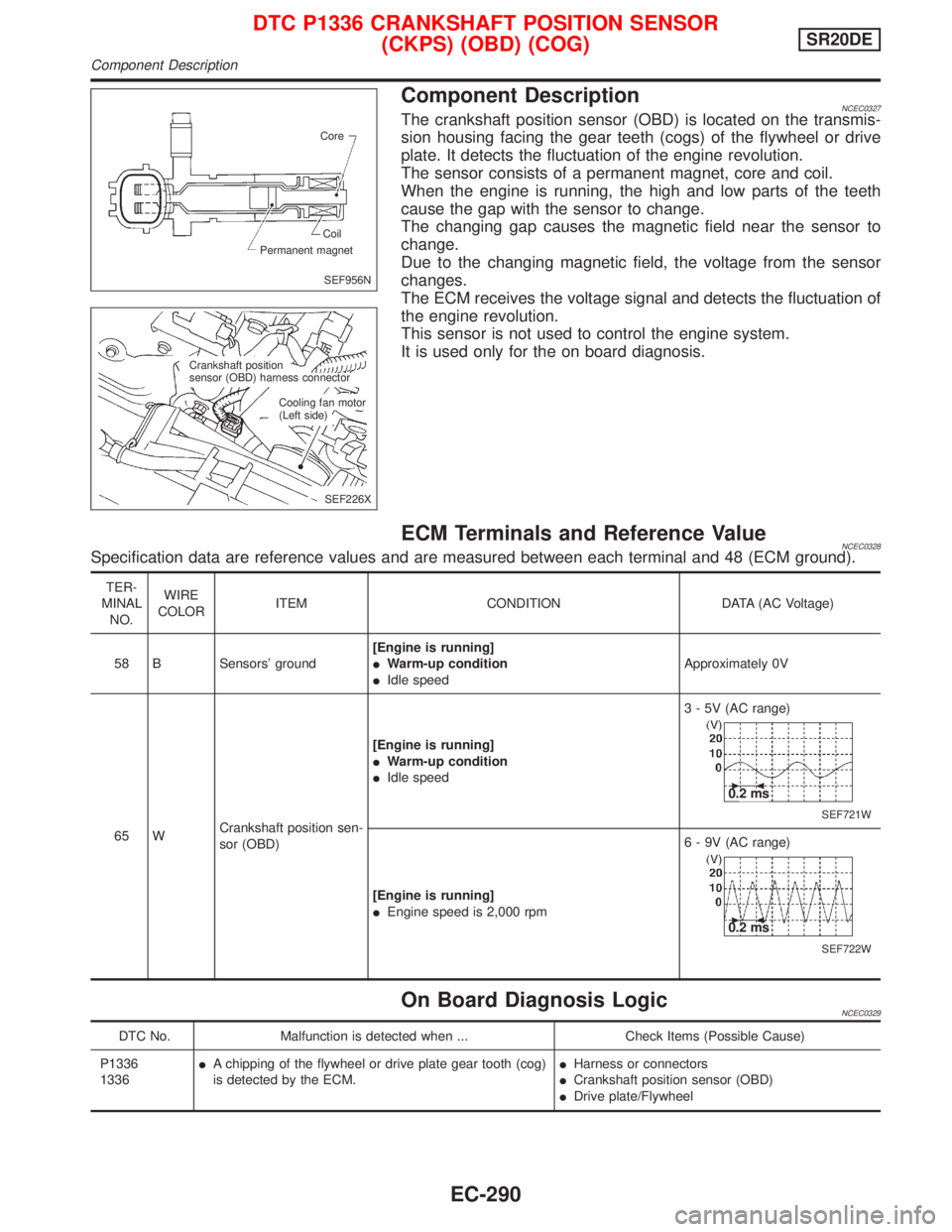
Component DescriptionNCEC0327The crankshaft position sensor (OBD) is located on the transmis-
sion housing facing the gear teeth (cogs) of the flywheel or drive
plate. It detects the fluctuation of the engine revolution.
The sensor consists of a permanent magnet, core and coil.
When the engine is running, the high and low parts of the teeth
cause the gap with the sensor to change.
The changing gap causes the magnetic field near the sensor to
change.
Due to the changing magnetic field, the voltage from the sensor
changes.
The ECM receives the voltage signal and detects the fluctuation of
the engine revolution.
This sensor is not used to control the engine system.
It is used only for the on board diagnosis.
ECM Terminals and Reference ValueNCEC0328Specification data are reference values and are measured between each terminal and 48 (ECM ground).
TER-
MINAL
NO.WIRE
COLORITEM CONDITION DATA (AC Voltage)
58 B Sensors' ground[Engine is running]
IWarm-up condition
IIdle speedApproximately 0V
65 WCrankshaft position sen-
sor (OBD)[Engine is running]
IWarm-up condition
IIdle speed3 - 5V (AC range)
SEF721W
0.2 ms
[Engine is running]
IEngine speed is 2,000 rpm6 - 9V (AC range)
SEF722W
0.2 ms
On Board Diagnosis LogicNCEC0329
DTC No. Malfunction is detected when ... Check Items (Possible Cause)
P1336
1336IA chipping of the flywheel or drive plate gear tooth (cog)
is detected by the ECM.IHarness or connectors
ICrankshaft position sensor (OBD)
IDrive plate/Flywheel
SEF956N Core
Permanent magnetCoil
SEF226X Crankshaft position
sensor (OBD) harness connector
Cooling fan motor
(Left side)
DTC P1336 CRANKSHAFT POSITION SENSOR
(CKPS) (OBD) (COG)SR20DE
Component Description
EC-290
Page 1094 of 2267
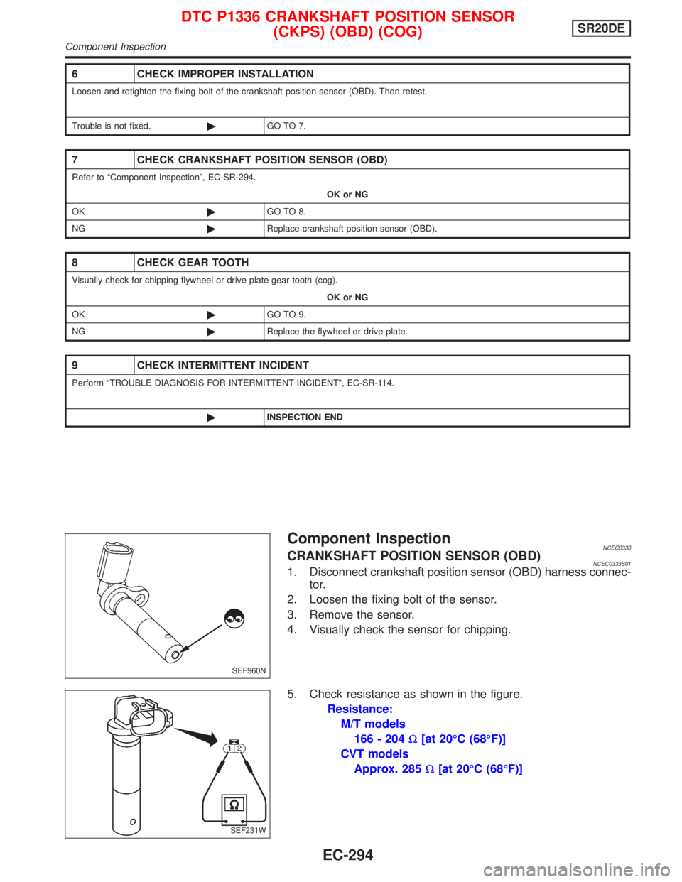
Component InspectionNCEC0333CRANKSHAFT POSITION SENSOR (OBD)NCEC0333S011. Disconnect crankshaft position sensor (OBD) harness connec-
tor.
2. Loosen the fixing bolt of the sensor.
3. Remove the sensor.
4. Visually check the sensor for chipping.
5. Check resistance as shown in the figure.
Resistance:
M/T models
166 - 204W[at 20ÉC (68ÉF)]
CVT models
Approx. 285W[at 20ÉC (68ÉF)]
6 CHECK IMPROPER INSTALLATION
Loosen and retighten the fixing bolt of the crankshaft position sensor (OBD). Then retest.
Trouble is not fixed.©GO TO 7.
7 CHECK CRANKSHAFT POSITION SENSOR (OBD)
Refer to ªComponent Inspectionº, EC-SR-294.
OK or NG
OK©GO TO 8.
NG©Replace crankshaft position sensor (OBD).
8 CHECK GEAR TOOTH
Visually check for chipping flywheel or drive plate gear tooth (cog).
OK or NG
OK©GO TO 9.
NG©Replace the flywheel or drive plate.
9 CHECK INTERMITTENT INCIDENT
Perform ªTROUBLE DIAGNOSIS FOR INTERMITTENT INCIDENTº, EC-SR-114.
©INSPECTION END
SEF960N
SEF231W
DTC P1336 CRANKSHAFT POSITION SENSOR
(CKPS) (OBD) (COG)SR20DE
Component Inspection
EC-294
Page 1121 of 2267
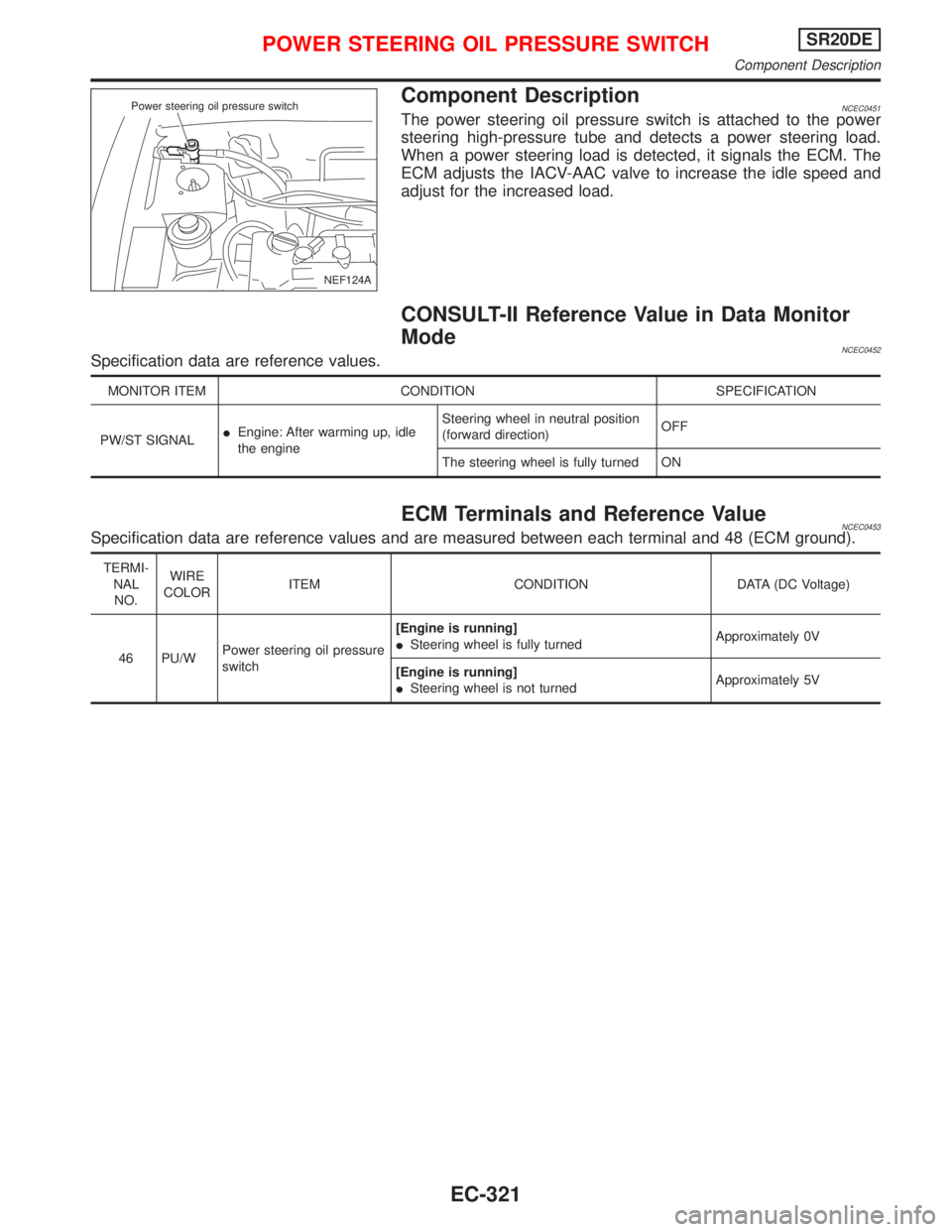
Component DescriptionNCEC0451The power steering oil pressure switch is attached to the power
steering high-pressure tube and detects a power steering load.
When a power steering load is detected, it signals the ECM. The
ECM adjusts the IACV-AAC valve to increase the idle speed and
adjust for the increased load.
CONSULT-II Reference Value in Data Monitor
Mode
NCEC0452Specification data are reference values.
MONITOR ITEM CONDITION SPECIFICATION
PW/ST SIGNALIEngine: After warming up, idle
the engineSteering wheel in neutral position
(forward direction)OFF
The steering wheel is fully turned ON
ECM Terminals and Reference ValueNCEC0453Specification data are reference values and are measured between each terminal and 48 (ECM ground).
TERMI-
NAL
NO.WIRE
COLORITEM CONDITION DATA (DC Voltage)
46 PU/WPower steering oil pressure
switch[Engine is running]
ISteering wheel is fully turnedApproximately 0V
[Engine is running]
ISteering wheel is not turnedApproximately 5V
NEF124A Power steering oil pressure switch
POWER STEERING OIL PRESSURE SWITCHSR20DE
Component Description
EC-321
Page 1123 of 2267
Diagnostic Procedure=NCEC0454
1 INSPECTION START
Do you have CONSULT-II?
YesorNo
Ye s©GO TO 2.
No©GO TO 3.
2 CHECK OVERALL FUNCTION
With CONSULT-II
1. Start engine.
2. Check ªPW/ST SIGNALº in ªDATA MONITORº mode with CONSULT-II under the following conditions.
PEF591I
MTBL0141
OK or NG
OK©INSPECTION END
NG©GO TO 4.
3 CHECK OVERALL FUNCTION
Without CONSULT-II
1. Start engine.
2. Check voltage between ECM terminal 46 and ground under the following conditions.
SEF148X
MTBL0142
OK or NG
OK©INSPECTION END
NG©GO TO 4.
Steering is in neutral positionOFF
Steering is turnedON
Condition Voltage
When steering wheel is turned quicklyApproximately 0V
Except aboveApproximately 5V
CONNECT
POWER STEERING OIL PRESSURE SWITCHSR20DE
Diagnostic Procedure
EC-323