1999 NISSAN PRIMERA wheel
[x] Cancel search: wheelPage 284 of 2267
INSPECITON
Pedal stroke
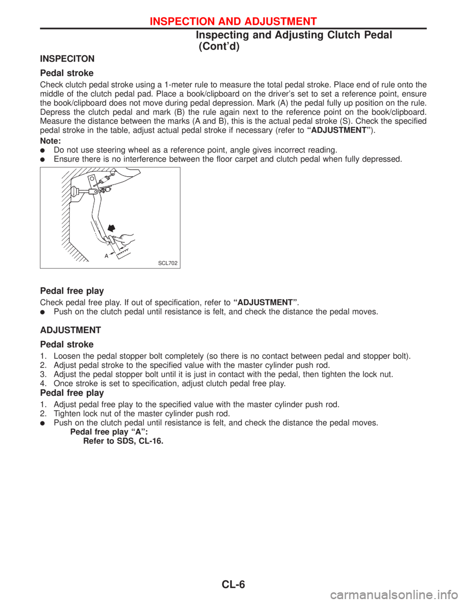
Check clutch pedal stroke using a 1-meter rule to measure the total pedal stroke. Place end of rule onto the
middle of the clutch pedal pad. Place a book/clipboard on the driver's set to set a reference point, ensure
the book/clipboard does not move during pedal depression. Mark (A) the pedal fully up position on the rule.
Depress the clutch pedal and mark (B) the rule again next to the reference point on the book/clipboard.
Measure the distance between the marks (A and B), this is the actual pedal stroke (S). Check the specified
pedal stroke in the table, adjust actual pedal stroke if necessary (refer toªADJUSTMENTº).
Note:
lDo not use steering wheel as a reference point, angle gives incorrect reading.
lEnsure there is no interference between the floor carpet and clutch pedal when fully depressed.
Pedal free play
Check pedal free play. If out of specification, refer toªADJUSTMENTº.
lPush on the clutch pedal until resistance is felt, and check the distance the pedal moves.
ADJUSTMENT
Pedal stroke
1. Loosen the pedal stopper bolt completely (so there is no contact between pedal and stopper bolt).
2. Adjust pedal stroke to the specified value with the master cylinder push rod.
3. Adjust the pedal stopper bolt until it is just in contact with the pedal, then tighten the lock nut.
4. Once stroke is set to specification, adjust clutch pedal free play.
Pedal free play
1. Adjust pedal free play to the specified value with the master cylinder push rod.
2. Tighten lock nut of the master cylinder push rod.
lPush on the clutch pedal until resistance is felt, and check the distance the pedal moves.
Pedal free play ªAº:
Refer to SDS, CL-16.
SCL702
INSPECTION AND ADJUSTMENT
Inspecting and Adjusting Clutch Pedal
(Cont'd)
CL-6
Page 289 of 2267
REMOVAL AND INSTALLATION
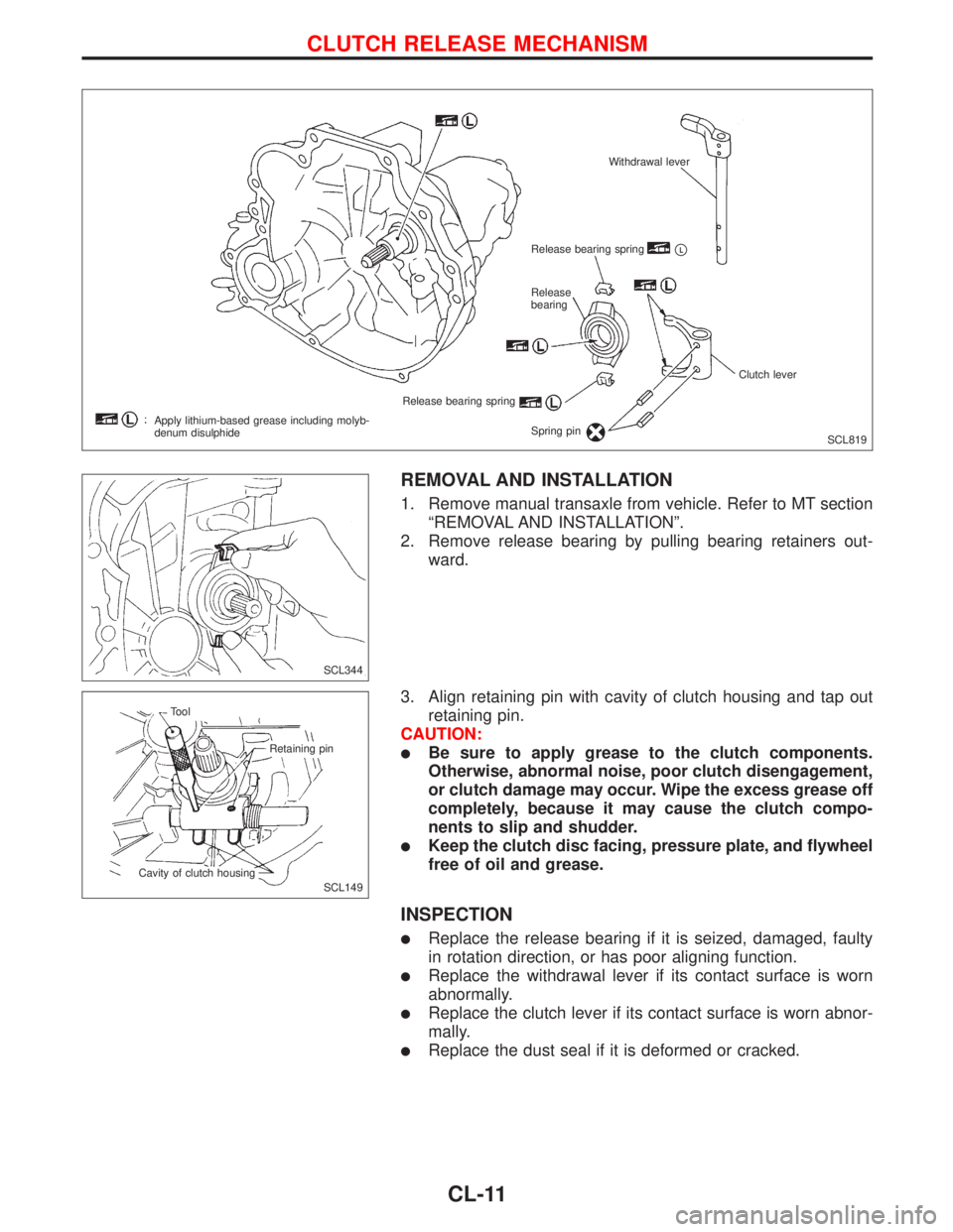
1. Remove manual transaxle from vehicle. Refer to MT section
ªREMOVAL AND INSTALLATIONº.
2. Remove release bearing by pulling bearing retainers out-
ward.
3. Align retaining pin with cavity of clutch housing and tap out
retaining pin.
CAUTION:
lBe sure to apply grease to the clutch components.
Otherwise, abnormal noise, poor clutch disengagement,
or clutch damage may occur. Wipe the excess grease off
completely, because it may cause the clutch compo-
nents to slip and shudder.
lKeep the clutch disc facing, pressure plate, and flywheel
free of oil and grease.
INSPECTION
lReplace the release bearing if it is seized, damaged, faulty
in rotation direction, or has poor aligning function.
lReplace the withdrawal lever if its contact surface is worn
abnormally.
lReplace the clutch lever if its contact surface is worn abnor-
mally.
lReplace the dust seal if it is deformed or cracked.
SCL819 Withdrawal lever
Release bearing spring
pL
Release
bearing
Release bearing spring
Spring pinClutch lever
Apply lithium-based grease including molyb-
denum disulphide
SCL344
SCL149 Tool
Retaining pin
Cavity of clutch housing
CLUTCH RELEASE MECHANISM
CL-11
Page 291 of 2267
Clutch Disc
INSPECTION
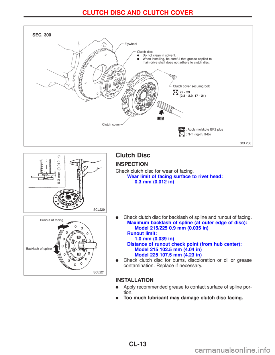
Check clutch disc for wear of facing.
Wear limit of facing surface to rivet head:
0.3 mm (0.012 in)
lCheck clutch disc for backlash of spline and runout of facing.
Maximum backlash of spline (at outer edge of disc):
Model 215/225 0.9 mm (0.035 in)
Runout limit:
1.0 mm (0.039 in)
Distance of runout check point (from hub center):
Model 215 102.5 mm (4.04 in)
Model 225 107.5 mm (4.23 in)
lCheck clutch disc for burns, discoloration or oil or grease
contamination. Replace if necessary.
INSTALLATION
lApply recommended grease to contact surface of spline por-
tion.
lToo much lubricant may damage clutch disc facing.
SCL206 Flywheel
Clutch disc
lDo not clean in solvent.lWhen installing, be careful that grease applied to
main drive shaft does not adhere to clutch disc.
Clutch cover securing bolt
22-29
(2.3 - 2.9, 17 - 21)
: Apply molykote BR2 plus
: N´m (kg-m, ft-lb) Clutch cover
.
.
SEC. 300
SCL229
0.3 mm (0.012 in)
SCL221 Runout of facing
Backlash of spline
CLUTCH DISC AND CLUTCH COVER
CL-13
Page 292 of 2267
Clutch Cover and Flywheel
INSPECTION AND ADJUSTMENT
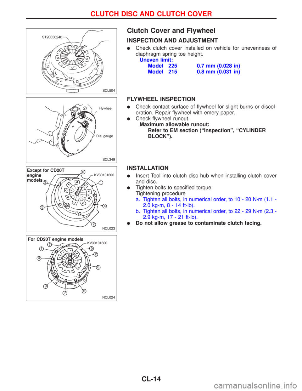
lCheck clutch cover installed on vehicle for unevenness of
diaphragm spring toe height.
Uneven limit:
Model 225 0.7 mm (0.028 in)
Model 215 0.8 mm (0.031 in)
FLYWHEEL INSPECTION
lCheck contact surface of flywheel for slight burns or discol-
oration. Repair flywheel with emery paper.
lCheck flywheel runout.
Maximum allowable runout:
Refer to EM section (ªInspectionº, ªCYLINDER
BLOCKº).
INSTALLATION
lInsert Tool into clutch disc hub when installing clutch cover
and disc.
lTighten bolts to specified torque.
Tightening procedure
a. Tighten all bolts, in numerical order, to 10 - 20 N´m (1.1 -
2.0 kg-m,8-14ft-lb).
b. Tighten all bolts, in numerical order, to 22 - 29 N´m (2.3 -
2.9 kg-m, 17 - 21 ft-lb).
lDo not allow grease to contaminate clutch facing.
SCL504
SCL349 Flywheel
Dial gauge
NCL023
Except for CD20T
engine
models6
1 KV30101600
4
2 53
NCL024 KV30101600
For CD20T engine models
1
2
3 45
6 7
8
9
CLUTCH DISC AND CLUTCH COVER
CL-14
Page 300 of 2267
Supplemental Restraint System (SRS) ªAIR
BAGº and ªSEAT BELT PRE-TENSIONERº
NCEC0002
The Supplemental Restraint System ªAIR BAGº and ªSEAT BELT PRE-TENSIONERº, used along with a seat
belt, help to reduce the risk or severity of injury to the driver and front passenger in a frontal collision. The
Supplemental Restraint System consists of air bag modules (located in the center of the steering wheel and
on the instrument panel on the passenger side), seat belt pre-tensioners, a diagnosis sensor unit, warning
lamp, wiring harness and spiral cable.
In addition to the supplemental air bag modules for a frontal collision, the supplemental side air bag used
along with the seat belt helps to reduce the risk or severity of injury to the driver and front passenger in a
side collision. The supplemental side air bag consists of air bag modules (located in the outer side of front
seats), satellite sensor, diagnosis sensor unit (one of components of supplemental air bags for a frontal
collision), wiring harness, warning lamp (one of components of supplemental air bags for a frontal collision).
Information necessary to service the system safely is included in theRS sectionof this Service Manual.
WARNING:
lTo avoid rendering the SRS inoperative, which could increase the risk of personal injury or death
in the event of a collision which would result in air bag inflation, all maintenance must be per-
formed by an authorized NISSAN dealer.
lImproper maintenance, including incorrect removal and installation of the SRS, can lead to per-
sonal injury caused by unintentional activation of the system.
lDo not use electrical test equipment on any circuit related to the SRS unless instructed to in this
Service Manual. SRS wiring harnesses (except ªSEAT BELT PRE-TENSIONERº connector) can be
identified with yellow harness connector (and with yellow harness protector or yellow insulation
tape before the harness connectors).
Precautions for On Board Diagnostic (OBD)
System of Engine
NCEC0003
The ECM has an on board diagnostic system. It will light up the malfunction indicator (MI) to warn the driver
of a malfunction causing emission deterioration.
CAUTION:
lBe sure to turn the ignition switch ªOFFº and disconnect the negative battery terminal before any
repair or inspection work. The open/short circuit of related switches, sensors, solenoid valves,
etc. will cause the MI to light up.
lBe sure to connect and lock the connectors securely after work. A loose (unlocked) connector
will cause the MI to light up due to the open circuit. (Be sure the connector is free from water,
grease, dirt, bent terminals, etc.)
lCertain systems and components, especially those related to OBD, may use a new style slide-
locking type harness connector.
For description and how to disconnect, refer to EL section, ªDescriptionº, ªHARNESS CONNEC-
TORº.
lBe sure to route and secure the harnesses properly after work. The interference of the harness
with a bracket, etc. may cause the MI to light up due to the short circuit.
lBe sure to connect rubber tubes properly after work. A misconnected or disconnected rubber
tube may cause the MI to light up due to the malfunction of the EGR system or fuel injection
system, etc.
lBe sure to erase the unnecessary malfunction information (repairs completed) from the ECM
before returning the vehicle to the customer.
PRECAUTIONS AND PREPARATIONCD20T
EC-6
Page 331 of 2267
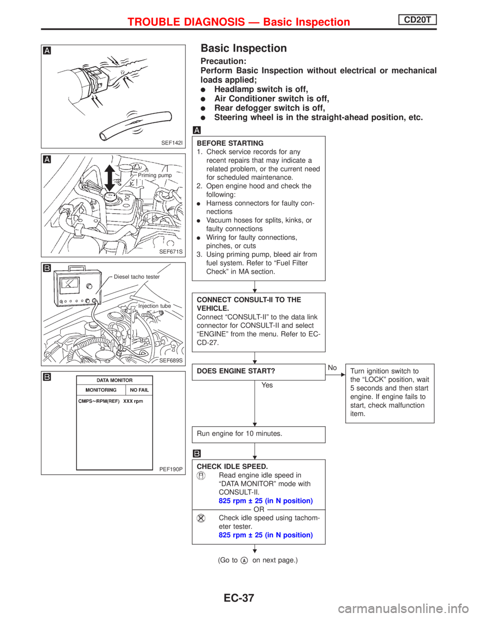
Basic Inspection
Precaution:
Perform Basic Inspection without electrical or mechanical
loads applied;
lHeadlamp switch is off,
lAir Conditioner switch is off,
lRear defogger switch is off,
lSteering wheel is in the straight-ahead position, etc.
BEFORE STARTING
1. Check service records for any
recent repairs that may indicate a
related problem, or the current need
for scheduled maintenance.
2. Open engine hood and check the
following:
lHarness connectors for faulty con-
nections
lVacuum hoses for splits, kinks, or
faulty connections
lWiring for faulty connections,
pinches, or cuts
3. Using priming pump, bleed air from
fuel system. Refer to ªFuel Filter
Checkº in MA section.
CONNECT CONSULT-II TO THE
VEHICLE.
Connect ªCONSULT-IIº to the data link
connector for CONSULT-II and select
ªENGINEº from the menu. Refer to EC-
CD-27.
DOES ENGINE START?
Ye s
ENo
Turn ignition switch to
the ªLOCKº position, wait
5 seconds and then start
engine. If engine fails to
start, check malfunction
item.
Run engine for 10 minutes.
CHECK IDLE SPEED.
Read engine idle speed in
ªDATA MONITORº mode with
CONSULT-II.
825 rpm 25 (in N position)
---------------------------------------------------------------------------------------------------------------------------------OR---------------------------------------------------------------------------------------------------------------------------------
Check idle speed using tachom-
eter tester.
825 rpm 25 (in N position)
(Go topAon next page.)
SEF142I
SEF671S
Priming pump
SEF689S
.Diesel tacho tester
.Injection tube
PEF190P
H
H
H
H
H
TROUBLE DIAGNOSIS Ð Basic InspectionCD20T
EC-37
Page 333 of 2267
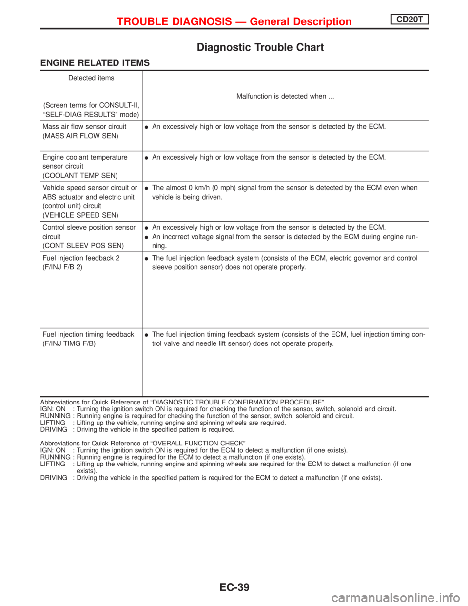
Diagnostic Trouble Chart
ENGINE RELATED ITEMS
Detected items
(Screen terms for CONSULT-II,
ªSELF-DIAG RESULTSº mode)Malfunction is detected when ...
Mass air flow sensor circuit
(MASS AIR FLOW SEN)
lAn excessively high or low voltage from the sensor is detected by the ECM.
Engine coolant temperature
sensor circuit
(COOLANT TEMP SEN)
lAn excessively high or low voltage from the sensor is detected by the ECM.
Vehicle speed sensor circuit or
ABS actuator and electric unit
(control unit) circuit
(VEHICLE SPEED SEN)
lThe almost 0 km/h (0 mph) signal from the sensor is detected by the ECM even when
vehicle is being driven.
Control sleeve position sensor
circuit
(CONT SLEEV POS SEN)
lAn excessively high or low voltage from the sensor is detected by the ECM.
lAn incorrect voltage signal from the sensor is detected by the ECM during engine run-
ning.
Fuel injection feedback 2
(F/INJ F/B 2)
lThe fuel injection feedback system (consists of the ECM, electric governor and control
sleeve position sensor) does not operate properly.
Fuel injection timing feedback
(F/INJ TIMG F/B)
lThe fuel injection timing feedback system (consists of the ECM, fuel injection timing con-
trol valve and needle lift sensor) does not operate properly.
Abbreviations for Quick Reference of ªDIAGNOSTIC TROUBLE CONFIRMATION PROCEDUREº
IGN: ON : Turning the ignition switch ON is required for checking the function of the sensor, switch, solenoid and circuit.
RUNNING : Running engine is required for checking the function of the sensor, switch, solenoid and circuit.
LIFTING : Lifting up the vehicle, running engine and spinning wheels are required.
DRIVING : Driving the vehicle in the specified pattern is required.
Abbreviations for Quick Reference of ªOVERALL FUNCTION CHECKº
IGN: ON : Turning the ignition switch ON is required for the ECM to detect a malfunction (if one exists).
RUNNING : Running engine is required for the ECM to detect a malfunction (if one exists).
LIFTING : Lifting up the vehicle, running engine and spinning wheels are required for the ECM to detect a malfunction (if one
exists).
DRIVING : Driving the vehicle in the specified pattern is required for the ECM to detect a malfunction (if one exists).
TROUBLE DIAGNOSIS Ð General DescriptionCD20T
EC-39
Page 335 of 2267
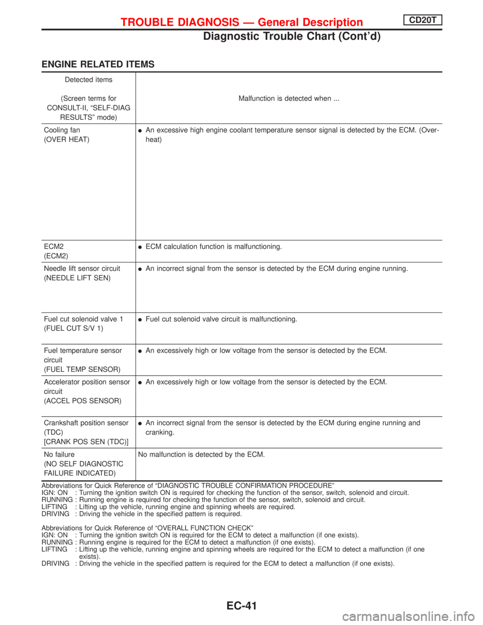
ENGINE RELATED ITEMS
Detected items
(Screen terms for
CONSULT-II, ªSELF-DIAG
RESULTSº mode)Malfunction is detected when ...
Cooling fan
(OVER HEAT)
lAn excessive high engine coolant temperature sensor signal is detected by the ECM. (Over-
heat)
ECM2
(ECM2)
lECM calculation function is malfunctioning.
Needle lift sensor circuit
(NEEDLE LIFT SEN)
lAn incorrect signal from the sensor is detected by the ECM during engine running.
Fuel cut solenoid valve 1
(FUEL CUT S/V 1)
lFuel cut solenoid valve circuit is malfunctioning.
Fuel temperature sensor
circuit
(FUEL TEMP SENSOR)
lAn excessively high or low voltage from the sensor is detected by the ECM.
Accelerator position sensor
circuit
(ACCEL POS SENSOR)
lAn excessively high or low voltage from the sensor is detected by the ECM.
Crankshaft position sensor
(TDC)
[CRANK POS SEN (TDC)]
lAn incorrect signal from the sensor is detected by the ECM during engine running and
cranking.
No failure
(NO SELF DIAGNOSTIC
FAILURE INDICATED)No malfunction is detected by the ECM.
Abbreviations for Quick Reference of ªDIAGNOSTIC TROUBLE CONFIRMATION PROCEDUREº
IGN: ON : Turning the ignition switch ON is required for checking the function of the sensor, switch, solenoid and circuit.
RUNNING : Running engine is required for checking the function of the sensor, switch, solenoid and circuit.
LIFTING : Lifting up the vehicle, running engine and spinning wheels are required.
DRIVING : Driving the vehicle in the specified pattern is required.
Abbreviations for Quick Reference of ªOVERALL FUNCTION CHECKº
IGN: ON : Turning the ignition switch ON is required for the ECM to detect a malfunction (if one exists).
RUNNING : Running engine is required for the ECM to detect a malfunction (if one exists).
LIFTING : Lifting up the vehicle, running engine and spinning wheels are required for the ECM to detect a malfunction (if one
exists).
DRIVING : Driving the vehicle in the specified pattern is required for the ECM to detect a malfunction (if one exists).
TROUBLE DIAGNOSIS Ð General DescriptionCD20T
Diagnostic Trouble Chart (Cont'd)
EC-41