Page 207 of 2267
Diagnostic Procedure 6 (ABS works
frequently)
CHECK WHEEL SENSOR.
1. Check wheel sensor connector for termi-
nal damage or loose connections.
2. Perform wheel sensor mechanical check.
Refer to Diagnostic Procedure 1, BR-77.
OK
ENG
Perform Preliminary check.
Refer to BR-59.
CHECK FRONT AXLES
Check front axles for excessive looseness.
Refer to FA and RA section (ªFront/Rear
Wheel Bearingº, ªON-VEHICLE SERVICEº).
OK
ENG
Repair.
Go toin Diagnostic Procedure 8,
BR-86.
H
H
TROUBLE DIAGNOSES FOR SYMPTOMS
BR-85
Page 208 of 2267
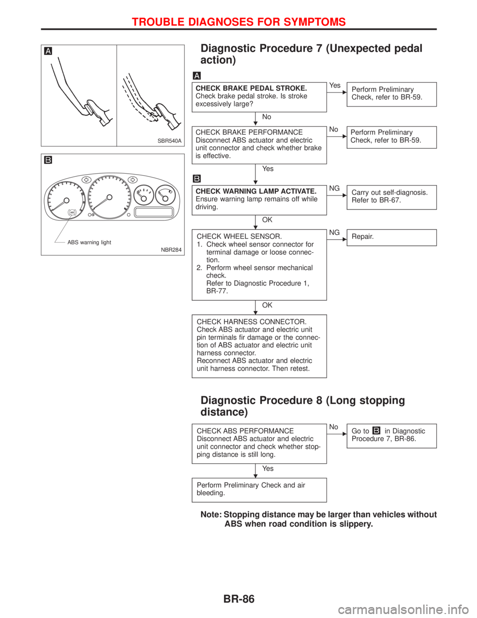
Diagnostic Procedure 7 (Unexpected pedal
action)
CHECK BRAKE PEDAL STROKE.
Check brake pedal stroke. Is stroke
excessively large?
No
EYe s
Perform Preliminary
Check, refer to BR-59.
CHECK BRAKE PERFORMANCE
Disconnect ABS actuator and electric
unit connector and check whether brake
is effective.
Ye s
ENo
Perform Preliminary
Check, refer to BR-59.
CHECK WARNING LAMP ACTIVATE.
Ensure warning lamp remains off while
driving.
OK
ENG
Carry out self-diagnosis.
Refer to BR-67.
CHECK WHEEL SENSOR.
1. Check wheel sensor connector for
terminal damage or loose connec-
tion.
2. Perform wheel sensor mechanical
check.
Refer to Diagnostic Procedure 1,
BR-77.
OK
ENG
Repair.
CHECK HARNESS CONNECTOR.
Check ABS actuator and electric unit
pin terminals fir damage or the connec-
tion of ABS actuator and electric unit
harness connector.
Reconnect ABS actuator and electric
unit harness connector. Then retest.
Diagnostic Procedure 8 (Long stopping
distance)
CHECK ABS PERFORMANCE
Disconnect ABS actuator and electric
unit connector and check whether stop-
ping distance is still long.
Ye s
ENo
Go toin Diagnostic
Procedure 7, BR-86.
Perform Preliminary Check and air
bleeding.
Note: Stopping distance may be larger than vehicles without
ABS when road condition is slippery.
SBR540A
NBR284 ABS warning light
H
H
H
H
H
TROUBLE DIAGNOSES FOR SYMPTOMS
BR-86
Page 209 of 2267
Diagnostic Procedure 9 (ABS does not
work.)
CHECK WARNING LAMP ACTIVATE.
Does the ABS warning lamp activate?
No
EYe s
Carry out self-diagnosis.
Refer to BR-67.
Go toin Diagnostic Procedure 7,
BR-86.
Note: ABS does not work when vehicle speed is under 10
km/h (6 MPH).
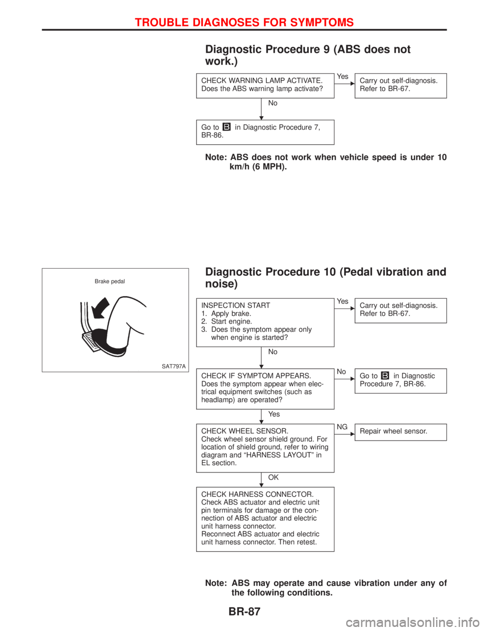
Diagnostic Procedure 10 (Pedal vibration and
noise)
INSPECTION START
1. Apply brake.
2. Start engine.
3. Does the symptom appear only
when engine is started?
No
EYe s
Carry out self-diagnosis.
Refer to BR-67.
CHECK IF SYMPTOM APPEARS.
Does the symptom appear when elec-
trical equipment switches (such as
headlamp) are operated?
Ye s
ENo
Go toin Diagnostic
Procedure 7, BR-86.
CHECK WHEEL SENSOR.
Check wheel sensor shield ground. For
location of shield ground, refer to wiring
diagram and ªHARNESS LAYOUTº in
EL section.
OK
ENG
Repair wheel sensor.
CHECK HARNESS CONNECTOR.
Check ABS actuator and electric unit
pin terminals for damage or the con-
nection of ABS actuator and electric
unit harness connector.
Reconnect ABS actuator and electric
unit harness connector. Then retest.
Note: ABS may operate and cause vibration under any of
the following conditions.
SAT797A Brake pedal
H
H
H
H
TROUBLE DIAGNOSES FOR SYMPTOMS
BR-87
Page 216 of 2267
Service Notice
lWhen removing or installing various parts, place a cloth or padding onto the vehicle body to prevent
scratches.
lHandle trim, molding, instruments, grille, etc. carefully during removing or installing. Be careful not to soil
or damage them.
lApply sealing compound where necessary when installing parts.
lWhen applying sealing compound, be careful that the sealing compound does not protrude from parts.
lWhen replacing any metal parts (for example body outer panel, members, etc.), be sure to take rust
prevention measures.
Supplemental Restraint System (SRS) ªAIR
BAGº and ªSEAT BELT PRE-TENSIONERº
The Supplemental Restraint System ªAir Bagº and ªSeat Belt Pre-tensionerº, used along with a seat belt,
helps to reduce the risk or severity of injury to the driver and front passenger in a frontal collision. The
Supplemental Restraint System consists of air bag modules (located in the center of the steering wheel and
on the instrument panel on the passenger side), seat belt pre-tensioners, a diagnosis sensor unit, warning
lamp, wiring harness and spiral cable. Information necessary to service the system safely is included in the
RS sectionof the Service Manual.
If the vehicle is equipped with side air bag as the Supplemental Restraint System, the side air bag used along
with the seat belt helps to reduce the risk or severity of injury to the driver and front passenger in a side
collision. The side air bag consists of air bag modules (located in the outer side of front seats), satellite
sensor, diagnosis sensor unit (which is one of components of air bags for a frontal collision), wiring harness,
warning lamp (which is one of components of air bags for a frontal collision).
WARNING:
lTo avoid rendering the SRS inoperative (which could increase the risk of personal injury or death
in the event of a collision which would result in air bag inflation) all maintenance must be per-
formed by an authorized NISSAN dealer.
lImproper maintenance, including incorrect removal and installation of the SRS, can lead to per-
sonal injury caused by unintentional activation of the system.
lDo not use electrical test equipment on any circuit related to the SRS unless instructed to do so
in this Service Manual. SRS wiring harnesses are covered with yellow insulation (either just
before the harness connectors or for the complete harness) for easy identification.
PRECAUTIONS
BT-2
Page 229 of 2267
CAUTION:
lDisconnect both battery cables in advance.
lDisconnect air bag system line in advance.
lNever tamper with or force air bag lid open, as this may adversely affect air bag performance.
lBe careful not to scratch pad and other parts.
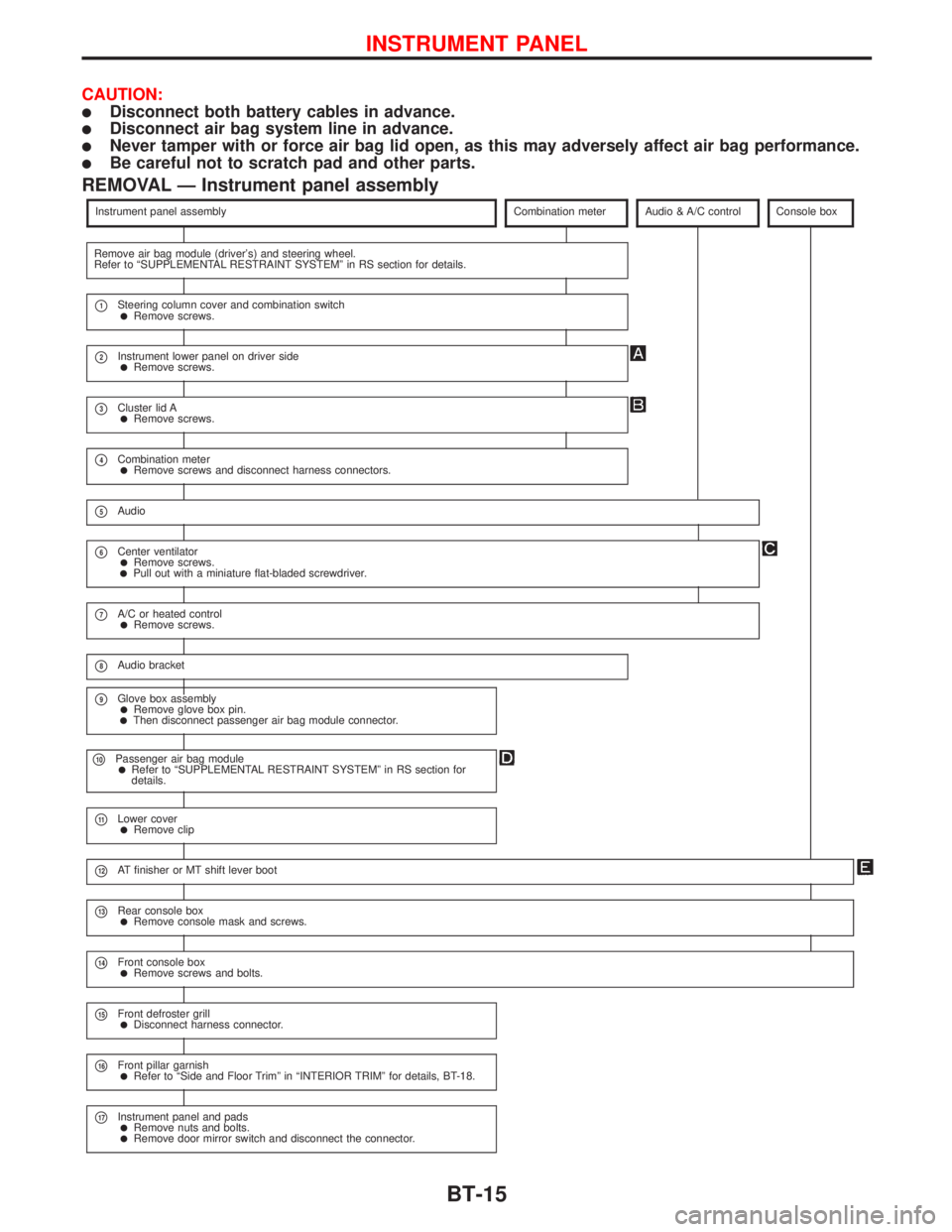
REMOVAL Ð Instrument panel assembly
Instrument panel assemblyCombination meterAudio & A/C controlConsole box
Remove air bag module (driver's) and steering wheel.
Refer to ªSUPPLEMENTAL RESTRAINT SYSTEMº in RS section for details.
p1Steering column cover and combination switchlRemove screws.
p2Instrument lower panel on driver sidelRemove screws.
p3Cluster lid AlRemove screws.
p4Combination meterlRemove screws and disconnect harness connectors.
p5Audio
p6Center ventilatorlRemove screws.lPull out with a miniature flat-bladed screwdriver.
p7A/C or heated controllRemove screws.
p8Audio bracket
p9Glove box assemblylRemove glove box pin.lThen disconnect passenger air bag module connector.
p10Passenger air bag modulelRefer to ªSUPPLEMENTAL RESTRAINT SYSTEMº in RS section for
details.
p11Lower coverlRemove clip
p12AT finisher or MT shift lever boot
p13Rear console boxlRemove console mask and screws.
p14Front console boxlRemove screws and bolts.
p15Front defroster grilllDisconnect harness connector.
p16Front pillar garnishlRefer to ªSide and Floor Trimº in ªINTERIOR TRIMº for details, BT-18.
p17Instrument panel and padslRemove nuts and bolts.lRemove door mirror switch and disconnect the connector.
INSTRUMENT PANEL
BT-15
Page 265 of 2267
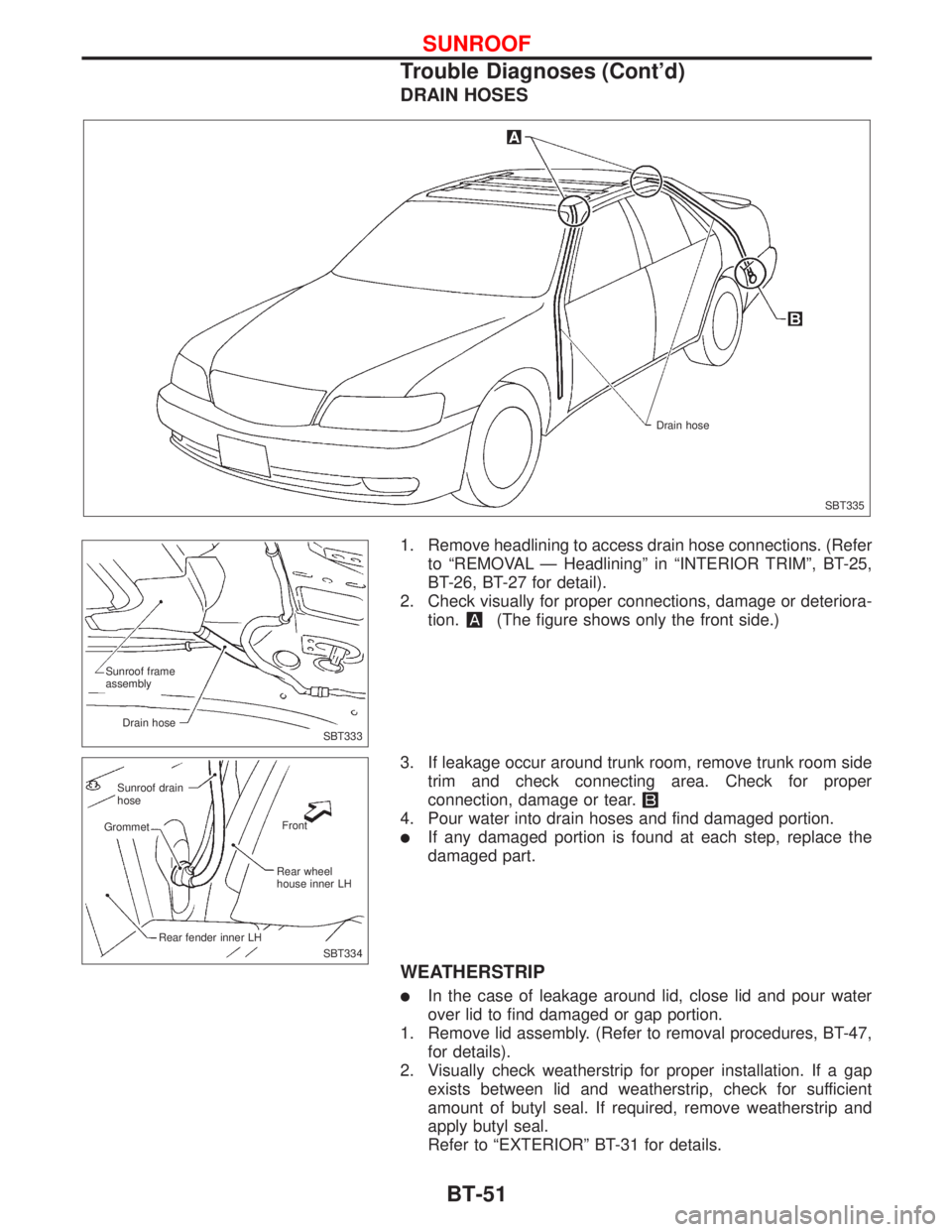
DRAIN HOSES
1. Remove headlining to access drain hose connections. (Refer
to ªREMOVAL Ð Headliningº in ªINTERIOR TRIMº, BT-25,
BT-26, BT-27 for detail).
2. Check visually for proper connections, damage or deteriora-
tion.
(The figure shows only the front side.)
3. If leakage occur around trunk room, remove trunk room side
trim and check connecting area. Check for proper
connection, damage or tear.
4. Pour water into drain hoses and find damaged portion.
lIf any damaged portion is found at each step, replace the
damaged part.
WEATHERSTRIP
lIn the case of leakage around lid, close lid and pour water
over lid to find damaged or gap portion.
1. Remove lid assembly. (Refer to removal procedures, BT-47,
for details).
2. Visually check weatherstrip for proper installation. If a gap
exists between lid and weatherstrip, check for sufficient
amount of butyl seal. If required, remove weatherstrip and
apply butyl seal.
Refer to ªEXTERIORº BT-31 for details.
SBT335 Drain hose
SBT333 Sunroof frame
assembly
Drain hose
SBT334
.Sunroof drain
hose
Front
Grommet
Rear wheel
house inner LH
Rear fender inner LH
SUNROOF
Trouble Diagnoses (Cont'd)
BT-51
Page 279 of 2267
CLUTCH
SECTION
CL
CONTENTS
PRECAUTIONS AND PREPARATION.......................... 2
Precautions ................................................................ 2
Preparation ................................................................ 2
NOISE, VIBRATION AND HARSHNESS (NVH)
TROUBLESHOOTING................................................... 3
NVH Troubleshooting Chart....................................... 3
CLUTCH SYSTEM......................................................... 4
INSPECTION AND ADJUSTMENT............................... 5
Inspecting and Adjusting Clutch Pedal ...................... 5
Bleeding Procedure ................................................... 7HYDRAULIC CLUTCH CONTROL............................... 8
Clutch Master Cylinder .............................................. 8
Clutch Operating Cylinder ......................................... 9
Clutch Damper ......................................................... 10
CLUTCH RELEASE MECHANISM.............................. 11
CLUTCH DISC AND CLUTCH COVER...................... 13
Clutch Disc............................................................... 13
Clutch Cover and Flywheel ..................................... 14
SERVICE DATA AND SPECIFICATIONS (SDS)........ 15
General Specifications ............................................. 15
Inspection and Adjustment ...................................... 16
CL
Page 281 of 2267
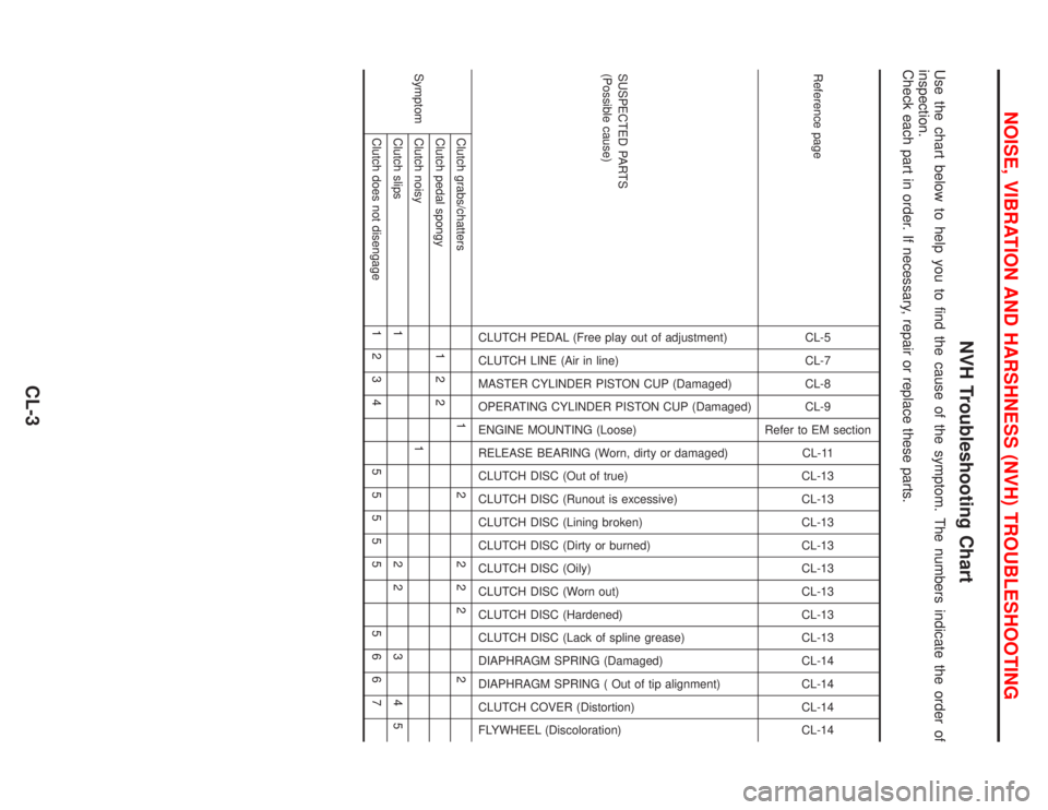
NVH Troubleshooting Chart
Use the chart below to help you to find the cause of the symptom. The numbers indicate the order of
inspection.
Check each part in order. If necessary, repair or replace these parts.
Reference pageCL-5
CL-7
CL-8
CL-9
Refer to EM section
CL-11
CL-13
CL-13
CL-13
CL-13
CL-13
CL-13
CL-13
CL-13
CL-14
CL-14
CL-14
CL-14
SUSPECTED PARTS
(Possible cause)
CLUTCH PEDAL (Free play out of adjustment)
CLUTCH LINE (Air in line)
MASTER CYLINDER PISTON CUP (Damaged)
OPERATING CYLINDER PISTON CUP (Damaged)
ENGINE MOUNTING (Loose)
RELEASE BEARING (Worn, dirty or damaged)
CLUTCH DISC (Out of true)
CLUTCH DISC (Runout is excessive)
CLUTCH DISC (Lining broken)
CLUTCH DISC (Dirty or burned)
CLUTCH DISC (Oily)
CLUTCH DISC (Worn out)
CLUTCH DISC (Hardened)
CLUTCH DISC (Lack of spline grease)
DIAPHRAGM SPRING (Damaged)
DIAPHRAGM SPRING ( Out of tip alignment)
CLUTCH COVER (Distortion)
FLYWHEEL (Discoloration)
SymptomClutch grabs/chatters 1 2 2 2 2 2
Clutch pedal spongy 1 2 2
Clutch noisy 1
Clutch slips 1 2 2 3 4 5
Clutch does not disengage 1 2 3 4 5 5 5 5 5 5 6 6 7
NOISE, VIBRATION AND HARSHNESS (NVH) TROUBLESHOOTING
CL-3