Page 1804 of 2267
lALPHABETICAL INDEXis provided at the end of this manual so that you can rapidly find the item and
page you are searching for.
lA QUICK REFERENCE INDEX,a black tab (e.g.) is provided on the first page. You can quickly
find the first page of each section by mating it to the section's black tab.
lTHE CONTENTSare listed on the first page of each section.
lTHE TITLEis indicated on the upper portion of each page and shows the part or system.
lTHE PAGE NUMBERof each section consists of two letters which designate the particular section and
a number (e.g. ªBR-5º).
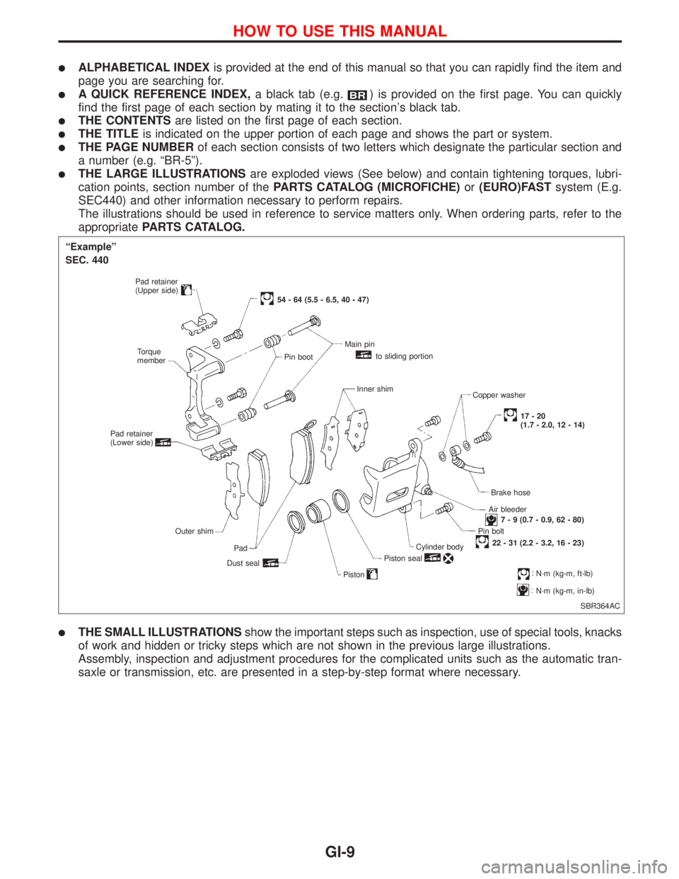
lTHE LARGE ILLUSTRATIONSare exploded views (See below) and contain tightening torques, lubri-
cation points, section number of thePARTS CATALOG (MICROFICHE)or(EURO)FASTsystem (E.g.
SEC440) and other information necessary to perform repairs.
The illustrations should be used in reference to service matters only. When ordering parts, refer to the
appropriatePARTS CATALOG.
lTHE SMALL ILLUSTRATIONSshow the important steps such as inspection, use of special tools, knacks
of work and hidden or tricky steps which are not shown in the previous large illustrations.
Assembly, inspection and adjustment procedures for the complicated units such as the automatic tran-
saxle or transmission, etc. are presented in a step-by-step format where necessary.
SBR364AC
ªExampleº
SEC. 440
Pad retainer
(Upper side)
Torque
member
Pad retainer
(Lower side)
Outer shim
Pad
Dust seal
54 - 64 (5.5 - 6.5, 40 - 47)
Pin bootMain pin
to sliding portion
Inner shim
Copper washer
17-20
(1.7 - 2.0, 12 - 14)
Brake hose
Air bleeder
7 - 9 (0.7 - 0.9, 62 - 80)
Pin bolt
22 - 31 (2.2 - 3.2, 16 - 23)
Cylinder body
Piston seal
PistonN´m (kg-m, ft-lb)
N´m (kg-m, in-lb)
HOW TO USE THIS MANUAL
GI-9
Page 2052 of 2267
Changing Engine Oil Filter
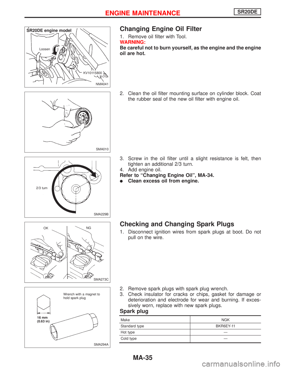
1. Remove oil filter with Tool.
WARNING:
Be careful not to burn yourself, as the engine and the engine
oil are hot.
2. Clean the oil filter mounting surface on cylinder block. Coat
the rubber seal of the new oil filter with engine oil.
3. Screw in the oil filter until a slight resistance is felt, then
tighten an additional 2/3 turn.
4. Add engine oil.
Refer to“Changing Engine Oil”, MA-34.
�Clean excess oil from engine.
Checking and Changing Spark Plugs
1. Disconnect ignition wires from spark plugs at boot. Do not
pull on the wire.
2. Remove spark plugs with spark plug wrench.
3. Check insulator for cracks or chips, gasket for damage or
deterioration and electrode for wear and burning. If exces-
sively worn, replace with new spark plugs.
Spark plug
Make NGK
Standard type BKR6EY-11
Hot type—
Cold type—
NMA041 Loosen
.KV10115800
.SR20DE engine model
SMA010
SMA229B 2/3 turn
SMA273C OKNG
SMA294A Wrench with a magnet to
hold spark plug
16 mm
(0.63 in)
ENGINE MAINTENANCESR20DE
MA-35
Page 2070 of 2267
Balancing Wheels
Wheel balance (maximum allowable unbalance):
10 g (0.35 oz) at rim flange.
Tire balance weight:
5 - 60 g (0.18 - 2.12 oz)
Tire Rotation
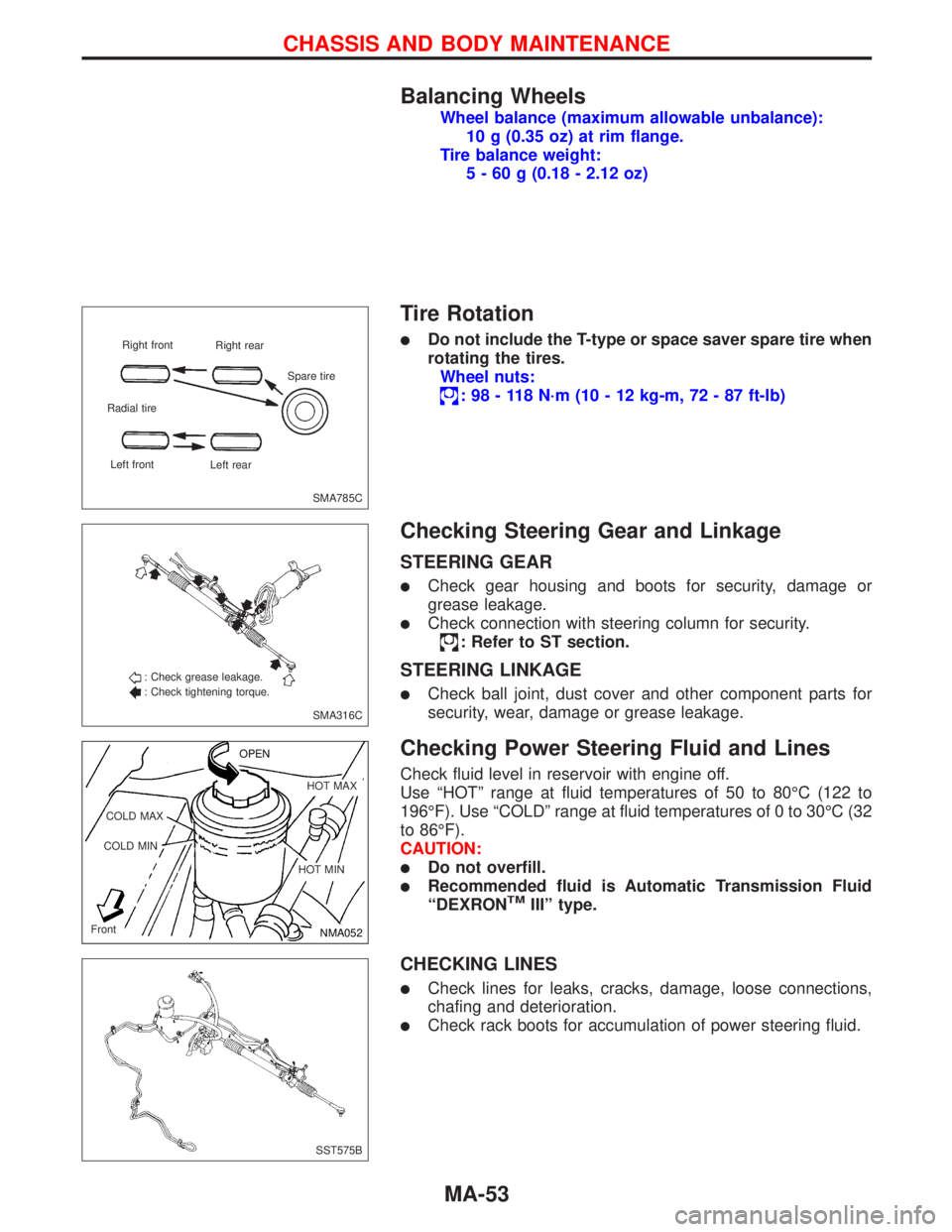
�Do not include the T-type or space saver spare tire when
rotating the tires.
Wheel nuts:
:98-118N·m (10 - 12 kg-m, 72 - 87 ft-lb)
Checking Steering Gear and Linkage
STEERING GEAR
�Check gear housing and boots for security, damage or
grease leakage.
�Check connection with steering column for security.
: Refer to ST section.
STEERING LINKAGE
�Check ball joint, dust cover and other component parts for
security, wear, damage or grease leakage.
Checking Power Steering Fluid and Lines
Check fluid level in reservoir with engine off.
Use“HOT”range at fluid temperatures of 50 to 80°C (122 to
196°F). Use“COLD”range at fluid temperatures of 0 to 30°C (32
to 86°F).
CAUTION:
�Do not overfill.
�Recommended fluid is Automatic Transmission Fluid
“DEXRONTMIII”type.
CHECKING LINES
�Check lines for leaks, cracks, damage, loose connections,
chafing and deterioration.
�Check rack boots for accumulation of power steering fluid.
SMA785C Right front
Right rear
Radial tire
Left front
Left rearSpare tire
SMA316C : Check grease leakage.
: Check tightening torque.
NMA052 OPEN
.HOT MAX
.HOT MIN COLD MAX
COLD MIN
Front
SST575B
CHASSIS AND BODY MAINTENANCE
MA-53
Page 2085 of 2267
Replacing Oil SealNCMT0005
DIFFERENTIAL OIL SEALNCMT0005S01
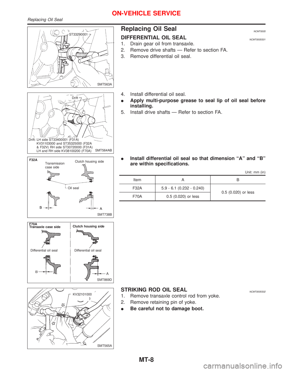
1. Drain gear oil from transaxle.
2. Remove drive shafts Ð Refer to section FA.
3. Remove differential oil seal.
4. Install differential oil seal.
IApply multi-purpose grease to seal lip of oil seal before
installing.
5. Install drive shafts Ð Refer to section FA.
IInstall differential oil seal so that dimension ªAº and ªBº
are within specifications.
Unit: mm (in)
Item A B
F32A 5.9 - 6.1 (0.232 - 0.240)
0.5 (0.020) or less
F70A 0.5 (0.020) or less
STRIKING ROD OIL SEALNCMT0005S02
1. Remove transaxle control rod from yoke.
2. Remove retaining pin of yoke.
IBe careful not to damage boot.
SMT563A ST33290001
SMT564AB Drift
.Drift: LH side ST33400001 (F31A)
KV31103000 and ST35325000 (F32A
& F32V) RH side ST30720000 (F31A)
LH and RH side KV38100200 (F70A)
SMT738B F32A
Transmission
case sideClutch housing side
Oil seal
SMT869D Transaxle case sideClutch housing side
Differential oil seal Differential oil seal F70A
SMT565A KV32101000
ON-VEHICLE SERVICE
Replacing Oil Seal
MT-8
Page 2091 of 2267
Transaxle Gear Control
p1Control lever knob
p2Boot
p3Control lever socket
p4Control lever
p5Bushing
p6Hand lever socket
p7Plate bolt
p8Transaxle hole cover
p9Support rod
p10Plate
p11Collar
p12Bushing
p13Collar
p14Bushing
p15Control rod
p16Return spring
p17Holder bracket
p18Dynamic damper
NMT097
14 - 18 (1.4 - 1.8, 10 - 13)
18 - 24 (1.8 - 2.4, 13 - 17)
22 - 29 (2.2 - 3.0, 16 - 22)
12-15
(1.2-1.5,9-11)
4.4 - 5.9 (0.45 - 0.60, 39.1 - 52.1)
12-15
(1.2-1.5,9-11)
43-55
(4.4 - 5.6,
32 - 41)
SEC. 341
: Apply multi purpose grease
: N´m (kg-m, in-lb)
: N´m (kg-m, ft-lb)
MAJOR OVERHAULRS5F32A
Transaxle Gear Control
MT-14
Page 2124 of 2267
NCMT0008
Transaxle Gear ControlNCMT0008S01
1. Control lever knob
2. Boot
3. Finisher
4. Control lever bracket
5. Dust cover
6. Socket
7. Control lever8. O-ring
9. O-ring
10. Ring spring
11. Bearing seat
12. Seat
13. Return spring
14. Control rod15. Bush
16. Collar
17. Bush
18. Bracket
19. Bush
20. Collar
21. Washer
SMT135D
4.4 - 5.9 (0.45 - 0.60, 39 - 52)
12-15(1.2-1.5,9-11)
18 -24 (1.8 -2.4, 13 - 17)
12-15(1.2-1.5,9-11)
Apply multi-purpose grease.
N´m (kg-m, in-lb)
N´m (kg-m, ft-lb)
14 - 18 (1.4 - 1.8, 10 -13)29 - 37 (3.0 - 3.8, 21 - 27)
22 - 29 (2.2 - 3.0, 16 - 22)
MAJOR OVERHAULRS5F70A
Transaxle Gear Control
MT-47
Page 2125 of 2267
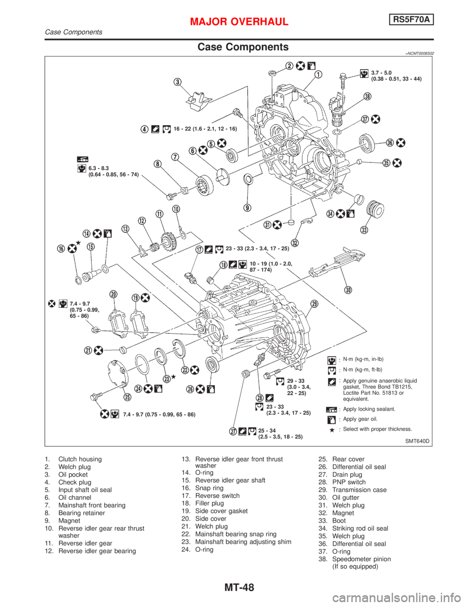
Case Components=NCMT0008S02
1. Clutch housing
2. Welch plug
3. Oil pocket
4. Check plug
5. Input shaft oil seal
6. Oil channel
7. Mainshaft front bearing
8. Bearing retainer
9. Magnet
10. Reverse idler gear rear thrust
washer
11. Reverse idler gear
12. Reverse idler gear bearing13. Reverse idler gear front thrust
washer
14. O-ring
15. Reverse idler gear shaft
16. Snap ring
17. Reverse switch
18. Filler plug
19. Side cover gasket
20. Side cover
21. Welch plug
22. Mainshaft bearing snap ring
23. Mainshaft bearing adjusting shim
24. O-ring25. Rear cover
26. Differential oil seal
27. Drain plug
28. PNP switch
29. Transmission case
30. Oil gutter
31. Welch plug
32. Magnet
33. Boot
34. Striking rod oil seal
35. Welch plug
36. Differential oil seal
37. O-ring
38. Speedometer pinion
(If so equipped)
SMT640D 16 - 22 (1.6 - 2.1, 12 - 16)
6.3 - 8.3
(0.64 - 0.85, 56 - 74)
7.4 - 9.7
(0.75 - 0.99,
65 - 86)
7.4 - 9.7 (0.75 - 0.99, 65 - 86)23 - 33 (2.3 - 3.4, 17 - 25)
10 - 19 (1.0 - 2.0,
87 - 174)3.7 - 5.0
(0.38 - 0.51, 33 - 44)
29-33
(3.0 - 3.4,
22 - 25)
23-33
(2.3 - 3.4, 17 - 25)
25-34
(2.5 - 3.5, 18 - 25)N´m (kg-m, in-lb)
N´m (kg-m, ft-lb)
Apply genuine anaerobic liquid
gasket, Three Bond TB1215,
Loctite Part No. 51813 or
equivalent.
Apply locking sealant.
Apply gear oil.
Select with proper thickness.
MAJOR OVERHAULRS5F70A
Case Components
MT-48
Page 2127 of 2267
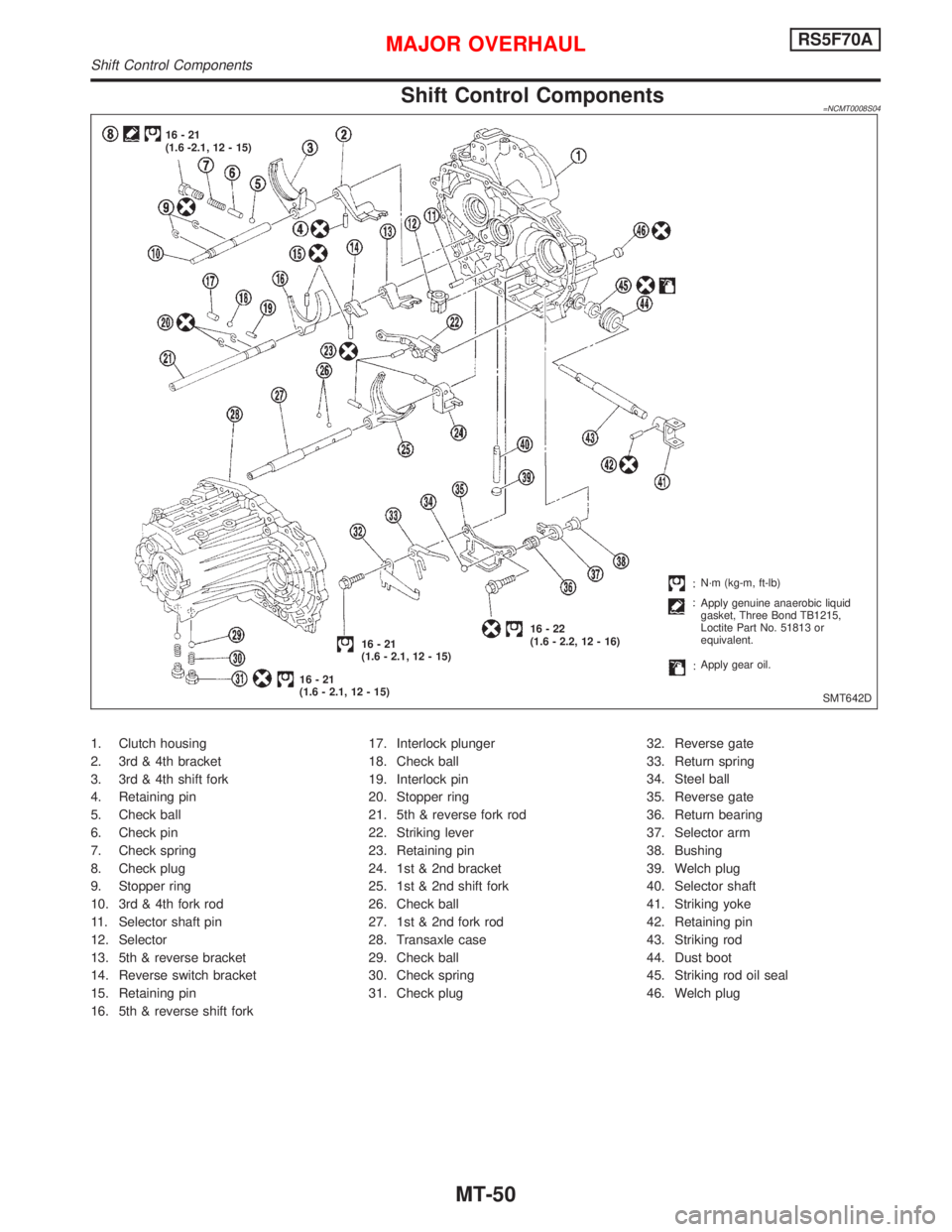
Shift Control Components=NCMT0008S04
1. Clutch housing
2. 3rd & 4th bracket
3. 3rd & 4th shift fork
4. Retaining pin
5. Check ball
6. Check pin
7. Check spring
8. Check plug
9. Stopper ring
10. 3rd & 4th fork rod
11. Selector shaft pin
12. Selector
13. 5th & reverse bracket
14. Reverse switch bracket
15. Retaining pin
16. 5th & reverse shift fork17. Interlock plunger
18. Check ball
19. Interlock pin
20. Stopper ring
21. 5th & reverse fork rod
22. Striking lever
23. Retaining pin
24. 1st & 2nd bracket
25. 1st & 2nd shift fork
26. Check ball
27. 1st & 2nd fork rod
28. Transaxle case
29. Check ball
30. Check spring
31. Check plug32. Reverse gate
33. Return spring
34. Steel ball
35. Reverse gate
36. Return bearing
37. Selector arm
38. Bushing
39. Welch plug
40. Selector shaft
41. Striking yoke
42. Retaining pin
43. Striking rod
44. Dust boot
45. Striking rod oil seal
46. Welch plug
SMT642D 16-21
(1.6 -2.1, 12 - 15)
16-21
(1.6 - 2.1, 12 - 15)16-21
(1.6 - 2.1, 12 - 15)16-22
(1.6 - 2.2, 12 - 16)N´m (kg-m, ft-lb)
Apply genuine anaerobic liquid
gasket, Three Bond TB1215,
Loctite Part No. 51813 or
equivalent.
Apply gear oil.
MAJOR OVERHAULRS5F70A
Shift Control Components
MT-50