Page 2154 of 2267

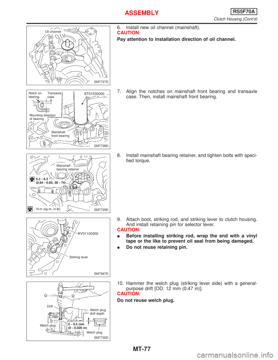
6. Install new oil channel (mainshaft).
CAUTION:
Pay attention to installation direction of oil channel.
7. Align the notches on mainshaft front bearing and transaxle
case. Then, install mainshaft front bearing.
8. Install mainshaft bearing retainer, and tighten bolts with speci-
fied torque.
9. Attach boot, striking rod, and striking lever to clutch housing.
And install retaining pin for selector lever.
CAUTION:
IBefore installing striking rod, wrap the end with a vinyl
tape or the like to prevent oil seal from being damaged.
IDo not reuse retaining pin.
10. Hammer the welch plug (striking lever side) with a general-
purpose drift [OD: 12 mm (0.47 in)].
CAUTION:
Do not reuse welch plug.
SMT727D Oil channel
SMT728D Notch on
bearingTransaxle
case
Mounting direction
of bearing
Mainshaft
front bearing
SMT729D Mainshaft
bearing retainer
6.3 - 8.3
(0.64 - 0.85, 56 - 74)
N´m (kg-m, in-lb)
SMT667D Striking lever
SMT730D Drift
Welch plug0 - 0.5 mm
(0 - 0.020 in)
Welch plugWelch plug
drift depth
ASSEMBLYRS5F70A
Clutch Housing (Cont'd)
MT-77
Page 2249 of 2267

Checking and Adjusting Drive Belts
Refer to section MA for Drive Belt Inspection.
Checking Fluid Level
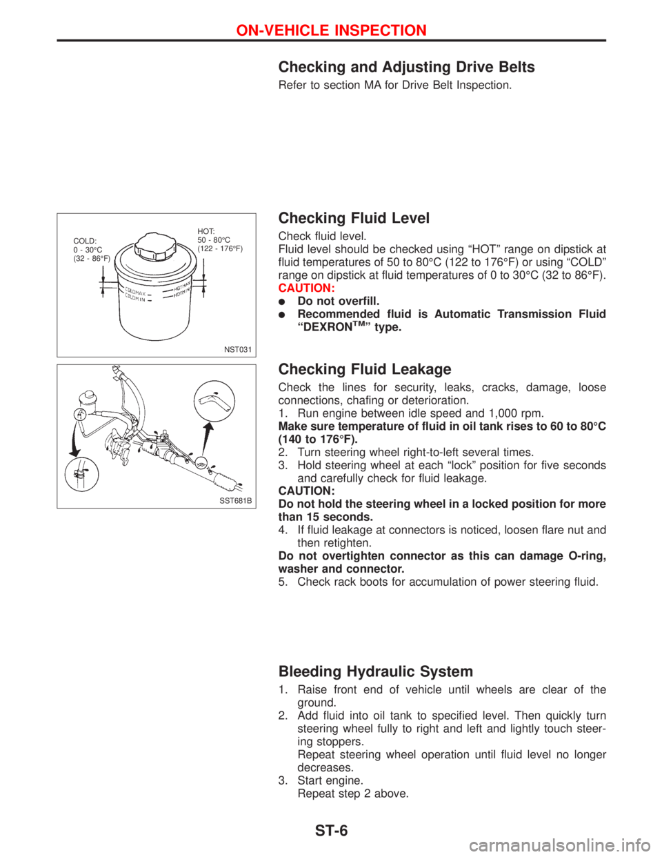
Check fluid level.
Fluid level should be checked using ªHOTº range on dipstick at
fluid temperatures of 50 to 80ÉC (122 to 176ÉF) or using ªCOLDº
range on dipstick at fluid temperatures of 0 to 30ÉC (32 to 86ÉF).
CAUTION:
lDo not overfill.
lRecommended fluid is Automatic Transmission Fluid
ªDEXRONTMº type.
Checking Fluid Leakage
Check the lines for security, leaks, cracks, damage, loose
connections, chafing or deterioration.
1. Run engine between idle speed and 1,000 rpm.
Make sure temperature of fluid in oil tank rises to 60 to 80ÉC
(140 to 176ÉF).
2. Turn steering wheel right-to-left several times.
3. Hold steering wheel at each ªlockº position for five seconds
and carefully check for fluid leakage.
CAUTION:
Do not hold the steering wheel in a locked position for more
than 15 seconds.
4. If fluid leakage at connectors is noticed, loosen flare nut and
then retighten.
Do not overtighten connector as this can damage O-ring,
washer and connector.
5. Check rack boots for accumulation of power steering fluid.
Bleeding Hydraulic System
1. Raise front end of vehicle until wheels are clear of the
ground.
2. Add fluid into oil tank to specified level. Then quickly turn
steering wheel fully to right and left and lightly touch steer-
ing stoppers.
Repeat steering wheel operation until fluid level no longer
decreases.
3. Start engine.
Repeat step 2 above.
NST031 COLD:
0 - 30ÉC
(32 - 86ÉF)HOT:
50 - 80ÉC
(122 - 176ÉF)
SST681B
ON-VEHICLE INSPECTION
ST-6
Page 2254 of 2267
Disassembly and Assembly
WARNING:
Refer to `PRECAUTIONSº (on page ST-2) and to RS section
for spiral cable servicing information.
lTo remove combination switch, remove attaching screws,
disconnect harnesses and remove switch.
NST020 Boot Combination
switch assembly
24-29
(2.4 - 3.0,
17 - 22) Jacket tube assemblyWasherSpiral cable assy
: N´m (kg-m, ft-lb)
: Do not re-use
SEC. 488
O-ring
Snap ring
24-29
(2.4 - 3.0, 17 - 22)
Lower jointColumn shaft assembly
NST021 Screws remain captive in switch
Remove
STEERING WHEEL AND STEERING COLUMN
ST-11
Page 2260 of 2267
Disassembly
Always use soft jaws when clamping steering gear housing
in a vise. Handle gear housing carefully, as it is made of
aluminum.
1. Remove outer tie-rod.
2. Remove dust boot.
Inspection
Thoroughly clean all parts in cleaning solvent or automatic trans-
mission fluid ªDexronTMº type, and blow dry with compressed air,
if available.
SST585B
SEC. 492
NST022
.Jaw
protectors
POWER STEERING GEAR AND LINKAGE
Removal and Installation (Cont'd)
ST-17
Page 2261 of 2267
STEERING GEAR ASSEMBLY
lCheck for smooth operation through a full stroke.
lCheck rack and tie-rod for cracks, deformation or other dam-
age.
lCheck pinion rotating torque.
Pinion rotating torque:
0.8 - 1.3 N´m (8 - 13 kg-cm, 6.9 - 11.3 in-lb)
lCheck rack sliding force.
Rack sliding force:
284 N (29 kg, 64 lb) or less
BOOT
Check condition of boot. If cracked, replace it.
TIE-ROD OUTER AND INNER SOCKET
lCheck ball joint for swinging force.
A Tie-rod outer ball joint:
3.3-67N
(0.34 - 6.8 kg, 0.74 - 15.1 lb)
B Tie-rod inner ball joint:
0.3 - 24.5 N
(0.03 - 2.5 kg, 0.07 - 5.5 lb)
lCheck ball joint for rotating torque.
Tie-rod outer ball joint:
0.15 - 2.9 N´m
(1.5 - 30 kg-cm, 1.3 - 26.0 in-lb)
SST587B
SST090B
SST588B Measuring point
SST751A ST3127S000
POWER STEERING GEAR AND LINKAGE
Inspection (Cont'd)
ST-18
Page 2262 of 2267
lCheck ball joint for axial end play.
Tie-rod outer ball joint:
0mm(0in)
Tie-rod inner ball joint:
0mm(0in)
lCheck condition of dust cover. If cracked excessively, replace
it.
Assembly
1. Measure rack stroke.
Rack stroke ªSº:
Refer to SDS (ST-23)
2. Before installing boot, coat the contact surfaces between
boot and tie-rod with grease.
3. Tighten outer socket lock nut.
Tie-rod length ªLº:
Refer to SDS (ST-24)
SST334B
NST023
SST589B
SST093B
POWER STEERING GEAR AND LINKAGE
Inspection (Cont'd)
ST-19