Page 166 of 2267
Components
1. Boot
2. Piston
3. Piston cap
4. Spring
5. Wheel cylinder6. Shoe hold-down pin
7. Plug
8. Brake drum
9. Shoe hold-down spring
10. Adjuster11. Retainer ring
12. Return spring (Upper)
13. Return spring (Lower)
14. Spring
15. Toggle lever
Removal
WARNING:
Clean brake lining with a vacuum dust collector to minimize
the hazard of airborne materials.
CAUTION:
Make sure parking brake lever is completely released.
SBR616E
REAR DRUM BRAKE
BR-44
Page 167 of 2267
1. Release parking brake lever fully, then remove drum.
If drum is hard to remove, the following procedures
should be carried out.
a. Remove plug. To make shoe clearance, push shoe hold-
down spring to free toggle lever.
b. Install two bolts as shown. Tighten the two bolts gradu-
ally.
2. After removing retainer, remove spring by rotating shoes.
lBe careful not to damage wheel cylinder piston boots.
lBe careful not to damage parking brake cable when
separating it.
3. Remove adjuster.
4. Disconnect parking brake cable from toggle lever.
5. Remove retainer ring with a suitable tool. Then separate
toggle lever and brake shoe.
Inspection Ð Wheel Cylinder
lCheck wheel cylinder for leakage.
lCheck for wear, damage and loose conditions. Replace if any
such condition exists.
SBR617E
SBR020A
SBR214B
SBR329C
SBR330C
REAR DRUM BRAKE
Removal (Cont'd)
BR-45
Page 169 of 2267
3. Shorten adjuster by rotating it.
lTo tighten loosened brake shoes, first, insert a screw driver
in the direction shown in the left. Then, move the adjuster in
the direction shown by the arrow while disengaging the tooth
contact. Never tap the area E.
4. Connect parking brake cable to toggle lever.
5. Install all parts.
Be careful not to damage wheel cylinder piston boots.
6. Check all parts are installed properly.
Pay attention to direction of adjuster assembly.
7. Install brake drum.
8. When installing new wheel cylinder or overhauling wheel
cylinder, bleed air. Refer to ªBleeding Brake Systemº, BR-8.
9. Adjust parking brake. Refer to BR-49.
SBR619E
REAR DRUM BRAKE
Installation (Cont'd)
BR-47
Page 229 of 2267

CAUTION:
lDisconnect both battery cables in advance.
lDisconnect air bag system line in advance.
lNever tamper with or force air bag lid open, as this may adversely affect air bag performance.
lBe careful not to scratch pad and other parts.
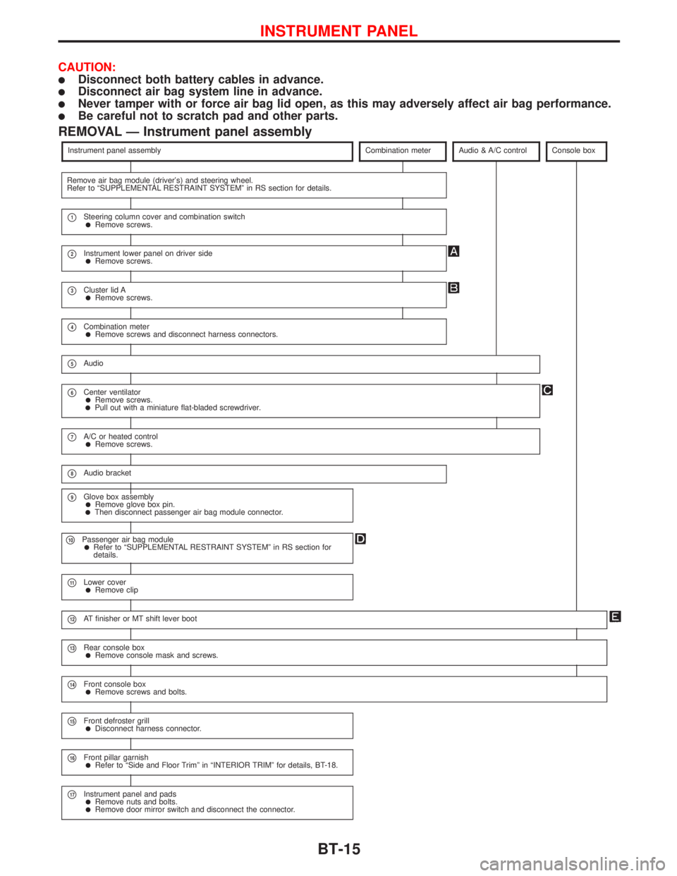
REMOVAL Ð Instrument panel assembly
Instrument panel assemblyCombination meterAudio & A/C controlConsole box
Remove air bag module (driver's) and steering wheel.
Refer to ªSUPPLEMENTAL RESTRAINT SYSTEMº in RS section for details.
p1Steering column cover and combination switchlRemove screws.
p2Instrument lower panel on driver sidelRemove screws.
p3Cluster lid AlRemove screws.
p4Combination meterlRemove screws and disconnect harness connectors.
p5Audio
p6Center ventilatorlRemove screws.lPull out with a miniature flat-bladed screwdriver.
p7A/C or heated controllRemove screws.
p8Audio bracket
p9Glove box assemblylRemove glove box pin.lThen disconnect passenger air bag module connector.
p10Passenger air bag modulelRefer to ªSUPPLEMENTAL RESTRAINT SYSTEMº in RS section for
details.
p11Lower coverlRemove clip
p12AT finisher or MT shift lever boot
p13Rear console boxlRemove console mask and screws.
p14Front console boxlRemove screws and bolts.
p15Front defroster grilllDisconnect harness connector.
p16Front pillar garnishlRefer to ªSide and Floor Trimº in ªINTERIOR TRIMº for details, BT-18.
p17Instrument panel and padslRemove nuts and bolts.lRemove door mirror switch and disconnect the connector.
INSTRUMENT PANEL
BT-15
Page 1323 of 2267
WIPER LINKAGE
* Structure is basically the opposite for RHD models.
Removal
1. Remove 4 bolts that secure wiper motor.
2. Detach wiper motor from wiper linkage at ball joint.
3. Remove wiper linkage.
Be careful not to break ball joint rubber boot.
Installation
�Grease ball joint area before installation.
1. Installation is the reverse order of removal.
MEL664DA
LHD models*
3.8 - 5.1 (0.39 - 0.52, 33.9 - 45.1)
3.8 - 5.1 (0.39 - 0.52, 33.9 - 45.1)
:N·m (kg-m, in-lb)
FRONT WIPER AND WASHER
Removal and Installation (Cont’d)
EL-191
Page 1439 of 2267

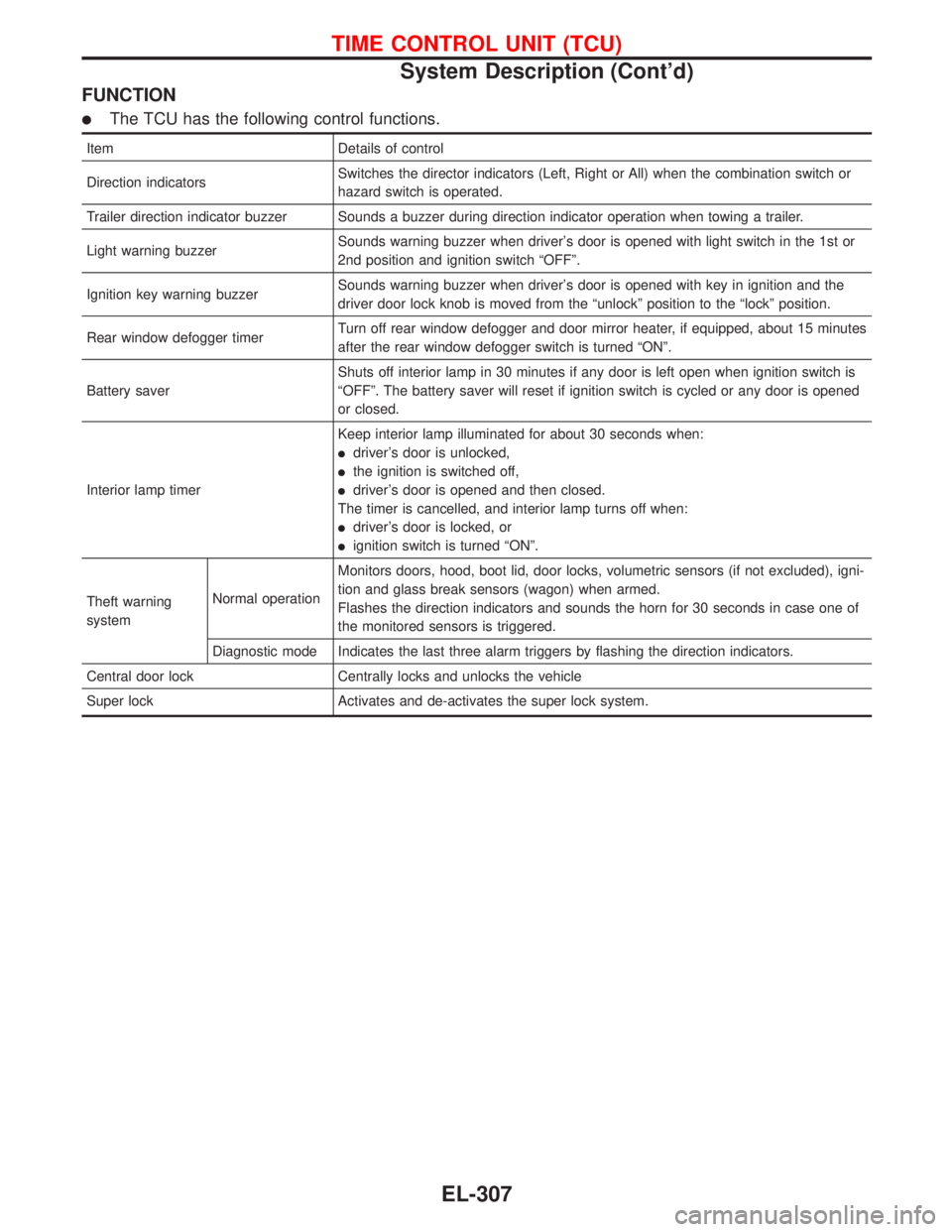
FUNCTION
�The TCU has the following control functions.
Item Details of control
Direction indicatorsSwitches the director indicators (Left, Right or All) when the combination switch or
hazard switch is operated.
Trailer direction indicator buzzer Sounds a buzzer during direction indicator operation when towing a trailer.
Light warning buzzerSounds warning buzzer when driver’s door is opened with light switch in the 1st or
2nd position and ignition switch“OFF”.
Ignition key warning buzzerSounds warning buzzer when driver’s door is opened with key in ignition and the
driver door lock knob is moved from the“unlock”position to the“lock”position.
Rear window defogger timerTurn off rear window defogger and door mirror heater, if equipped, about 15 minutes
after the rear window defogger switch is turned“ON”.
Battery saverShuts off interior lamp in 30 minutes if any door is left open when ignition switch is
“OFF”. The battery saver will reset if ignition switch is cycled or any door is opened
or closed.
Interior lamp timerKeep interior lamp illuminated for about 30 seconds when:
�driver’s door is unlocked,
�the ignition is switched off,
�driver’s door is opened and then closed.
The timer is cancelled, and interior lamp turns off when:
�driver’s door is locked, or
�ignition switch is turned“ON”.
Theft warning
systemNormal operationMonitors doors, hood, boot lid, door locks, volumetric sensors (if not excluded), igni-
tion and glass break sensors (wagon) when armed.
Flashes the direction indicators and sounds the horn for 30 seconds in case one of
the monitored sensors is triggered.
Diagnostic mode Indicates the last three alarm triggers by flashing the direction indicators.
Central door lock Centrally locks and unlocks the vehicle
Super lock Activates and de-activates the super lock system.
TIME CONTROL UNIT (TCU)
System Description (Cont’d)
EL-307
Page 1753 of 2267

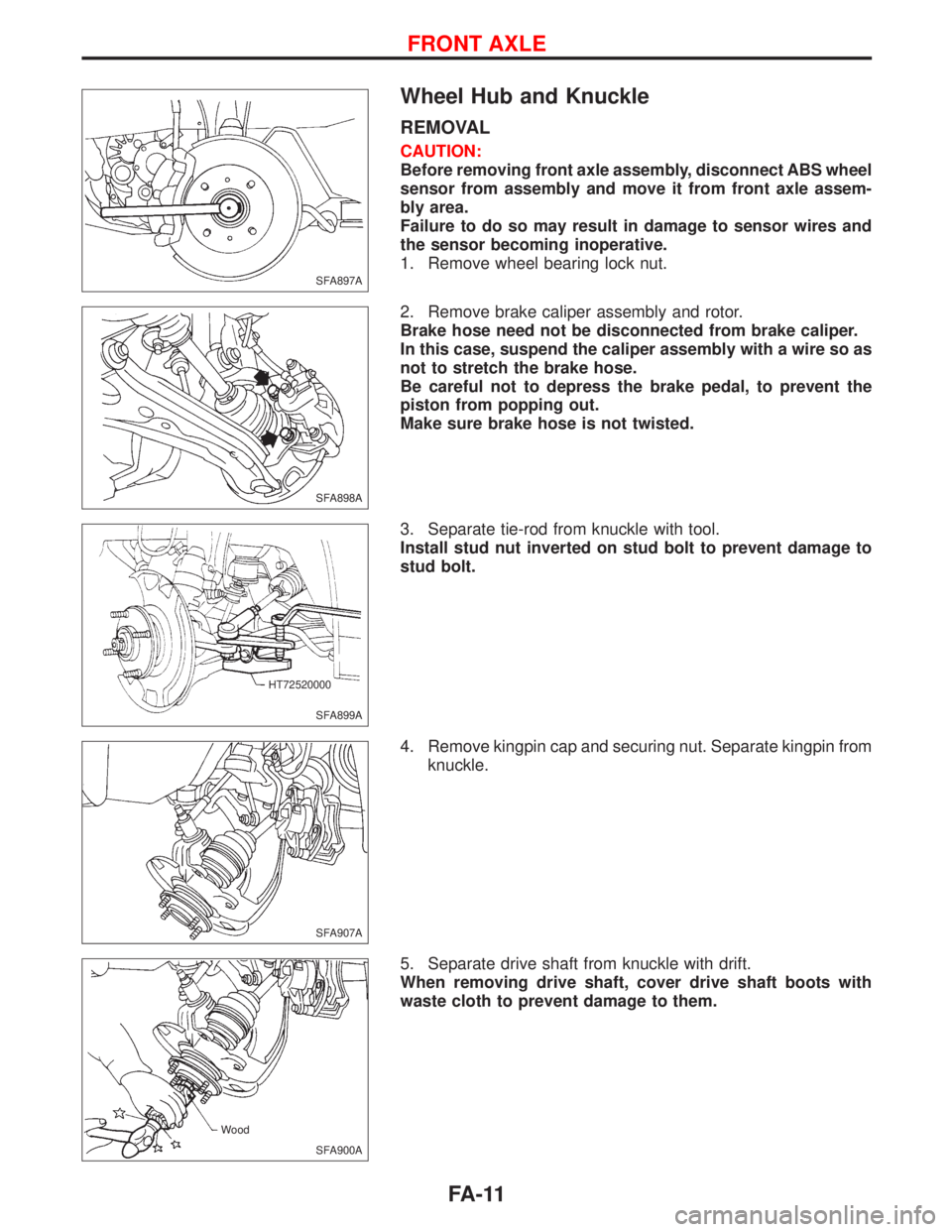
Wheel Hub and Knuckle
REMOVAL
CAUTION:
Before removing front axle assembly, disconnect ABS wheel
sensor from assembly and move it from front axle assem-
bly area.
Failure to do so may result in damage to sensor wires and
the sensor becoming inoperative.
1. Remove wheel bearing lock nut.
2. Remove brake caliper assembly and rotor.
Brake hose need not be disconnected from brake caliper.
In this case, suspend the caliper assembly with a wire so as
not to stretch the brake hose.
Be careful not to depress the brake pedal, to prevent the
piston from popping out.
Make sure brake hose is not twisted.
3. Separate tie-rod from knuckle with tool.
Install stud nut inverted on stud bolt to prevent damage to
stud bolt.
4. Remove kingpin cap and securing nut. Separate kingpin from
knuckle.
5. Separate drive shaft from knuckle with drift.
When removing drive shaft, cover drive shaft boots with
waste cloth to prevent damage to them.
SFA897A
SFA898A
SFA899A HT72520000
SFA907A
SFA900A Wood
FRONT AXLE
FA-11
Page 1757 of 2267
(2) Spin knuckle several turns in both directions.
(3) Make sure that wheel bearings operate smoothly.
Drive shaft
REMOVAL
1. Remove wheel bearing lock nut.
2. Remove brake caliper assembly and rotor.
Brake hose need not be disconnected from brake caliper. In
this case, suspend caliper assembly with wire so as not to
stretch brake hose. Be careful not to depress brake pedal,
or piston will pop out.
Make sure brake hose is not twisted.
3. Remove tie-rod ball joint.
4. Remove upper knuckle nut.
5. Separate drive shaft from knuckle by lightly tapping it. If it is
hard to remove, use a puller.
When removing drive shaft, cover drive shaft boots with
waste cloth to prevent damage to them.
Refer to ªFRONT AXLEº, ªWheel Hub and Knuckleº, FA-11.
6. Remove right drive shaft from transaxle.
þ Models without support bearing þ
þ Models with support bearing þ
SFA182A
SFA897A
SFA907A
.SFA499A
.SFA989
FRONT AXLE
Wheel Hub and Knuckle (Cont'd)
FA-15