1999 DODGE NEON warning
[x] Cancel search: warningPage 378 of 1200
SERVICE PROCEDURES
VEHICLE IMMOBILIZER SYSTEM
WARNING: ON VEHICLES EQUIPPED WITH AIR-
BAGS, REFER TO GROUP 8M - PASSIVE
RESTRAINT SYSTEMS BEFORE ATTEMPTING ANY
STEERING WHEEL, STEERING COLUMN, OR
INSTRUMENT PANEL COMPONENT DIAGNOSIS OR
SERVICE. FAILURE TO TAKE THE PROPER PRE-
CAUTIONS COULD RESULT IN ACCIDENTAL AIR-
BAG DEPLOYMENT AND POSSIBLE PERSONAL
INJURY.
NOTE: The following tests may not prove conclu-
sive in the diagnosis of this system. The most reli-
able, efficient, and accurate means to diagnose the
Vehicle Immobilizer System involves the use of a
DRB scan tool. Refer to the Vehicle Theft Security
System menu item on the DRB scan tool for the
procedures.
The vehicle immobilizer system and the Chrysler
Collision Detection (CCD) data bus network should
be diagnosed using the DRB scan tool. The DRB will
allow confirmation that the CCD data bus is func-
tional, that the immobilizer receiver is placing the
proper messages on the CCD data bus, and that the
Powertrain Control Module (PCM) is receiving the
CCD data bus messages. Refer to the Vehicle Theft
Security System menu item on the DRB scan tool for
the procedures. Refer to 8W-39 - Vehicle Theft Secu-
rity System in Group 8W - Wiring Diagrams for com-
plete circuit descriptions and diagrams.
(1) With the ignition switch in the Off position,
depress the Lock or Unlock button of the immobilizer
transmitter. Listen for the immobilizer receiver to
issue an audible chirp (Unlock) or chirps (Lock). If
OK, go to Step 2. If not OK, replace the transmitter
batteries with known good units and repeat Step 1. If
still not OK, go to Step 2.
(2) Check the fuse in the Power Distribution Cen-
ter (PDC). If OK, go to Step 3. If not OK, repair the
shorted circuit or component as required and replace
the faulty fuse.
(3) Disconnect and isolate the battery negative
cable. Unplug the wire harness connector at the
immobilizer receiver. Check for continuity between
the ground circuit cavity of the immobilizer receiver
wire harness connector and a good ground. There
should be continuity. If OK, go to Step 4. If not OK,
repair the open circuit to ground as required.
(4) Connect the battery negative cable. Check for
battery voltage at the fused B(+) circuit cavity of the
immobilizer receiver wire harness connector. If OK,
refer to the Vehicle Theft Security System menu itemon the DRB scan tool for further diagnosis. If not
OK, repair the open circuit to the PDC fuse as
required.REMOVAL AND INSTALLATION
IMMOBILIZER RECEIVER
WARNING: ON VEHICLES EQUIPPED WITH AIR-
BAGS, REFER TO GROUP 8M - PASSIVE
RESTRAINT SYSTEMS BEFORE ATTEMPTING ANY
STEERING WHEEL, STEERING COLUMN, OR
INSTRUMENT PANEL COMPONENT DIAGNOSIS OR
SERVICE. FAILURE TO TAKE THE PROPER PRE-
CAUTIONS COULD RESULT IN ACCIDENTAL AIR-
BAG DEPLOYMENT AND POSSIBLE PERSONAL
INJURY.
(1) Disconnect and isolate the battery negative
cable.
(2) Remove the Instrument Panel Top Cover and
Cluster Bezel and Right Trim panel. Remove the
receiver from the dash panel above the heater-A/C
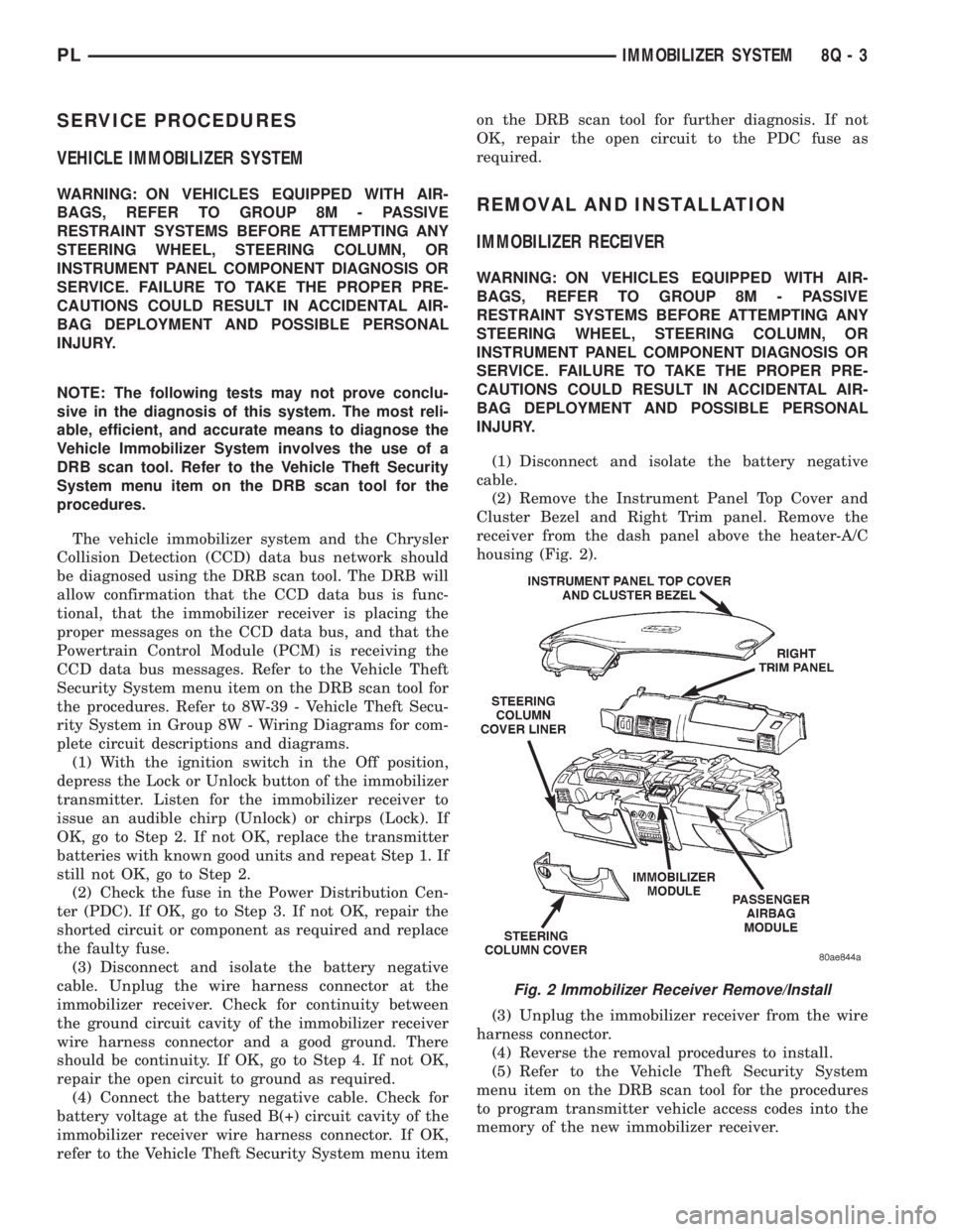
housing (Fig. 2).
(3) Unplug the immobilizer receiver from the wire
harness connector.
(4) Reverse the removal procedures to install.
(5) Refer to the Vehicle Theft Security System
menu item on the DRB scan tool for the procedures
to program transmitter vehicle access codes into the
memory of the new immobilizer receiver.
Fig. 2 Immobilizer Receiver Remove/Install
PLIMMOBILIZER SYSTEM 8Q - 3
Page 381 of 1200
(7) It is necessary that the window be free to slide
up and down in the glass channels. If the window is
not free to move up and down, the window lift motor
will not be able to move the glass.
(8) To determine if the glass is free, disconnect the
regulator from the glass lift plate. Remove the two
attaching nuts, and slide the window up and down by
hand. This check can not be made on a four door
vehicle.
REMOVAL AND INSTALLATION
WINDOW SWITCH
REMOVAL
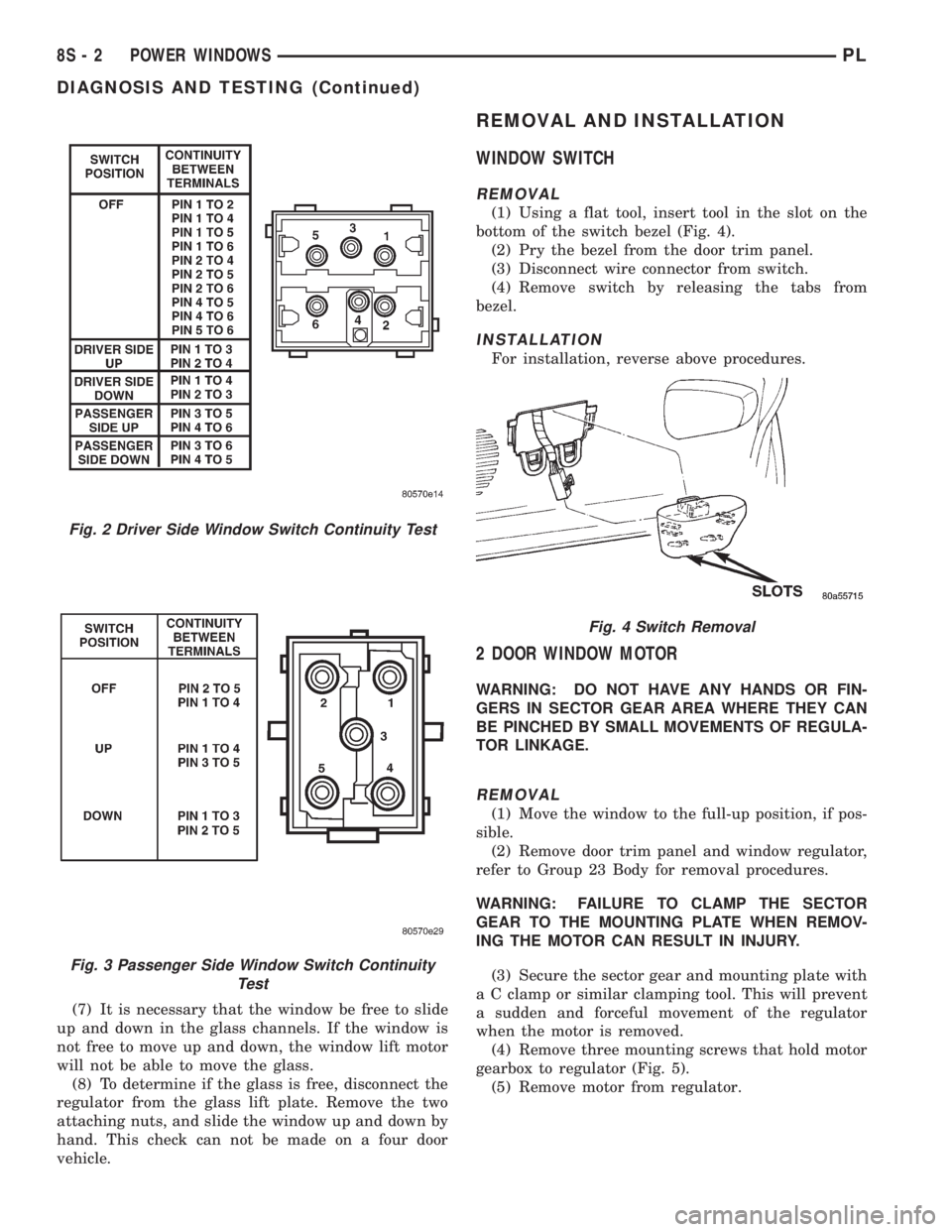
(1) Using a flat tool, insert tool in the slot on the
bottom of the switch bezel (Fig. 4).
(2) Pry the bezel from the door trim panel.
(3) Disconnect wire connector from switch.
(4) Remove switch by releasing the tabs from
bezel.
INSTALLATION
For installation, reverse above procedures.
2 DOOR WINDOW MOTOR
WARNING: DO NOT HAVE ANY HANDS OR FIN-
GERS IN SECTOR GEAR AREA WHERE THEY CAN
BE PINCHED BY SMALL MOVEMENTS OF REGULA-
TOR LINKAGE.
REMOVAL
(1) Move the window to the full-up position, if pos-
sible.
(2) Remove door trim panel and window regulator,
refer to Group 23 Body for removal procedures.
WARNING: FAILURE TO CLAMP THE SECTOR
GEAR TO THE MOUNTING PLATE WHEN REMOV-
ING THE MOTOR CAN RESULT IN INJURY.
(3) Secure the sector gear and mounting plate with
a C clamp or similar clamping tool. This will prevent
a sudden and forceful movement of the regulator
when the motor is removed.
(4) Remove three mounting screws that hold motor
gearbox to regulator (Fig. 5).
(5) Remove motor from regulator.
Fig. 2 Driver Side Window Switch Continuity Test
Fig. 3 Passenger Side Window Switch Continuity
Test
Fig. 4 Switch Removal
8S - 2 POWER WINDOWSPL
DIAGNOSIS AND TESTING (Continued)
Page 390 of 1200
CHIME WARNING/REMINDER SYSTEM
CONTENTS
page page
GENERAL INFORMATION
INTRODUCTION......................... 1
DIAGNOSIS AND TESTING
CHIME SYSTEM CONDITIONS.............. 1
FASTEN SEAT BELTS..................... 1
HEADLAMPS LEFT ON.................... 1KEY LEFT IN IGNITION SWITCH............ 1
REMOVAL AND INSTALLATION
CHIME................................. 2
HEADLAMP SWITCH..................... 2
KEY-IN SWITCH......................... 2
SEAT BELT BUCKLE...................... 2
GENERAL INFORMATION
INTRODUCTION
WARNING: ON VEHICLES EQUIPPED WITH AN
AIRBAG, REFER TO THE AIRBAG PORTION OF
THIS SECTION FOR STEERING WHEEL OR SWITCH
REMOVAL AND INSTALLATION PROCEDURES.
The seat belt reminder system uses both visual
and audible signals. A combined seat belt and key
reminder chime with a red light on the instrument
panel.
The system will always illuminate the seat belt
reminder lamp for four to eight seconds when the
ignition switch is turned to the ON position. The
CHIME will sound during the same time interval if
the driver's seat belt is not fastened. Passenger belts
are not connected to the system. The chime will acti-
vate if the drivers door is opened and:
²The key is in the ignition switch, with the igni-
tion switch in either the OFF or accessory (ACC)
position
²The head lamps are ON.
The chime is part of the instrument cluster.
NOTE: This group covers both Left-Hand Drive
(LHD) and Right-Hand Drive (RHD) versions of this
model. Whenever required and feasible, the RHD
versions of affected vehicle components have been
constructed as mirror-image of the LHD versions.
While most of the illustrations used in this group
represent only the LHD version, the diagnostic and
service procedures outlined can generally be
applied to either version. Exceptions to this rule
have been clearly identified as LHD, RHD, or Export
if a special illustration or procedure is required.
DIAGNOSIS AND TESTING
FASTEN SEAT BELTS
To test the fasten seat belts function, turn the igni-
tion switch to the ON position with the driver's seat
belt unbuckled and fully retracted. The seat belt
warning lamp should light for four to eight seconds
and the tone should sound three to five times.
HEADLAMPS LEFT ON
To test the headlamps left on function:
²Turn headlamps
²Driver's door open
²Key removed from the ignition switch
Chime should sound until headlamps are turned
off or driver's door is closed.
KEY LEFT IN IGNITION SWITCH
To test the key left in ignition function, insert key
into the ignition and open driver's door. Chime
should sound until key is removed from ignition or
driver's door is closed.
CHIME SYSTEM CONDITIONS
The cluster harness connector, J1 is car right and
the J2 is car left.
NO TONE WHEN IGNITION SWITCH IS
TURNED ON AND DRIVERS SEAT BELT IS
UNBUCKLED
(1) Using an ohmmeter, with the seat belt fully
retracted, check for continuity to ground at Pin 4 of
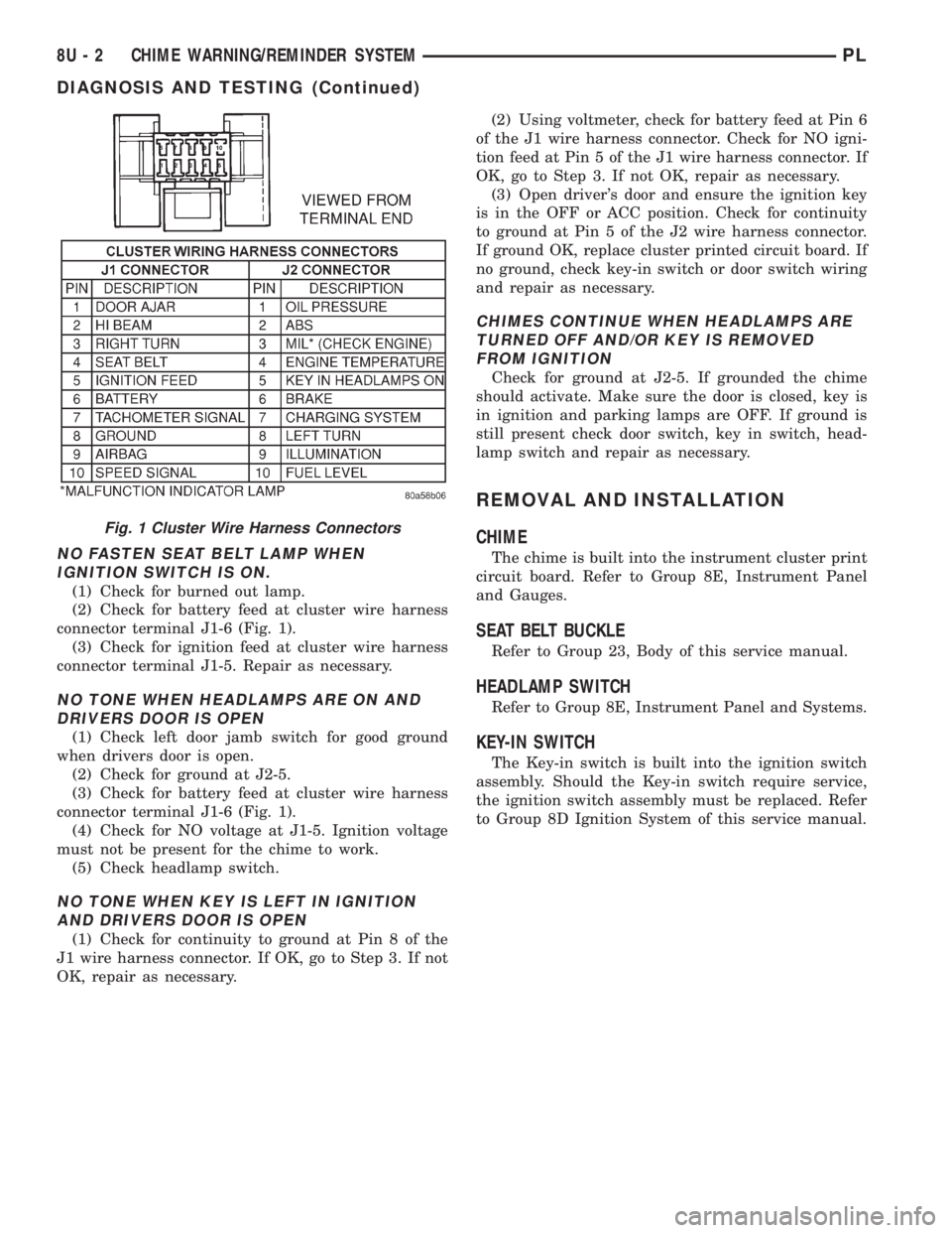
the J1 wire harness connector (Fig. 1). If OK, go to
step 2. If not OK, repair as necessary .
(2) Check for continuity to ground at Pin 8 of the
J1 wire harness connector. If OK, go to Step 3. If not
OK, repair as necessary.
(3) Using voltmeter, check for battery feed at Pin 6
of the J1 wire harness connector. Check for ignition
feed at Pin 5 of the J1 wire harness connector. If not
OK, repair as necessary.
PLCHIME WARNING/REMINDER SYSTEM 8U - 1
Page 391 of 1200
NO FASTEN SEAT BELT LAMP WHEN
IGNITION SWITCH IS ON.
(1) Check for burned out lamp.
(2) Check for battery feed at cluster wire harness
connector terminal J1-6 (Fig. 1).
(3) Check for ignition feed at cluster wire harness
connector terminal J1-5. Repair as necessary.
NO TONE WHEN HEADLAMPS ARE ON AND
DRIVERS DOOR IS OPEN
(1) Check left door jamb switch for good ground
when drivers door is open.
(2) Check for ground at J2-5.
(3) Check for battery feed at cluster wire harness
connector terminal J1-6 (Fig. 1).
(4) Check for NO voltage at J1-5. Ignition voltage
must not be present for the chime to work.
(5) Check headlamp switch.
NO TONE WHEN KEY IS LEFT IN IGNITION
AND DRIVERS DOOR IS OPEN
(1) Check for continuity to ground at Pin 8 of the
J1 wire harness connector. If OK, go to Step 3. If not
OK, repair as necessary.(2) Using voltmeter, check for battery feed at Pin 6
of the J1 wire harness connector. Check for NO igni-
tion feed at Pin 5 of the J1 wire harness connector. If
OK, go to Step 3. If not OK, repair as necessary.
(3) Open driver's door and ensure the ignition key
is in the OFF or ACC position. Check for continuity
to ground at Pin 5 of the J2 wire harness connector.
If ground OK, replace cluster printed circuit board. If
no ground, check key-in switch or door switch wiring
and repair as necessary.
CHIMES CONTINUE WHEN HEADLAMPS ARE
TURNED OFF AND/OR KEY IS REMOVED
FROM IGNITION
Check for ground at J2-5. If grounded the chime
should activate. Make sure the door is closed, key is
in ignition and parking lamps are OFF. If ground is
still present check door switch, key in switch, head-
lamp switch and repair as necessary.
REMOVAL AND INSTALLATION
CHIME
The chime is built into the instrument cluster print
circuit board. Refer to Group 8E, Instrument Panel
and Gauges.
SEAT BELT BUCKLE
Refer to Group 23, Body of this service manual.
HEADLAMP SWITCH
Refer to Group 8E, Instrument Panel and Systems.
KEY-IN SWITCH
The Key-in switch is built into the ignition switch
assembly. Should the Key-in switch require service,
the ignition switch assembly must be replaced. Refer
to Group 8D Ignition System of this service manual.
Fig. 1 Cluster Wire Harness Connectors
8U - 2 CHIME WARNING/REMINDER SYSTEMPL
DIAGNOSIS AND TESTING (Continued)
Page 394 of 1200
8W-01 GENERAL INFORMATION
INDEX
page page
DESCRIPTION AND OPERATION
CIRCUIT FUNCTIONS..................... 4
CIRCUIT INFORMATION................... 4
CONNECTOR INFORMATION............... 7
ELECTROSTATIC DISCHARGE (ESD)
SENSITIVE DEVICES.................... 8
INTRODUCTION......................... 1
NOTES, CAUTIONS, and WARNINGS......... 7
SECTION IDENTIFICATION................. 5
SPLICE LOCATIONS...................... 7
SYMBOLS.............................. 5
TAKE OUTS............................. 8
TERMINOLOGY.......................... 7
DIAGNOSIS AND TESTING
INTERMITTENT AND POOR CONNECTIONS.... 9TROUBLESHOOTING TESTS................ 9
TROUBLESHOOTING TOOLS............... 8
TROUBLESHOOTING WIRING PROBLEMS.... 10
SERVICE PROCEDURES
CONNECTOR AND TERMINAL REPLACEMENT . 12
CONNECTOR REPLACEMENT.............. 12
DIODE REPLACEMENT................... 14
TERMINAL REPLACEMENT................ 13
TERMINAL/CONNECTOR REPAIR-MOLEX
CONNECTORS........................ 10
TERMINAL/CONNECTOR REPAIRÐTHOMAS
AND BETTS CONNECTORS.............. 11
WIRING REPAIR........................ 10
SPECIAL TOOLS
WIRING/TERMINAL...................... 15
DESCRIPTION AND OPERATION
INTRODUCTION
Chrysler wiring diagrams are designed to provide
information regarding the vehicles wiring content. In
order to effectively use Chrysler wiring diagrams to
diagnose and repair a Chrysler vehicle, it is impor-
tant to understand all of their features and charac-
teristics.
Diagrams are arranged such that the power (B+)
side of the circuit is placed near the top of the page,
and the ground (B-) side of the circuit is placed near
the bottom of the page.
All switches, components, and modules are shown
in the at rest position with the doors closed and the
key removed from the ignition.Components are shown two ways. A solid line
around a component indicates that the component is
complete. A dashed line around a component indi-
cates that the component being shown is not com-
plete. Incomplete components have a reference
number to indicate the page where the component is
shown complete.
It is important to realize that no attempt is made
on the diagrams to represent components and wiring
as they appear on the vehicle. For example, a short
piece of wire is treated the same as a long one. In
addition, switches and other components are shown
as simply as possible, with regard to function only.
PL8W - 01 GENERAL INFORMATION 8W - 01 - 1
Page 400 of 1200
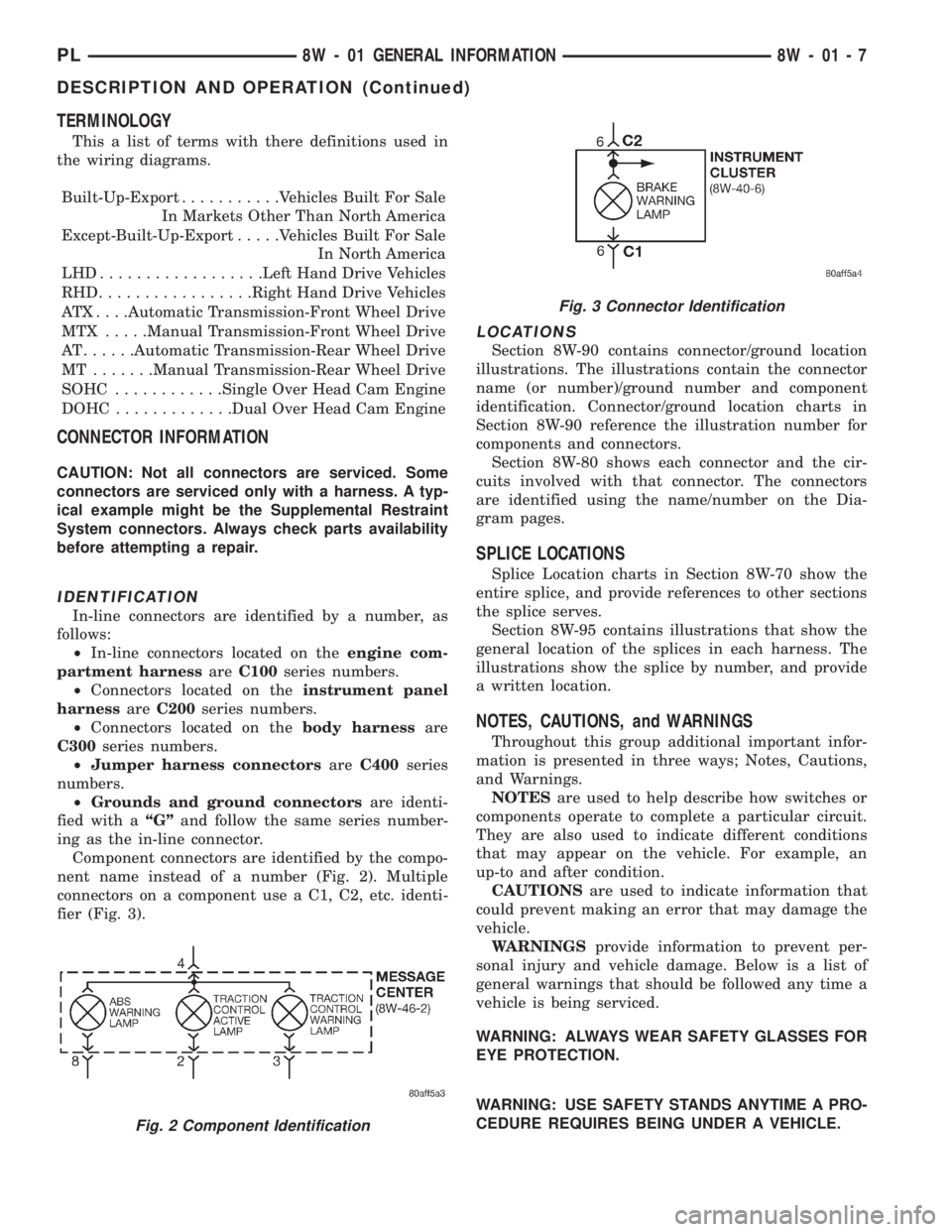
TERMINOLOGY
This a list of terms with there definitions used in
the wiring diagrams.
Built-Up-Export...........Vehicles Built For Sale
In Markets Other Than North America
Except-Built-Up-Export.....Vehicles Built For Sale
In North America
LHD..................Left Hand Drive Vehicles
RHD.................Right Hand Drive Vehicles
ATX . . . .Automatic Transmission-Front Wheel Drive
MTX .....Manual Transmission-Front Wheel Drive
AT......Automatic Transmission-Rear Wheel Drive
MT .......Manual Transmission-Rear Wheel Drive
SOHC............Single Over Head Cam Engine
DOHC.............Dual Over Head Cam Engine
CONNECTOR INFORMATION
CAUTION: Not all connectors are serviced. Some
connectors are serviced only with a harness. A typ-
ical example might be the Supplemental Restraint
System connectors. Always check parts availability
before attempting a repair.
IDENTIFICATION
In-line connectors are identified by a number, as
follows:
²In-line connectors located on theengine com-
partment harnessareC100series numbers.
²Connectors located on theinstrument panel
harnessareC200series numbers.
²Connectors located on thebody harnessare
C300series numbers.
²Jumper harness connectorsareC400series
numbers.
²Grounds and ground connectorsare identi-
fied with aªGºand follow the same series number-
ing as the in-line connector.
Component connectors are identified by the compo-
nent name instead of a number (Fig. 2). Multiple
connectors on a component use a C1, C2, etc. identi-
fier (Fig. 3).
LOCATIONS
Section 8W-90 contains connector/ground location
illustrations. The illustrations contain the connector
name (or number)/ground number and component
identification. Connector/ground location charts in
Section 8W-90 reference the illustration number for
components and connectors.
Section 8W-80 shows each connector and the cir-
cuits involved with that connector. The connectors
are identified using the name/number on the Dia-
gram pages.
SPLICE LOCATIONS
Splice Location charts in Section 8W-70 show the
entire splice, and provide references to other sections
the splice serves.
Section 8W-95 contains illustrations that show the
general location of the splices in each harness. The
illustrations show the splice by number, and provide
a written location.
NOTES, CAUTIONS, and WARNINGS
Throughout this group additional important infor-
mation is presented in three ways; Notes, Cautions,
and Warnings.
NOTESare used to help describe how switches or
components operate to complete a particular circuit.
They are also used to indicate different conditions
that may appear on the vehicle. For example, an
up-to and after condition.
CAUTIONSare used to indicate information that
could prevent making an error that may damage the
vehicle.
WARNINGSprovide information to prevent per-
sonal injury and vehicle damage. Below is a list of
general warnings that should be followed any time a
vehicle is being serviced.
WARNING: ALWAYS WEAR SAFETY GLASSES FOR
EYE PROTECTION.
WARNING: USE SAFETY STANDS ANYTIME A PRO-
CEDURE REQUIRES BEING UNDER A VEHICLE.
Fig. 2 Component Identification
Fig. 3 Connector Identification
PL8W - 01 GENERAL INFORMATION 8W - 01 - 7
DESCRIPTION AND OPERATION (Continued)
Page 401 of 1200
WARNING: BE SURE THAT THE IGNITION SWITCH
ALWAYS IS IN THE OFF POSITION, UNLESS THE
PROCEDURE REQUIRES IT TO BE ON.
WARNING: SET THE PARKING BRAKE WHEN
WORKING ON ANY VEHICLE. AN AUTOMATIC
TRANSMISSION SHOULD BE IN PARK. A MANUAL
TRANSMISSION SHOULD BE IN NEUTRAL.
WARNING: OPERATE THE ENGINE ONLY IN A
WELL-VENTILATED AREA.
WARNING: KEEP AWAY FROM MOVING PARTS
WHEN THE ENGINE IS RUNNING, ESPECIALLY THE
FAN AND BELTS.
WARNING: TO PREVENT SERIOUS BURNS, AVOID
CONTACT WITH HOT PARTS SUCH AS THE RADIA-
TOR, EXHAUST MANIFOLD(S), TAIL PIPE, CATA-
LYTIC CONVERTER, AND MUFFLER.
WARNING: DO NOT ALLOW FLAME OR SPARKS
NEAR THE BATTERY. GASES ARE ALWAYS
PRESENT IN AND AROUND THE BATTERY.
WARNING: ALWAYS REMOVE RINGS, WATCHES,
LOOSE HANGING JEWELRY, AND LOOSE CLOTH-
ING.
TAKE OUTS
The abbreviation T/O is used in the component
location section to indicate a point in which the wir-
ing harness branches out to a component.
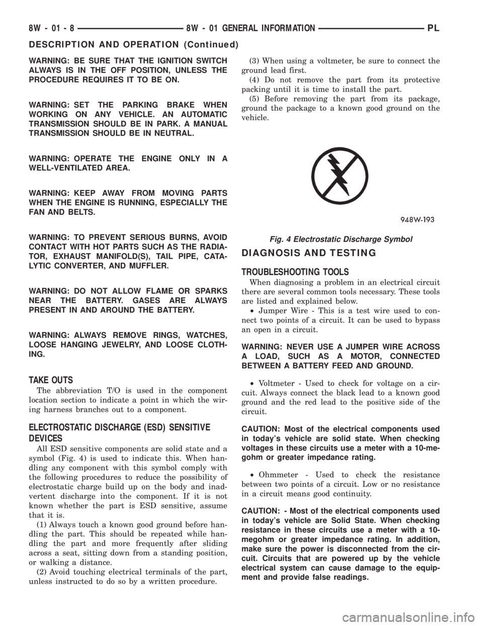
ELECTROSTATIC DISCHARGE (ESD) SENSITIVE
DEVICES
All ESD sensitive components are solid state and a
symbol (Fig. 4) is used to indicate this. When han-
dling any component with this symbol comply with
the following procedures to reduce the possibility of
electrostatic charge build up on the body and inad-
vertent discharge into the component. If it is not
known whether the part is ESD sensitive, assume
that it is.
(1) Always touch a known good ground before han-
dling the part. This should be repeated while han-
dling the part and more frequently after sliding
across a seat, sitting down from a standing position,
or walking a distance.
(2) Avoid touching electrical terminals of the part,
unless instructed to do so by a written procedure.(3) When using a voltmeter, be sure to connect the
ground lead first.
(4) Do not remove the part from its protective
packing until it is time to install the part.
(5) Before removing the part from its package,
ground the package to a known good ground on the
vehicle.
DIAGNOSIS AND TESTING
TROUBLESHOOTING TOOLS
When diagnosing a problem in an electrical circuit
there are several common tools necessary. These tools
are listed and explained below.
²Jumper Wire - This is a test wire used to con-
nect two points of a circuit. It can be used to bypass
an open in a circuit.
WARNING: NEVER USE A JUMPER WIRE ACROSS
A LOAD, SUCH AS A MOTOR, CONNECTED
BETWEEN A BATTERY FEED AND GROUND.
²Voltmeter - Used to check for voltage on a cir-
cuit. Always connect the black lead to a known good
ground and the red lead to the positive side of the
circuit.
CAUTION: Most of the electrical components used
in today's vehicle are solid state. When checking
voltages in these circuits use a meter with a 10-me-
gohm or greater impedance rating.
²Ohmmeter - Used to check the resistance
between two points of a circuit. Low or no resistance
in a circuit means good continuity.
CAUTION: - Most of the electrical components used
in today's vehicle are Solid State. When checking
resistance in these circuits use a meter with a 10-
megohm or greater impedance rating. In addition,
make sure the power is disconnected from the cir-
cuit. Circuits that are powered up by the vehicle
electrical system can cause damage to the equip-
ment and provide false readings.
Fig. 4 Electrostatic Discharge Symbol
8W - 01 - 8 8W - 01 GENERAL INFORMATIONPL
DESCRIPTION AND OPERATION (Continued)
Page 410 of 1200

8W-02 COMPONENT INDEX
Component Page
A/C Compressor Clutch..................8W-42
A/C Compressor Clutch Relay.............8W-42
A/C Cycling Switch.....................8W-42
A/C Heater Blower Motor................8W-42
A/C Heater Control.....................8W-42
A/C Pressure Switches...................8W-42
ABS Warning Lamp Relay................8W-35
Airbag Control Module...................8W-43
Airbags..............................8W-43
Antenna..............................8W-47
Ash Receiver Lamp.....................8W-44
Automatic Shut Down Relay..............8W-30
Back-Up Lamp Switch...................8W-51
Back-Up Lamps........................8W-51
Battery..............................8W-20
Battery Temperature Sensor..............8W-30
Blower Motor Resistor Block..............8W-42
Brake Warning Lamp Switch...........8W-40, 50
Camshaft Position Sensor................8W-30
Center High Mounted Stop Lamp..........8W-51
Cigar Lighter Relay.....................8W-41
Cigar Lighter/Power Outlet...............8W-41
Circuit Breakers.......................8W-11
Clockspring.....................8W-30, 41, 61
Clutch Pedal Position Switch...........8W-10, 21
Combination Flasher....................8W-52
Controller Anti-Lock Brake...............8W-35
Crankshaft Position Sensor...............8W-30
Data Link Connector....................8W-30
Daytime Running Lamp Module...........8W-50
Diode No. 1........................8W-15, 42
Diode No. 2......................8W-10, 11, 44
Diode No. 3......................8W-11,44,70
Dome Lamp...........................8W-44
Door Ajar Switches.....................8W-44
Door Jamb Switches....................8W-44
Door Lock Motors......................8W-61
Door Lock Motors......................8W-61
Door Lock Switches.....................8W-61
Duty Cycle Evap/Purge Solenoid...........8W-30
EGR Transducer Solenoid................8W-30
Engine Coolant Temperature Sensor........8W-30
Engine Oil Pressure Switch...............8W-40
Engine Starter Motor....................8W-21
Engine Starter Motor Relay...............8W-21
Fog Lamp Relays....................8W-50, 51
Fog Lamp Switches..................8W-50, 51
Fog Lamps.........................8W-50, 51
Fuel Injectors..........................8W-30
Fuel Pump Module.....................8W-30
Fuel Pump Relay.......................8W-30
Fuse Block............................8W-11Component Page
Fuses (FB)............................8W-11
Fuses (PDC)...........................8W-10
Fusible Link........................8W-20, 21
Generator.............................8W-20
Glove Box Lamp And Switch..............8W-44
Grounds..............................8W-15
Halo Lamp............................8W-44
Headlamp Dimmer And Optical Horn Switch .8W-50
Headlamp Leveling Motors...............8W-50
Headlamp Leveling Switch...............8W-50
Headlamp Switch.......................8W-50
Headlamps............................8W-50
High Speed Warning Module..............8W-40
Horn Relay...........................8W-41
Horn Switches.........................8W-41
Horns................................8W-41
IAT/Map Sensor........................8W-30
Idle Air Control Motor...................8W-30
Ignition Coil Pack......................8W-30
Ignition Switch........................8W-10
Illumination Lamps.....................8W-40
Immobilizer...........................8W-61
Immobilizer Engine Sensor............8W-30, 61
Indicator Lamps........................8W-40
Instrument Cluster.....................8W-40
Intermittent Wipe/Wash Switch............8W-53
Key-In Switch.........................8W-40
Knock Sensor..........................8W-30
License Lamps.........................8W-51
Map/Reading Lamps....................8W-44
Noise Supressor.....................8W-10, 30
Oxygen Sensors........................8W-30
Park Brake Switch...................8W-40, 50
Park/Neutral Position Switch...........8W-30, 51
Park/Turn Signal Lamps..............8W-50, 52
Power Distribution Center................8W-10
Power Folding Mirror Relay...............8W-62
Power Mirror Fuse Holder................8W-62
Power Mirrors.........................8W-62
Power Steering Pressure Switch...........8W-30
Power Sunroof Motor....................8W-64
Power Window Motors...................8W-60
Power Window Switches.................8W-60
Powertrain Control Module...............8W-30
PRNDL Lamp.........................8W-44
Radiator Fan Motor.....................8W-42
Radio................................8W-47
Rear Window Defogger..................8W-48
Rear Window Defogger Switch.............8W-48
Remote Keyless Entry Module.............8W-61
Remote Keyless Entry Program
Module Connector....................8W-61
PL8W - 02 COMPONENT INDEX 8W - 02 - 1