1999 DODGE NEON diagram
[x] Cancel search: diagramPage 107 of 1200
Place gauge (Form A) on edge over end of brake
tubing. Push tubing through jaws until end of tubing
contacts the recessed notch in gauge matching the
tubing size. Squeeze handles of flaring tool and lock
tubing in place. Place 3/16 inch plug of gauge (A)
down in end of tubing. Swing compression disc over
gauge and center tapered flaring screw in recess of
disc. Screw in until plug gauge has seated on jaws of
flaring tool. This action has started to invert the
extended end of the tubing. Remove gauge and con-
tinue to screw down until tool is firmly seated in tub-
ing. Remove tubing from flaring tool and inspect
seat. Refer to tube routing diagrams for proper brake
tube routing and clip locations. Replace any damaged
tube routing clips.
REMOVAL AND INSTALLATION
WHEEL AND TIRE ASSEMBLY
To install the wheel and tire assembly, first posi-
tion it properly on the mounting surface using the
hub pilot as a guide. Then progressively tighten the
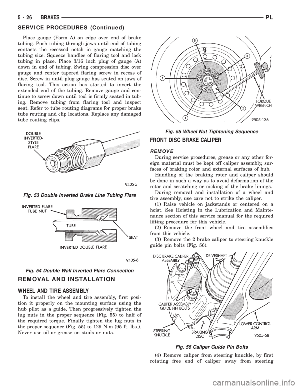
lug nuts in the proper sequence (Fig. 55) to half of
the required torque. Finally tighten the lug nuts in
the proper sequence (Fig. 55) to 129 N´m (95 ft. lbs.).
Never use oil or grease on studs or nuts.
FRONT DISC BRAKE CALIPER
REMOVE
During service procedures, grease or any other for-
eign material must be kept off caliper assembly, sur-
faces of braking rotor and external surfaces of hub.
Handling of the braking rotor and caliper should
be done in such a way as to avoid deformation of the
rotor and scratching or nicking of the brake linings.
During removal and installation of a wheel and
tire assembly, use care not to strike the caliper.
(1) Raise vehicle on jackstands or centered on a
hoist. See Hoisting in the Lubrication and Mainte-
nance section of this service manual for the required
lifting procedure for this vehicle.
(2) Remove the front wheel and tire assemblies
from this vehicle.
(3) Remove the 2 brake caliper to steering knuckle
guide pin bolts (Fig. 56).
(4) Remove caliper from steering knuckle, by first
rotating free end of caliper away from steering
Fig. 53 Double Inverted Brake Line Tubing Flare
Fig. 54 Double Wall Inverted Flare Connection
Fig. 55 Wheel Nut Tightening Sequence
Fig. 56 Caliper Guide Pin Bolts
5 - 26 BRAKESPL
SERVICE PROCEDURES (Continued)
Page 150 of 1200
ANTILOCK BRAKE SYSTEM±TEVES MARK 20
INDEX
page page
DESCRIPTION AND OPERATION
ABS BRAKE SYSTEM COMPONENTS........ 71
ABS BRAKES OPERATION AND VEHICLE
PERFORMANCE....................... 69
ABS COMPONENT ABBREVIATION LIST...... 69
ABS FLUID ACCUMULATORS.............. 72
ABS FUSES............................ 73
ABS MASTER CYLINDER AND POWER BRAKE
BOOSTER............................ 71
ABS RELAYS........................... 73
ABS WARNING LAMP (YELLOW)............ 75
ANTILOCK BRAKES OPERATION
DESCRIPTION........................ 69
CONTROLLER ANTILOCK BRAKES (CAB)..... 74
HCU PUMP/MOTOR..................... 72
HYDRAULIC CIRCUITS AND VALVE
OPERATION.......................... 75
INLET VALVES AND SOLENOIDS............ 72
INTEGRATED CONTROL UNIT (ICU)......... 71
OUTLET VALVES AND SOLENOIDS.......... 72
PROPORTIONING VALVE................. 73
WHEEL SPEED SENSORS................. 73
DIAGNOSIS AND TESTING
ABS DIAGNOSTIC TROUBLE CODES........ 78
ABS DIAGNOSTICS MANUAL.............. 76
ABS GENERAL DIAGNOSTICS INFORMATION . 75
ABS SERVICE PRECAUTIONS.............. 76
ABS SYSTEM SELF DIAGNOSTICS.......... 77ABS WIRING DIAGRAM INFORMATION....... 76
BRAKE FLUID CONTAMINATION............ 80
DRB DIAGNOSTIC CONNECTOR............ 77
DRB DIAGNOSTIC SCAN TOOL USAGE...... 77
INTERMITTENT DIAGNOSTIC TROUBLE
CODES.............................. 78
PROPORTIONING VALVE................. 79
TEST DRIVING ABS COMPLAINT VEHICLE.... 80
TONEWHEEL INSPECTION................ 79
SERVICE PROCEDURES
BLEEDING TEVES MARK 20 HYDRAULIC
SYSTEM............................. 81
BRAKE FLUID LEVEL INSPECTION.......... 80
REMOVAL AND INSTALLATION
ABS GENERAL SERVICE PRECAUTIONS..... 81
ABS HYDRAULIC CONTROL UNIT........... 82
CONTROLLER ANTILOCK BRAKES (CAB)..... 86
FRONT WHEEL SPEED SENSOR........... 87
MASTER CYLINDER AND POWER BRAKE
BOOSTER............................ 86
PROPORTIONING VALVES................ 86
REAR WHEEL SPEED SENSOR............ 88
SPECIFICATIONS
BRAKE FASTENER TORQUE SPECIFICATIONS . 89
SPEED SENSOR TONE WHEEL RUNOUT..... 89
WHEEL SPEED SENSOR TO TONE WHEEL
CLEARANCE.......................... 89
DESCRIPTION AND OPERATION
ANTILOCK BRAKES OPERATION DESCRIPTION
The purpose of an Antilock Brake System (ABS) is
to prevent wheel lock-up under braking conditions on
virtually any type of road surface. Antilock Braking
is desirable because a vehicle which is stopped with-
out locking the wheels will retain directional stability
and some steering capability. This allows the driver
to retain greater control of the vehicle during brak-
ing.
This section of the service manual covers the
description and on car service for the ITT Teves
Mark 20 ABS Brake System. If other service is
required on the non ABS related components of the
brake system, refer to the appropriate section in this
group of the service manual for the specific service
procedure required.
ABS COMPONENT ABBREVIATION LIST
In this section of the service manual, several
abbreviations are used for the components of the
Teves Mark 20 ABS Brake System. They are listed
below for your reference.
²CAB±Controller Antilock Brake
²ICU±Integrated Control Unit
²HCU±Hydraulic Control Unit
²ABS±Antilock Brake System
²PSI±Pounds Per Square Inch (pressure)
²WSS±Wheel Speed Sensor
²FWD±Front Wheel Drive
²DTC±Diagnostic Trouble Code
ABS BRAKES OPERATION AND VEHICLE
PERFORMANCE
This ABS System represents the current state-of-
the-art in vehicle braking systems and offers the
driver increased safety and control during braking.
PLBRAKES 5 - 69
Page 156 of 1200
cally cleared from the CAB memory after the identi-
cal fault has not been seen during the next 255 key
cycles of vehicle operation.
CONTROLLER ANTILOCK BRAKE INPUTS
²Four wheel speed sensors.
²Stop lamp switch.
²Ignition switch.
²System relay voltage.
²Ground.
²Diagnostics Communications (CCD)
CONTROLLER ANTILOCK BRAKE OUTPUTS
²ABS warning lamp actuation.
²Diagnostic communication. (CCD)
ABS WARNING LAMP (YELLOW)
The ABS system uses a yellow colored ABS Warn-
ing Lamp. The ABS warning lamp is located on the
lower left side of the instrument pane. The purpose
of the warning lamp is discussed in detail below.
The ABS warning lamp will turn on when the CAB
detects a condition which results in a shutdown of
ABS function. When the ignition key is turned to the
on position, the ABS Warning Lamp is on until the
CAB completes its self tests and turns the lamp off
(approximately 4 seconds after the ignition switch is
turned on). Under most conditions, when the ABS
warning lamp is on, only the ABS function of the
brake system is affected. The standard brake system
and the ability to stop the car will not be affected
when only the ABS warning lamp is on.
The ABS warning lamp is controlled by the CAB.
The CAB turns on the yellow ABS warning lamp by
grounding the circuit.
HYDRAULIC CIRCUITS AND VALVE OPERATION
Through the following operation descriptions the
function of the various hydraulic control valves in the
ABS will be described. The fluid control valves men-
tioned below, control the flow of pressurized brake
fluid to the wheel brakes during the different modes
of ABS braking.
For explanation purposes, all wheel speed sensors
except the right front are sending the same wheel
speed information. The following diagrams show only
the right front wheel in a antilock braking condition.
NORMAL BRAKING HYDRAULIC CIRCUIT AND
SOLENOID VALVE FUNCTION
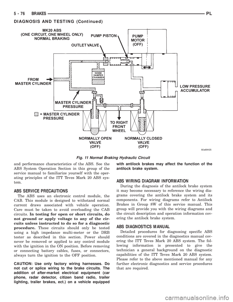
This condition is the normal operation of the vehi-
cles base brake hydraulic system. The hydraulic sys-
tem circuit diagram (Fig. 11) shows a situation where
no wheel spin or slip is occurring relative to the
speed of the vehicle. The driver is applying the brake
pedal to build pressure in the brake hydraulic system
to apply the brakes and stop the vehicle.
TEVES MARK 20 ABS CIRCUIT AND
SOLENOID VALVE FUNCTION
This hydraulic circuit diagram (Fig. 12) shows the
vehicle in the ABS braking mode. This hydraulic cir-
cuit (Fig. 12) shows a situation where one wheel is
slipping because the driver is attempting to stop the
vehicle at a faster rate than the surface the vehicle's
tires are on will allow. The normally open and nor-
mally closed valves modulate the brake hydraulic
pressure as required. The pump/motor is switched on
so that the brake fluid from the low pressure accu-
mulators is returned to the master cylinder circuits.
The brake fluid will then be routed to either the mas-
ter cylinder or the wheel brake depending on the
position of the normally open valve.
TEVES MARK 20 SECONDARY ABS CIRCUIT
AND SOLENOID VALVE FUNCTION
This hydraulic circuit diagram (Fig. 13) shows the
vehicle in the ABS braking mode. This hydraulic cir-
cuit (Fig. 13) shows a situation where one wheel is
slipping because the driver is attempting to stop the
vehicle at a faster rate than the surface the vehicle's
tires are on will allow. The normally open and nor-
mally closed valves modulate the brake hydraulic
pressure as required. The pump/motor is switched on
so that the brake fluid from the low pressure accu-
mulators is returned to the master cylinder circuits.
The brake fluid will then be routed to either the mas-
ter cylinder or the wheel brake depending on the
position of the normally open valve. A volume of 1.2
cc's of brake fluid is taken in by the lip seal saver
(Fig. 13) to protect the lip seals on the piston of the
master cylinder.
DIAGNOSIS AND TESTING
ABS GENERAL DIAGNOSTICS INFORMATION
This section contains the information necessary to
diagnose the ITT Teves Mark 20 ABS Brake System.
Specifically, this section should be used to help diag-
nose conditions which result in any of the following:
(1) ABS Warning Lamp turned on.
(2) Brakes Lock-up on hard application
Diagnosis of base brake conditions which are obvi-
ously mechanical in nature should be directed to
Group 5 Brakes in this service manual. This includes
brake noise, brake pulsation, lack of power assist,
parking brake, Red BRAKE Warning Lamp lighting,
or vehicle vibration during normal braking.
Many conditions that generate customer com-
plaints may be normal operating conditions, but are
judged to be a problem due to not being familiar with
the ABS system. These conditions can be recognized
without performing extensive diagnostic work, given
adequate understanding of the operating principles
PLBRAKES 5 - 75
DESCRIPTION AND OPERATION (Continued)
Page 157 of 1200
and performance characteristics of the ABS. See the
ABS System Operation Section in this group of the
service manual to familiarize yourself with the oper-
ating principles of the ITT Teves Mark 20 ABS sys-
tem.
ABS SERVICE PRECAUTIONS
The ABS uses an electronic control module, the
CAB. This module is designed to withstand normal
current draws associated with vehicle operation.
Care must be taken to avoid overloading the CAB
circuits.In testing for open or short circuits, do
not ground or apply voltage to any of the cir-
cuits unless instructed to do so for a diagnostic
procedure.These circuits should only be tested
using a high impedance multi-meter or the DRB
tester as described in this section. Power should
never be removed or applied to any control module
with the ignition in the ON position. Before removing
or connecting battery cables, fuses, or connectors,
always turn the ignition to the OFF position.
CAUTION: Use only factory wiring harnesses. Do
not cut or splice wiring to the brake circuits. The
addition of after-market electrical equipment (car
phone, radar detector, citizen band radio, trailer
lighting, trailer brakes, ect.) on a vehicle equippedwith antilock brakes may affect the function of the
antilock brake system.
ABS WIRING DIAGRAM INFORMATION
During the diagnosis of the antilock brake system
it may become necessary to reference the wiring dia-
grams covering the antilock brake system and its
components. For wiring diagrams refer to Antilock
Brakes in Group 8W of this service manual. This
group will provide you with the wiring diagrams and
the circuit description and operation information cov-
ering the antilock brake system.
ABS DIAGNOSTICS MANUAL
Detailed procedures for diagnosing specific ABS
conditions are covered in the diagnostics manual cov-
ering the ITT Teves Mark 20 ABS system. The fol-
lowing information is presented to give the
technician a general background on the diagnostic
capabilities of the ITT Teves Mark 20 ABS system.
Please refer to the above mentioned manual for any
further electronic diagnostics and service procedures
that are required.
Fig. 11 Normal Braking Hydraulic Circuit
5 - 76 BRAKESPL
DIAGNOSIS AND TESTING (Continued)
Page 160 of 1200
A visual inspection for loose, disconnected, or mis-
routed wires should be done before attempting to
diagnose or service the ITT Teves Mark 20 antilock
brake system. A visual inspection will eliminate
unnecessary testing and diagnostics time. A thorough
visual inspection will include the following compo-
nents and areas of the vehicle.
(1) Inspect fuses in the power distribution center
(PDC) and the wiring junction block. Verify that all
fuses are fully inserted into the PDC and wring junc-
tion block. A label on the underside of the PDC cover
identifies the locations of the ABS fuses in the PDC.
(2) Inspect the 25-way electrical connector at the
CAB for damage, spread or backed-out wiring termi-
nals. Verify that the 25-way connector is fully
inserted in the socket on the CAB. Be sure that wires
are not stretched tight or pulled out of the connector.
(3) Verify that all the wheel speed sensor connec-
tions are secure.
(4) Poor mating of connector halves or terminals
not fully seated in the connector body.
(5) Improperly formed or damaged terminals. All
connector terminals in a suspect circuit should be
carefully reformed to increase contact tension.
(6) Poor terminal to wire connection. This requires
removing the terminal from the connector body to
inspect.
(7) Pin presence in the connector assembly
(8) Proper ground connections. Check all ground
connections for signs of corrosion, tight fasteners, or
other potential defects. Refer to wiring diagram man-
ual for ground locations.
(9) Problems with main power sources of the vehi-
cle. Inspect battery, generator, ignition circuits and
other related relays and fuses.
(10) If a visual check does not find the cause of the
problem, operate the car in an attempt to duplicate
the condition and record the trouble code.
(11) Most failures of the ABS system will disable
ABS function for the entire ignition cycle even if the
fault clears before key-off. There are some failure
conditions, however, which will allow ABS operation
to resume during the ignition cycle in which a failure
occurred if the failure conditions are no longer
present. The following conditions may result in inter-
mittent illumination of the ABS Warning Lamp. All
other failures will cause the lamp to remain on until
the ignition switch is turned off. Circuits involving
these inputs to the CAB should be investigated if a
complaint of intermittent warning system operation
is encountered.
(12) Low system voltage. If Low System Voltage is
detected by the CAB, the CAB will turn on the ABS
Warning Lamp until normal system voltage is
achieved. Once normal voltage is seen at the CAB,
normal operation resumes.(13) High system voltage. If high system voltage is
detected by the CAB, the CAB will turn on the
Amber ABS Warning Lamp until normal system volt-
age is achieved. Once normal voltage is again
detected by the CAB, normal ABS operation resumes.
(14) Additionally, any condition which results in
interruption of electrical current to the CAB or mod-
ulator assembly may cause the ABS Warning Lamp
to turn on intermittently.
(15) The body controller can turn on the (yellow)
ABS warning lamp if CCD communication between
the body controller and the CAB is interupted.
TONEWHEEL INSPECTION
CAUTION: The tone wheels used on this vehicle
equipped with the Teves Mark 20 Antilock Brake
System are different then those used on past mod-
els of this vehicle equipped with antilock brakes.
Reduced braking performance will result if this part
is used on earlier model vehicles and an accident
could result. Do not use on pre-1998 model year
vehicles.
Carefully inspect tonewheel at the suspected faulty
wheel speed sensor for missing, chipped or broken
teeth, this can cause erratic speed sensor signals.
Tonewheels should show no evidence of contact
with the wheel speed sensors. If contact was made,
determine cause and correct before replacing the
wheel speed sensor.
Excessive runout of the tonewheel can cause
erratic wheel speed sensor signals. Refer to Tone-
wheel Runout in the Specification Section in this sec-
tion of the service manual for the tonewheel runout
specification. Replace drive shaft assembly or rear
hub/bearing assembly if tonewheel runout exceeds
the specification.
Inspect tonewheels for looseness on their mounting
surfaces. Tonewheels are pressed onto their mounting
surfaces and should not rotate independently from
the mounting surface.
Check the wheel speed sensor head alignment to
the tone wheel. Also check the gap between the speed
sensor head and the tone wheel to ensure it is at
specification. Refer to Wheel Speed Sensor Clearance
in the Specification Section in this section of the ser-
vice manual.
PROPORTIONING VALVE
CAUTION: Proportioning valves should never be
disassembled.
If premature rear wheel skid occurs on a hard
brake application, it could be an indication that a
PLBRAKES 5 - 79
DIAGNOSIS AND TESTING (Continued)
Page 207 of 1200

WATER PUMP DIAGNOSIS
A quick flow test to tell whether or not the pump is
working is to see if the heater warms properly. A
defective pump will not be able to circulate heated
coolant through the long heater hose.
Another flow test to help determine pump opera-
tion.
WARNING: DO NOT remove radiator cap if the cool-
ing system is hot or under pressure.
(1) Remove radiator cap.
(2) Remove a small amount of coolant from the
system, start the engine and warm up until thermo-
stat opens. With the thermostat open and coolant
level low you will see if the water pump is pumping
coolant through the system.
COOLING SYSTEM FLOW CHECK
To determine whether coolant is flowing through
the cooling system, use the following procedures:
(1) If engine is cold, idle engine until normal oper-
ating temperature is reached. Then feel the upper
radiator hose. If it is hot, coolant is circulating.
WARNING: DO NOT REMOVE THE COOLING SYS-
TEM PRESSURE CAP WITH THE SYSTEM HOT AND
UNDER PRESSURE BECAUSE SERIOUS BURNS
FROM COOLANT CAN OCCUR.
(2) Remove pressure cap when engine is cold,
remove small amount of coolant Idle engine until
thermostat opens, you should observe coolant flow
while looking down the filler neck. Once flow is
detected install the pressure cap.
RADIATOR FAN CONTROL
Fan control is accomplished two ways. The fan
always runs when the air conditioning compressor
clutch is engaged. In addition to this control, the fan
is turned on by the temperature of the coolant which
is sensed by the coolant temperature sensor which
sends the message to the Powertrain Control Module
(PCM). The (PCM) turns on the fan through the
Solid State Fan Relay. The Solid State Fan Relay is
located on the left front inner frame just behind the
radiator. See Wiring Diagrams Manual for circuity
and diagnostics provided.
Switching through the (PCM) provides fan control
for the following conditions.
²The fan will not run during cranking until the
engine starts no matter what the coolant tempera-
ture is.
²Fan will run when the air conditioning clutch is
engaged and low pressure cutout switch is closed.
²Fan will run at vehicle speeds above about 40
mph only if coolant temperature reaches 110ÉC(230ÉF). It will turn off when the temperature drops
to 104ÉC (220ÉF). At speeds below 40 mph the fan
switches on at 102ÉC (215ÉF) and off at 93ÉC (200ÉF).
Refer to Radiator Fan Control Module Group 14,
Fuel Injection for more information.
ELECTRIC FAN MOTOR TEST
Refer to Powertrain Diagnostic Manual for procedure.
TESTING COOLING SYSTEM FOR LEAKS
The system should be full. With the engine not
running, wipe the filler neck sealing seat clean.
Attach a radiator pressure tester to the filler neck,
as shown in (Fig. 9) and apply 104 kPa (15 psi) pres-
sure. If the pressure drops more than 2 psi in 2 min-
utes, inspect the system for external leaks.
Move all hoses at the radiator and heater while
system is pressurize at 15 psi, since some leaks occur
due to engine rock while driving.
If there are no external leaks after the gauge dial
shows a drop in pressure, detach the tester. Start the
engine, and run the engine to normal operating tem-
perature in order to open the thermostat and allow
the coolant to expand. Reattach the tester. If the nee-
dle on the dial fluctuates it indicates a combustion
leak, usually a head gasket leak.
WARNING: WITH THE PRESSURE TESTER IN
PLACE PRESSURE BUILDS UP QUICKLY. ANY
EXCESSIVE PRESSURE BUILD-UP DUE TO CON-
TINUOUS ENGINE OPERATION MUST BE
RELEASED TO A SAFE PRESSURE POINT. NEVER
PERMIT PRESSURE TO EXCEED 138 kPa (20 psi).
If the needle on the dial does not fluctuate, race
the engine a few times. If an abnormal amount of
coolant or steam is emitted from the tail pipe, it may
indicate a faulty head gasket, cracked engine block,
or cracked cylinder head.
Fig. 9 Pressure Testing Cooling SystemÐTypical
7 - 14 COOLINGPL
DIAGNOSIS AND TESTING (Continued)
Page 214 of 1200
must be replaced withonlythe recommended part
for adequate strength, performance and safety.
(1) To remove fan from motor shaft, bench support
the motor and motor shaft, while removing the fan
retaining clip, so that the shaft and motor will not be
damaged by excessive force.Surface burr removal
may be required to remove fan from motor
shaft (Fig. 25).Do not permit the fan blades to
touch the bench.
(2) To install fan on motor shaft, slide the fan over
shaft. Support motor and shaft as above while
installing fan retaining clip.
INSTALLATION FAN MODULE
(1) Install module to radiator. Torque shroud to
radiator fasteners to 7.5 N´m (65 in. lbs.).
(2) Connect fan motor lead.For wiring diagrams
of fan motor systems Refer to 8W Wiring Dia-
grams.
ELECTRIC FAN MOTORÐSERVICE
WARNING: Do not disassemble the fan motor from
the support bracket.
Electric fan motor is serviced as an assembly with
the fan module.
FAN SHROUD
Some fan shrouds are equipped with flapped doors
to prevent the shroud from restricting air flow at
high speeds.
All vehicles have fan shrouds to improve fan air
flow efficiency.
The shroud supports the electric fan motor and
fan. For removal and installation procedures, refer to
radiator removal in this Section.
ENGINE BLOCK HEATER
REMOVAL
(1) Drain coolant from radiator and cylinder block.
Refer to Cooling System Drain, Clean, Flush and
Refill of this section for procedure.
(2) Detach power cord plug from heater.
(3) Loosen screw in center of heater. Remove
heater assembly.
INSTALLATION
(1) Thoroughly clean core hole and heater seat.
(2) Insert heater assembly with element loop posi-
tionedupward.
(3) With heater seated, tighten center screw
securely to assure a positive seal.
(4) Fill cooling system with coolant to the proper
level, vent air, and inspect for leaks. Pressurize sys-
tem with Radiator Pressure Tool before looking for
leaks.
ACCESSORY DRIVE BELTS
AIR CONDITIONING COMPRESSOR AND
POWER STEERING PUMP
(1) Loosen the power steering pump locking bolts
A and B and pivot bolt C (Fig. 26) to remove and
install belt and/or adjust belt tension.
(2) Using a 1/2º breaker bar, adjust belt tension by
applying torque to the square D hole on the power
steering pivot bracket. Adjust tension to specification
given in Belt Tension Chart.
(3) Tighten in order, first tighten locking bolt A to
27 N´m (20 ft. lbs.) then, bolt B to 27 N´m (20 ft. lbs.)
Then pivot bolt C to 54 N´m (40 ft. lbs.).
GENERATOR BELT
(1) Loosen pivot bolt E then locking nut F and
adjusting bolt G (Fig. 27) to remove and install belt
and/or adjust belt tension.
(2) Tighten adjusting bolt G, adjust belt tension to
specification shown in Belt Tension Chart.
(3) Tighten pivot bolt E to 54 N´m (40 ft. lbs.).
Locking nut F to 54 N´m (40 ft. lbs.).
CLEANING AND INSPECTION
WATER PUMP
Replace water pump body assembly if it has any of
these defects:
(1) Cracks or damage on the body.
(2) Coolant leaks from the shaft seal, evident by
coolant traces on the pump body.
(3) Loose or rough turning bearing.
(4) Impeller rubs either the pump body or the
engine block.
Fig. 25 Servicing Radiator Fan
PLCOOLING 7 - 21
REMOVAL AND INSTALLATION (Continued)
Page 220 of 1200
NOTE: BLACK OR DARK=0to75%state-of-charge
The battery is INADEQUATELY charged and must
be charged until green dot is visible, (12.4 volts or
greater) before the battery is tested or returned to
use. Refer to Causes of Battery Discharging in this
Group for more information.
NOTE: CLEAR COLOR = Replace Battery
WARNING: DO NOT CHARGE, ASSIST BOOST,
LOAD TEST, OR ADD WATER TO THE BATTERY
WHEN CLEAR COLOR DOT IS VISIBLE. PERSONAL
INJURY MAY OCCUR.
A clear color dot shows electrolyte level in battery
is below the test indicator (Fig. 1). Water cannot be
added to a maintenance free battery. The battery
must be replaced. A low electrolyte level may be
caused by an over charging condition. Refer to Gen-
erator Test Procedures on Vehicle.
CAUSES OF BATTERY DISCHARGING
It is normal to have a small 5 to 25 milliamperes
continuous electrical draw from the battery. This
draw will take place with the ignition in the OFF
position, and the courtesy, dome, storage compart-
ments, and engine compartment lights OFF. The con-
tinuous draw is due to various electronic features or
accessories that require electrical current with the
ignition OFF to function properly. When a vehicle is
not used over an extended period of approximately 20
days the IOD fuse should be pulled. The fuse is
located in the power distribution center. removal of
this fuse will reduce the level of battery discharge.
Refer to the Battery Diagnosis and Testing Table for
proper diagnosis.
ABNORMAL BATTERY DISCHARGING
²Corroded battery posts, cables or terminals.
²Loose or worn generator drive belt.
²Electrical loads that exceed the output of the
charging system due to equipment or accessories
installed after delivery.
²Slow driving speeds in heavy traffic conditions
or prolonged idling with high-amperage electrical
systems in use.
²Defective electrical circuit or component causing
excess Ignition Off Draw (IOD). Refer to Battery
Ignition Off Draw (IOD).
²Defective charging system.
²Defective battery.
BATTERY IGNITION OFF DRAW (IOD)
High current draw on the battery with the ignition
OFF will discharge a battery. After a dead battery is
recharged, the vehicle ignition off draw (IOD) shouldbe checked. To determine if a high current draw con-
dition exists first check the vehicle with a test lamp.
(1) Verify that all electrical accessories are OFF.
²Remove key from ignition switch
²Turn off all lights
²Trunk lid is closed
²Engine compartment hood lamp is disconnected
or lamp removed
²Glove box door is closed
²Sun visor vanity lights are OFF
²All doors are closed
²Allow the ignition key lamp system to time out
in approximately 30 seconds, if equipped.
(2) Disconnect battery negative cable (Fig. 4).
(3) Connect a 12 Volt test lamp, with a cold resis-
tance of 5-7 ohms, between the battery negative cable
clamp and the negative post (Fig. 5). If test lamp
goes out system is OK. If test lamp lights and stays
ON, go to Test Lamp Stays ON procedure.
TEST LAMP STAYS ON
There is either a short circuit or a fault in an elec-
tronic module. Two fuses in the Power Distribution
Center (PDC) feed the modules with ignition off
draw.
²Interior lamps fuse (10 Amp) (IOD) PDC.
²Fuel pump fuse (20 Amp) in PDC
(1) Remove interior lamp and fuel pump fuses. By
removing these fuses all ignition off draw from the
vehicle electronics will be disconnected. The test
lamp should go out. If test lamp goes out go to Step
2. If test lamp does not go out there is a current
draw or short circuit. Refer to Group 8W, Wiring Dia-
grams.
(2) Install the fuel pump fuse. If test lamp lights,
there is a current draw or short circuit in the A14
wiring circuit feed.
(a) Disconnect Powertrain Control Module.
(b) If test lamp goes out, replace Powertrain
Control Module.
(c) If test lamp does not go out, there is a cur-
rent draw or short circuit in the A14 circuit feed.
Refer to Group 8W, Wiring Diagrams.
(3) Install the interior lamp fuse. If test lamp
lights, there is a current draw or short circuit in the
M01 circuit. Refer to Group 8W, Wiring Diagrams. If
test lamp stays out, go to Step 4
(4) Use a multi-meter that has at least a range of
200 milliamperes. Install meter between the battery
negative cable and battery negative post (Fig. 6).
Carefully remove the test lamp without disconnecting
the meter. After all modules time-out the total vehi-
cle IOD should be less than 10 milliamperes. If igni-
tion off draw is more than 10 milliamperes go to Step
5.
(5) Remove both fuses from the Power Distribution
Center:
PLBATTERY 8A - 3
DIAGNOSIS AND TESTING (Continued)