1999 DODGE NEON tire type
[x] Cancel search: tire typePage 4 of 1200
MAINTENANCE SCHEDULES
INDEX
page page
GENERAL INFORMATION
INTRODUCTION......................... 3
SCHEDULE ± A.......................... 3SCHEDULE ± B.......................... 4
UNSCHEDULED INSPECTION............... 3
GENERAL INFORMATION
INTRODUCTION
Service and maintenance procedures for compo-
nents and systems listed in Schedule ± A or B can be
found by using the Group Tab Locator index at the
front of this manual. If it is not clear which group
contains the information needed, refer to the index at
the back of this manual.
There are two maintenance schedules that show
proper service based on the conditions that the vehi-
cle is subjected to. Use the schedule that best
describes these conditions.
Schedule ±A, lists maintenance recommended for
vehicles used for general transportation.
Schedule ±B, lists maintenance recommended for
vehicles used under the following conditions:
²Frequent short trip driving less than 5 miles (8
km)
²Frequent driving in dusty conditions
²Frequent trailer towing
²Extensive idling
²More than 50% of your driving is at sustained
high speeds during hot weather, above 90ÉF (32ÉC)
Where time and mileage are listed, follow the
interval that occurs first.
EMISSION CONTROL SYSTEM MAINTENANCE
The scheduled emission maintenance listed inbold
typeon the Maintenance Schedules, must be done at
the mileage specified to assure the continued proper
functioning of the emission control system. These,
and all other maintenance services included in this
manual, should be done to provide the best vehicle
performance and reliability. More frequent mainte-
nance may be needed for vehicles in severe operating
conditions such as dusty areas and very short trip
driving.
UNSCHEDULED INSPECTION
At Each Stop For Fuel
²Check engine oil level, add as required.
²Check windshield washer solvent and add if
required.
Once A Month
²Check tire pressure and look for unusual wear
or damage.
²Inspect battery, clean, and tighten terminals as
required.
²Check fluid levels of coolant reservoir, power
steering and automatic transmission and add as
required.
²Check all lights and all other electrical items for
correct operation.
At Each Oil Change
²Inspect exhaust system.
²Inspect brake hoses.
²Inspect the CV joints and front suspension com-
ponents.
²Rotate the tires at each oil change interval
shown on Schedule ± A (7,500 miles) or every other
interval shown on schedule ± B (6,000 miles).
²Check coolant level, hoses and clamps.
²Check the manual transaxle fluid level.
²If the mileage is less than 7,500 miles (12 000
km) yearly, replace the engine oil filter at each oil
change.
SCHEDULE ± A
7,500 Miles (12 000 km) or at 6 months
²Change engine oil.
15,000 Miles (24 000 km) or at 12 months
²Change engine oil.
²Replace engine oil filter.
²Adjust drive belt tension.
22,500 Miles (36 000 km) or at 18 months
²Change engine oil.
²Inspect the front brake pads and rear brake lin-
ings.
30,000 Miles (48 000 km) or at 24 months
²Change engine oil.
²Replace engine oil filter.
²Lubricate front suspension ball joints.
²Adjust drive belt tension.
PLLUBRICATION AND MAINTENANCE 0 - 3
Page 10 of 1200

not more than 25 km (15 miles). The gear selector
must be in the neutral position.
HOISTING RECOMMENDATIONS
Refer to Owner's Manual provided with vehicle for
proper emergency jacking procedures.
WARNING: THE HOISTING AND JACK LIFTING
POINTS PROVIDED ARE FOR A COMPLETE VEHI-
CLE. WHEN THE ENGINE OR REAR SUSPENSION
IS REMOVED FROM A VEHICLE, THE CENTER OF
GRAVITY IS ALTERED MAKING SOME HOISTING
CONDITIONS UNSTABLE. PROPERLY SUPPORT OR
SECURE VEHICLE TO HOISTING DEVICE WHEN
THESE CONDITIONS EXIST.
CAUTION: Do not position hoisting device on sus-
pension components, damage to vehicle can result.
Do not attempt to raise one entire side of the
vehicle by placing a floor jack midway between the
front and rear wheels. This practice may result in
permanent damage to the body.
FLOOR JACK
When properly positioned, a floor jack can be used
to lift a PL vehicle (Fig. 3). Support the vehicle in the
raised position with jack stands.
A floor jack must never be used on any part of the
underbody.
HOIST
A vehicle can be lifted with:
²A single-post, frame-contact hoist.²A twin-post, chassis hoist.
²A ramp-type, drive-on hoist.
NOTE: When a frame-contact type hoist is used,
verify that the lifting pads are positioned properly
(Fig. 3).
Fig. 3 Hoisting and Jacking Points
PLLUBRICATION AND MAINTENANCE 0 - 9
SERVICE PROCEDURES (Continued)
Page 12 of 1200
SUSPENSION
CONTENTS
page page
FRONT SUSPENSION..................... 10
REAR SUSPENSION...................... 39WHEEL ALIGNMENT....................... 1
WHEEL ALIGNMENT
INDEX
page page
DESCRIPTION AND OPERATION
COMPETITION PACKAGE ALIGNMENT........ 2
WHEEL ALIGNMENT GENERAL
INFORMATION......................... 1
DIAGNOSIS AND TESTING
PRE-ALIGNMENT VEHICLE INSPECTION...... 5
SUSPENSION AND STEERING DIAGNOSIS.... 3SERVICE PROCEDURES
WHEEL ALIGNMENT CHECK AND
ADJUSTMENT PROCEDURE.............. 5
SPECIFICATIONS
VEHICLE ALIGNMENT SPECIFICATIONS AT
CURB HEIGHT......................... 9
DESCRIPTION AND OPERATION
WHEEL ALIGNMENT GENERAL INFORMATION
Proper vehicle wheel alignment is the proper
adjustment of all interrelated front and rear suspen-
sion angles (Fig. 1). These angles are what affects
the handling and steering of the vehicle when it is in
motion.
The method of checking a vehicle's front and rear
wheel alignment will vary depending on the type and
manufacturer of the equipment being used. Instruc-
tions furnished by the manufacturer of the equip-
ment being used should always be followed to ensure
accuracy of the alignment, except alignment specifi-
cations recommended by Chrysler Corporation
MUST ALWAYSbe used.
CAUTION: Do not attempt to modify any suspen-
sion or steering components by heating or bending
of the component.Wheel alignment adjustments should be made in
the following sequence, to ensure that an accurate
alignment is performed.
(1) Rear Wheel Toe Adjustment within specifica-
tions for both total toe and thrust angle.
(2) Front Wheel Toe Adjustment within specifica-
tions for total toe.
(3)To eis measured in degrees or inches and is
the distance that the front edges of the tires are
closer (or farther apart) than the rear edges (Fig. 1).
See Front Wheel Drive Specifications for correct front
and rear wheel Toe specifications.
(4)Thrust Angleis defined as the average of the
Toe settings on each rear wheel. If this measurement
is out of specification, re-adjust rear wheel Toe so
that each wheel has 1/2 of the total Toe measure-
ment. When re-adjusting, do not exceed the total Toe
specification.
PLSUSPENSION 2 - 1
Page 16 of 1200
PRE-ALIGNMENT VEHICLE INSPECTION
CAUTION: If the front suspension crossmember
shows any sign of impact damage, the steering col-
umn to steering gear coupling must be inspected.
Refer to Group 19 Steering in this service manual
for the inspection procedure.
Before any attempt is made to change or correct
the wheel alignment factors, the following inspection
and necessary corrections must be made on those
parts which influence the steering of the vehicle.
(1) Be sure the fuel tank is full when the wheel
alignment specifications are checked and or adjusted.
A full tank of fuel weighs approximately 75 pounds,
if the fuel tank is not full this reduction in weight
will affect the curb height of the vehicle and the
alignment specifications.
(2) Alignment specifications of a vehicle can be the
most accurately checked and set when the passenger
compartment and trunk of the vehicle are vacant
with the exception of the spare tire. People, luggage,
and any other appreciable weight will adversely
affect the checking and setting of the camber specifi-
cation.
(3) Check and if required, inflate all of the tires to
the recommended air pressure. All tires must be of
the same size and in good condition and have approx-
imately the same tread wear.Note the type of
tread wear on the tire, this will aid in diagnos-
ing problems. Refer to Group 22 Tires And
Wheels in this service manual for the tire wear
diagnosis.
(4) Check the front tire and wheel assemblies for
radial runout.
(5) Before beginning the alignment process,
inspect all suspension component fasteners for loose-
ness and/or loss of specified torque.
(6) Inspect the lower front ball joints and all steer-
ing linkage for looseness and any signs of wear and
or damage.
(7) Inspect the tie rod ends for looseness and any
signs of wear and or damage.
(8) Inspect the rubber bushings on all suspension
components for signs of wear or deterioration. If any
bushings show signs of wear or deterioration they
should be replaced prior to aligning the vehicle.
SERVICE PROCEDURES
WHEEL ALIGNMENT CHECK AND ADJUSTMENT
PROCEDURE
CASTER CAMBER
Front and rear Caster and Camber settings on this
vehicle are determined at the time the vehicle isdesigned, by the location of the vehicle's suspension
components. This is called a Net Build vehicle and
results in no required adjustment of Caster and
Camber after vehicle is built or when servicing the
suspension components. Thus Caster and Camber are
not normally considered an adjustable specification
when performing an alignment on this vehicle.
Though Caster and Camber are not adjustable they
must be checked to ensure they meet vehicle specifi-
cations.
If front and or rear camber is found not to meet
the vehicle alignment specifications, it can be
adjusted using a Mopar Service Kit developed to
allow for camber adjustment. If a vehicle's front or
rear camber is found to be outside the specifications,
the vehicles suspension components should be
inspected for any signs of damage on bending.This
must be done before using the Mopar Service
Kit for setting camber to meet required specifi-
cation.
If a vehicles caster is not within manufacturers
alignment specifications, check for damaged suspen-
sion components or body parts. This type of damage
can cause component locations to move affecting
vehicle alignment.No adjustment can be made
for the Caster setting on this vehicle.
CAUTION: Do not attempt to adjust the vehicles
Caster or Camber by heating, bending or any other
modification of the suspension components.
(1) Correctly position vehicle on alignment rack
and install all required equipment on vehicle, per the
alignment equipment manufacturers specifications.
(2) Center the steering wheel and lock in place
using a steering wheel clamp.
NOTE: Prior to reading each alignment specifica-
tion, jounce the front and rear of the vehicle an
equal number of times. Induce jounce (rear first
then front) by grasping center of bumper and jounc-
ing each end of vehicle an equal number of times.
Bumper should always be released when vehicle is
at the bottom of the jounce cycle.
(3) Correctly jounce vehicle and read front and
rear alignment settings and compare to vehicle spec-
ifications for Camber, Caster and Toe. See Alignment
Specifications in this group of the service manual for
required specifications.If front and rear camber
readings are within required specifications pro-
ceed to step Step 3 in the Front And Rear Toe
Setting procedure. If Camber readings are not
within specifications refer to step Step 1 in the
following camber adjustment bolt package
installation procedure, for the front and rear
Camber adjustment procedure.
PLSUSPENSION 2 - 5
DIAGNOSIS AND TESTING (Continued)
Page 27 of 1200

nent removal and installation sections in this group
of the service manual.
BALL JOINT ASSEMBLY
With the weight of the vehicle resting on the road
wheels. Grasp the grease fitting as shown in (Fig. 11)
and with no mechanical assistance or added force
attempt to move the grease fitting.
If the ball joint is worn the grease fitting will move
easily. If movement is noted, replacement of the ball
joint is recommended.
STABILIZER BAR
Inspect for broken or distorted sway bar bushings,
bushing retainers, and worn or damaged sway bar to
strut attaching links. If sway bar to front suspension
cradle bushing replacement is required, bushing can
be removed from sway bar by opening slit and peel-
ing bushing off sway bar.
HUB/BEARING
The hub bearing is designed for the life of the vehi-
cle and requires no type of periodic maintenance. The
following procedure may be used for diagnosing the
condition of the hub bearing.
With the wheel, disc brake caliper, and brake rotor
removed, rotate the wheel hub. Any roughness or
resistance to rotation may indicate dirt intrusion or a
failed hub bearing. If the hub bearing exhibits any of
these conditions during diagnosis, the hub bearing
will require replacement, the bearing is not service-
able.
Damaged bearing seals and the resulting excessive
grease loss may also require bearing replacement.
Moderate grease weapage from the hub bearing is
considered normal and should not require replace-
ment of the hub bearing.
REMOVAL AND INSTALLATION
MCPHERSON STRUT
REMOVE
WARNING: DO NOT REMOVE STRUT ROD NUT
WHILE STRUT ASSEMBLY IS INSTALLED IN VEHI-
CLE, OR BEFORE STRUT ASSEMBLY SPRING IS
COMPRESSED.
(1) Loosen wheel nuts.
(2) Raise vehicle on jack stands or centered on a
frame contact type hoist. See Hoisting in the Lubri-
cation and Maintenance section of this manual, for
the required lifting procedure to be used for this
vehicle.
(3) Remove wheel and tire assembly from location
on front of vehicle requiring strut removal.
(4) If both strut assemblies are removed, mark the
strut assemblies right or left according to which side
of the vehicle they were removed from.
(5) Remove hydraulic brake hose routing bracket
and attaching screw from strut damper bracket. If
vehicle is equipped with Anti-Lock brakes, hydraulic
hose routing bracket is combined with speed sensor
cable routing bracket (Fig. 12).
CAUTION: The steering knuckle to strut assembly
attaching bolts are serrated and must not be turned
during removal. Remove nuts while holding bolts
stationary in the steering knuckles.
(6) Remove the 2 bolts (Fig. 13) attaching the strut
to the steering knuckle.
(7) Remove the 3 nuts attaching the upper mount
of the strut (Fig. 14) to the strut tower of the vehicle
.
INSTALL
(1) Install strut assembly into strut tower, aligning
the 3 studs on the upper strut mount into the holes
in shock tower. Install the 3 upper strut mount
retaining nut and washer assemblies (Fig. 14).
Torque the 3 nuts to 31 N´m (23 ft. lbs.).
CAUTION: The steering knuckle to strut assembly
attaching bolts are serrated and must not be turned
during installation. Install nuts while holding bolts
stationary in the steering knuckles.
(2) Align strut assembly with steering knuckle.
Position arm of steering knuckle into strut assembly,
aligning the strut assembly to steering knuckle
mounting holes. Install the 2 strut assembly to steer-
ing knuckle attaching bolts (Fig. 13). Attaching bolts
should be installed with the nuts facing the front of
the vehicle. Torque both attaching bolts to 53 N´m
Fig. 11 Checking Ball Joint Wear
2 - 16 SUSPENSIONPL
DIAGNOSIS AND TESTING (Continued)
Page 29 of 1200
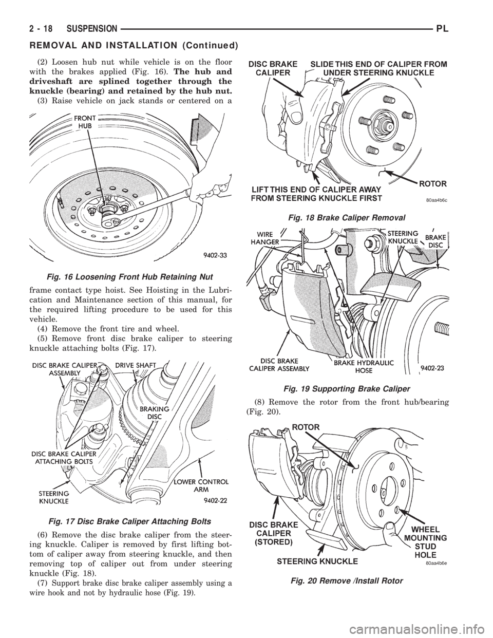
(2) Loosen hub nut while vehicle is on the floor
with the brakes applied (Fig. 16).The hub and
driveshaft are splined together through the
knuckle (bearing) and retained by the hub nut.
(3) Raise vehicle on jack stands or centered on a
frame contact type hoist. See Hoisting in the Lubri-
cation and Maintenance section of this manual, for
the required lifting procedure to be used for this
vehicle.
(4) Remove the front tire and wheel.
(5) Remove front disc brake caliper to steering
knuckle attaching bolts (Fig. 17).
(6) Remove the disc brake caliper from the steer-
ing knuckle. Caliper is removed by first lifting bot-
tom of caliper away from steering knuckle, and then
removing top of caliper out from under steering
knuckle (Fig. 18).
(7)
Support brake disc brake caliper assembly using a
wire hook and not by hydraulic hose (Fig. 19).
(8) Remove the rotor from the front hub/bearing
(Fig. 20).
Fig. 16 Loosening Front Hub Retaining Nut
Fig. 17 Disc Brake Caliper Attaching Bolts
Fig. 18 Brake Caliper Removal
Fig. 19 Supporting Brake Caliper
Fig. 20 Remove /Install Rotor
2 - 18 SUSPENSIONPL
REMOVAL AND INSTALLATION (Continued)
Page 32 of 1200
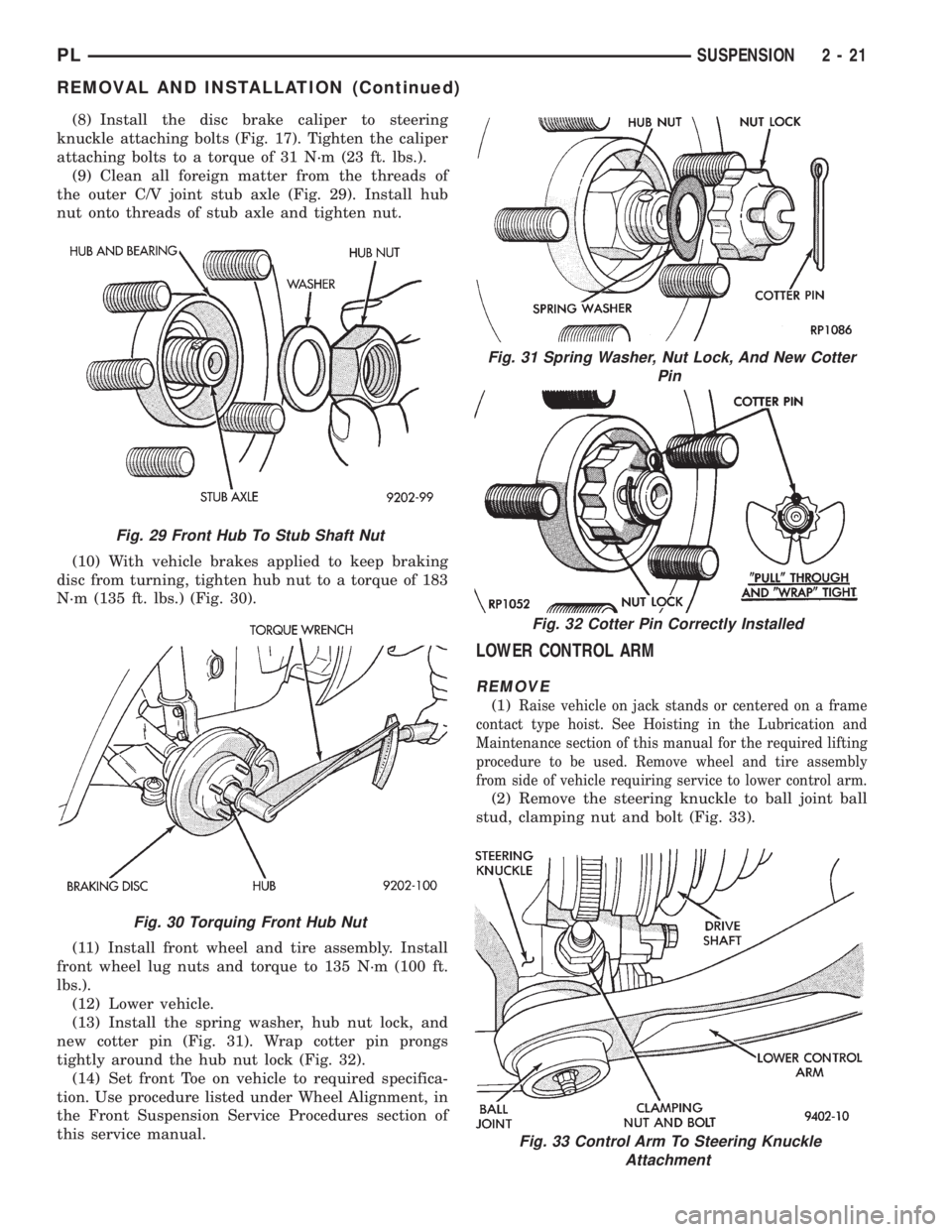
(8) Install the disc brake caliper to steering
knuckle attaching bolts (Fig. 17). Tighten the caliper
attaching bolts to a torque of 31 N´m (23 ft. lbs.).
(9) Clean all foreign matter from the threads of
the outer C/V joint stub axle (Fig. 29). Install hub
nut onto threads of stub axle and tighten nut.
(10) With vehicle brakes applied to keep braking
disc from turning, tighten hub nut to a torque of 183
N´m (135 ft. lbs.) (Fig. 30).
(11) Install front wheel and tire assembly. Install
front wheel lug nuts and torque to 135 N´m (100 ft.
lbs.).
(12) Lower vehicle.
(13) Install the spring washer, hub nut lock, and
new cotter pin (Fig. 31). Wrap cotter pin prongs
tightly around the hub nut lock (Fig. 32).
(14) Set front Toe on vehicle to required specifica-
tion. Use procedure listed under Wheel Alignment, in
the Front Suspension Service Procedures section of
this service manual.
LOWER CONTROL ARM
REMOVE
(1)Raise vehicle on jack stands or centered on a frame
contact type hoist. See Hoisting in the Lubrication and
Maintenance section of this manual for the required lifting
procedure to be used. Remove wheel and tire assembly
from side of vehicle requiring service to lower control arm.
(2) Remove the steering knuckle to ball joint ball
stud, clamping nut and bolt (Fig. 33).
Fig. 29 Front Hub To Stub Shaft Nut
Fig. 30 Torquing Front Hub Nut
Fig. 31 Spring Washer, Nut Lock, And New Cotter
Pin
Fig. 32 Cotter Pin Correctly Installed
Fig. 33 Control Arm To Steering Knuckle
Attachment
PLSUSPENSION 2 - 21
REMOVAL AND INSTALLATION (Continued)
Page 39 of 1200
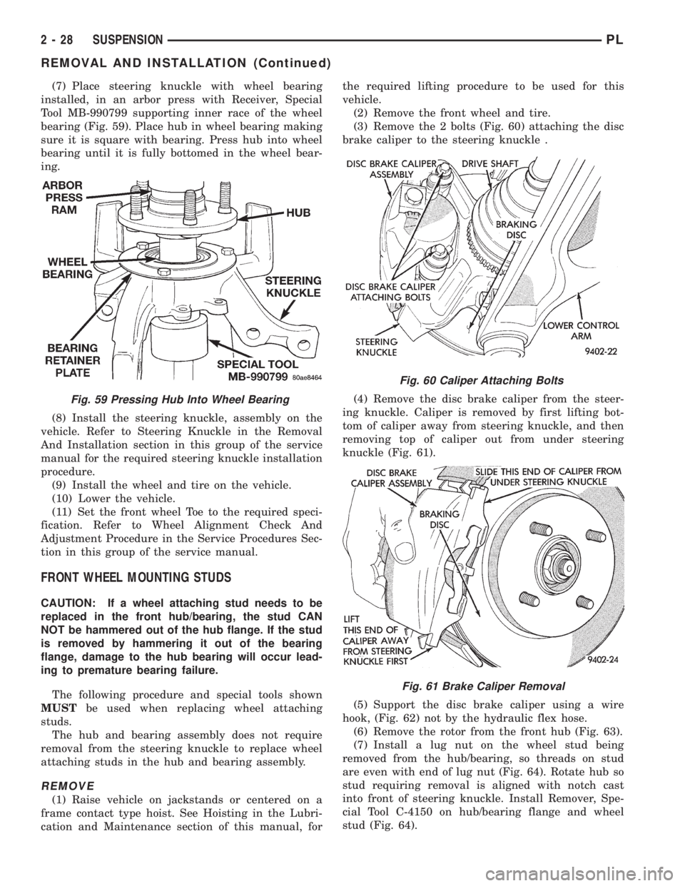
(7) Place steering knuckle with wheel bearing
installed, in an arbor press with Receiver, Special
Tool MB-990799 supporting inner race of the wheel
bearing (Fig. 59). Place hub in wheel bearing making
sure it is square with bearing. Press hub into wheel
bearing until it is fully bottomed in the wheel bear-
ing.
(8) Install the steering knuckle, assembly on the
vehicle. Refer to Steering Knuckle in the Removal
And Installation section in this group of the service
manual for the required steering knuckle installation
procedure.
(9) Install the wheel and tire on the vehicle.
(10) Lower the vehicle.
(11) Set the front wheel Toe to the required speci-
fication. Refer to Wheel Alignment Check And
Adjustment Procedure in the Service Procedures Sec-
tion in this group of the service manual.
FRONT WHEEL MOUNTING STUDS
CAUTION: If a wheel attaching stud needs to be
replaced in the front hub/bearing, the stud CAN
NOT be hammered out of the hub flange. If the stud
is removed by hammering it out of the bearing
flange, damage to the hub bearing will occur lead-
ing to premature bearing failure.
The following procedure and special tools shown
MUSTbe used when replacing wheel attaching
studs.
The hub and bearing assembly does not require
removal from the steering knuckle to replace wheel
attaching studs in the hub and bearing assembly.
REMOVE
(1) Raise vehicle on jackstands or centered on a
frame contact type hoist. See Hoisting in the Lubri-
cation and Maintenance section of this manual, forthe required lifting procedure to be used for this
vehicle.
(2) Remove the front wheel and tire.
(3) Remove the 2 bolts (Fig. 60) attaching the disc
brake caliper to the steering knuckle .
(4) Remove the disc brake caliper from the steer-
ing knuckle. Caliper is removed by first lifting bot-
tom of caliper away from steering knuckle, and then
removing top of caliper out from under steering
knuckle (Fig. 61).
(5) Support the disc brake caliper using a wire
hook, (Fig. 62) not by the hydraulic flex hose.
(6) Remove the rotor from the front hub (Fig. 63).
(7) Install a lug nut on the wheel stud being
removed from the hub/bearing, so threads on stud
are even with end of lug nut (Fig. 64). Rotate hub so
stud requiring removal is aligned with notch cast
into front of steering knuckle. Install Remover, Spe-
cial Tool C-4150 on hub/bearing flange and wheel
stud (Fig. 64).
Fig. 59 Pressing Hub Into Wheel Bearing
Fig. 60 Caliper Attaching Bolts
Fig. 61 Brake Caliper Removal
2 - 28 SUSPENSIONPL
REMOVAL AND INSTALLATION (Continued)