1999 DODGE NEON brake rotor
[x] Cancel search: brake rotorPage 9 of 1200
DISCONNECT CABLE CLAMPS AS FOLLOWS:
²Disconnect BLACK cable clamp from engine
ground on disabled vehicle.
²When using a Booster vehicle, disconnect
BLACK cable clamp from battery negative terminal.
Disconnect RED cable clamp from battery positive
terminal.
²Disconnect RED cable clamp from battery posi-
tive terminal on disabled vehicle.
TOWING RECOMMENDATIONS
WARNING: DO NOT ALLOW TOWING ATTACH-
MENT DEVICES TO CONTACT THE FUEL TANK OR
LINES, FUEL LEAK CAN RESULT. DO NOT LIFT OR
TOW VEHICLE BY FRONT OR REAR BUMPER, OR
BUMPER ENERGY ABSORBER UNITS. DO NOT
VENTURE UNDER A LIFTED VEHICLE IF NOT SUP-
PORTED PROPERLY ON SAFETY STANDS. DO NOT
ALLOW PASSENGERS TO RIDE IN A TOWED VEHI-
CLE. USE A SAFETY CHAIN THAT IS INDEPENDENT
FROM THE TOWING ATTACHMENT DEVICE.
CAUTION: Do not damage brake lines, exhaust
system, shock absorbers, sway bars, or any other
under vehicle components when attaching towing
device to vehicle. Do not attach towing device to
front or rear suspension components. Do not
secure vehicle to towing device by the use of front
or rear suspension or steering components.
Remove or secure loose or protruding objects from
a damaged vehicle before towing. Refer to state and
local rules and regulations before towing a vehicle.
Do not allow weight of towed vehicle to bear on
lower fascia, air dams, or spoilers.
RECOMMENDED TOWING EQUIPMENT
To avoid damage to bumper fascia and air dams
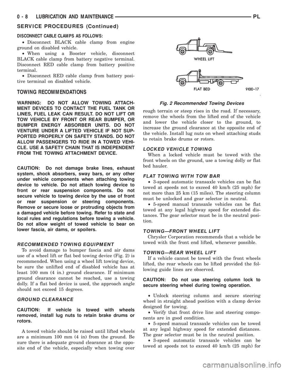
use of a wheel lift or flat bed towing device (Fig. 2) is
recommended. When using a wheel lift towing device,
be sure the unlifted end of disabled vehicle has at
least 100 mm (4 in.) ground clearance. If minimum
ground clearance cannot be reached, use a towing
dolly. If a flat bed device is used, the approach angle
should not exceed 15 degrees.
GROUND CLEARANCE
CAUTION: If vehicle is towed with wheels
removed, install lug nuts to retain brake drums or
rotors.
A towed vehicle should be raised until lifted wheels
are a minimum 100 mm (4 in) from the ground. Be
sure there is adequate ground clearance at the oppo-
site end of the vehicle, especially when towing overrough terrain or steep rises in the road. If necessary,
remove the wheels from the lifted end of the vehicle
and lower the vehicle closer to the ground, to
increase the ground clearance at the opposite end of
the vehicle. Install lug nuts on wheel attaching studs
to retain brake drums or rotors.
LOCKED VEHICLE TOWING
When a locked vehicle must be towed with the
front wheels on the ground, use a towing dolly or flat
bed hauler.
FLAT TOWING WITH TOW BAR
²3-speed automatic transaxle vehicles can be flat
towed at speeds not to exceed 40 km/h (25 mph) for
not more than 25 km (15 miles). The steering column
must be unlocked and gear selector in neutral.
²5-speed manual transaxle vehicles can be flat
towed at any legal highway speed for extended dis-
tances. The gear selector must be in the neutral posi-
tion.
TOWINGÐFRONT WHEEL LIFT
Chrysler Corporation recommends that a vehicle be
towed with the front end lifted, whenever possible.
TOWINGÐREAR WHEEL LIFT
If a vehicle cannot be towed with the front wheels
lifted, the rear wheels can be lifted provided the fol-
lowing guide lines are observed.
CAUTION: Do not use steering column lock to
secure steering wheel during towing operation.
²Unlock steering column and secure steering
wheel in straight ahead position with a clamp device
designed for towing.
²Verify that front drive line and steering compo-
nents are in good condition.
²5-speed manual transaxle vehicles can be towed
at any legal highway speed for extended distances.
The gear selector must be in the neutral position.
²3-speed automatic transaxle vehicles can be
towed at speeds not to exceed 40 km/h (25 mph) for
Fig. 2 Recommended Towing Devices
0 - 8 LUBRICATION AND MAINTENANCEPL
SERVICE PROCEDURES (Continued)
Page 27 of 1200

nent removal and installation sections in this group
of the service manual.
BALL JOINT ASSEMBLY
With the weight of the vehicle resting on the road
wheels. Grasp the grease fitting as shown in (Fig. 11)
and with no mechanical assistance or added force
attempt to move the grease fitting.
If the ball joint is worn the grease fitting will move
easily. If movement is noted, replacement of the ball
joint is recommended.
STABILIZER BAR
Inspect for broken or distorted sway bar bushings,
bushing retainers, and worn or damaged sway bar to
strut attaching links. If sway bar to front suspension
cradle bushing replacement is required, bushing can
be removed from sway bar by opening slit and peel-
ing bushing off sway bar.
HUB/BEARING
The hub bearing is designed for the life of the vehi-
cle and requires no type of periodic maintenance. The
following procedure may be used for diagnosing the
condition of the hub bearing.
With the wheel, disc brake caliper, and brake rotor
removed, rotate the wheel hub. Any roughness or
resistance to rotation may indicate dirt intrusion or a
failed hub bearing. If the hub bearing exhibits any of
these conditions during diagnosis, the hub bearing
will require replacement, the bearing is not service-
able.
Damaged bearing seals and the resulting excessive
grease loss may also require bearing replacement.
Moderate grease weapage from the hub bearing is
considered normal and should not require replace-
ment of the hub bearing.
REMOVAL AND INSTALLATION
MCPHERSON STRUT
REMOVE
WARNING: DO NOT REMOVE STRUT ROD NUT
WHILE STRUT ASSEMBLY IS INSTALLED IN VEHI-
CLE, OR BEFORE STRUT ASSEMBLY SPRING IS
COMPRESSED.
(1) Loosen wheel nuts.
(2) Raise vehicle on jack stands or centered on a
frame contact type hoist. See Hoisting in the Lubri-
cation and Maintenance section of this manual, for
the required lifting procedure to be used for this
vehicle.
(3) Remove wheel and tire assembly from location
on front of vehicle requiring strut removal.
(4) If both strut assemblies are removed, mark the
strut assemblies right or left according to which side
of the vehicle they were removed from.
(5) Remove hydraulic brake hose routing bracket
and attaching screw from strut damper bracket. If
vehicle is equipped with Anti-Lock brakes, hydraulic
hose routing bracket is combined with speed sensor
cable routing bracket (Fig. 12).
CAUTION: The steering knuckle to strut assembly
attaching bolts are serrated and must not be turned
during removal. Remove nuts while holding bolts
stationary in the steering knuckles.
(6) Remove the 2 bolts (Fig. 13) attaching the strut
to the steering knuckle.
(7) Remove the 3 nuts attaching the upper mount
of the strut (Fig. 14) to the strut tower of the vehicle
.
INSTALL
(1) Install strut assembly into strut tower, aligning
the 3 studs on the upper strut mount into the holes
in shock tower. Install the 3 upper strut mount
retaining nut and washer assemblies (Fig. 14).
Torque the 3 nuts to 31 N´m (23 ft. lbs.).
CAUTION: The steering knuckle to strut assembly
attaching bolts are serrated and must not be turned
during installation. Install nuts while holding bolts
stationary in the steering knuckles.
(2) Align strut assembly with steering knuckle.
Position arm of steering knuckle into strut assembly,
aligning the strut assembly to steering knuckle
mounting holes. Install the 2 strut assembly to steer-
ing knuckle attaching bolts (Fig. 13). Attaching bolts
should be installed with the nuts facing the front of
the vehicle. Torque both attaching bolts to 53 N´m
Fig. 11 Checking Ball Joint Wear
2 - 16 SUSPENSIONPL
DIAGNOSIS AND TESTING (Continued)
Page 29 of 1200
(2) Loosen hub nut while vehicle is on the floor
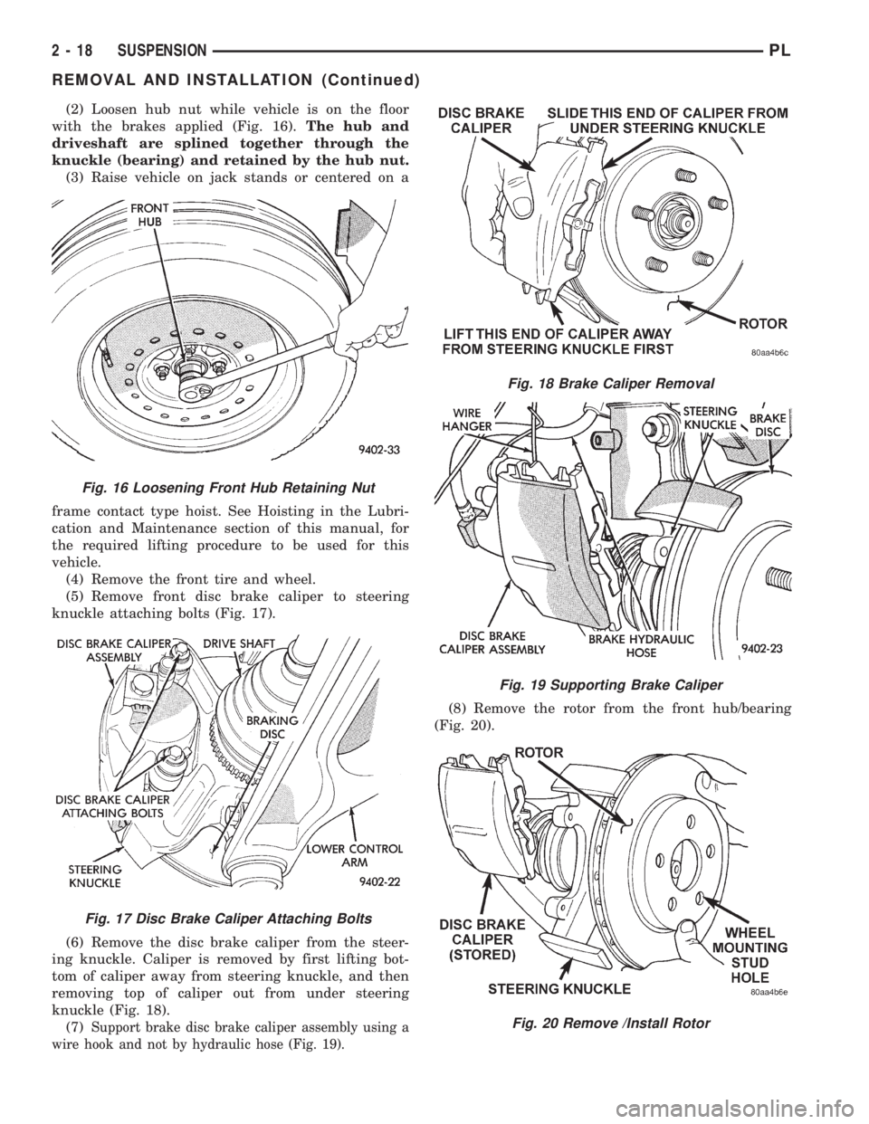
with the brakes applied (Fig. 16).The hub and
driveshaft are splined together through the
knuckle (bearing) and retained by the hub nut.
(3) Raise vehicle on jack stands or centered on a
frame contact type hoist. See Hoisting in the Lubri-
cation and Maintenance section of this manual, for
the required lifting procedure to be used for this
vehicle.
(4) Remove the front tire and wheel.
(5) Remove front disc brake caliper to steering
knuckle attaching bolts (Fig. 17).
(6) Remove the disc brake caliper from the steer-
ing knuckle. Caliper is removed by first lifting bot-
tom of caliper away from steering knuckle, and then
removing top of caliper out from under steering
knuckle (Fig. 18).
(7)
Support brake disc brake caliper assembly using a
wire hook and not by hydraulic hose (Fig. 19).
(8) Remove the rotor from the front hub/bearing
(Fig. 20).
Fig. 16 Loosening Front Hub Retaining Nut
Fig. 17 Disc Brake Caliper Attaching Bolts
Fig. 18 Brake Caliper Removal
Fig. 19 Supporting Brake Caliper
Fig. 20 Remove /Install Rotor
2 - 18 SUSPENSIONPL
REMOVAL AND INSTALLATION (Continued)
Page 31 of 1200
CAUTION: The steering knuckle to strut assembly
attaching bolts are serrated and must not be turned
during removal. Remove nuts while holding bolts
stationary in the steering knuckles.
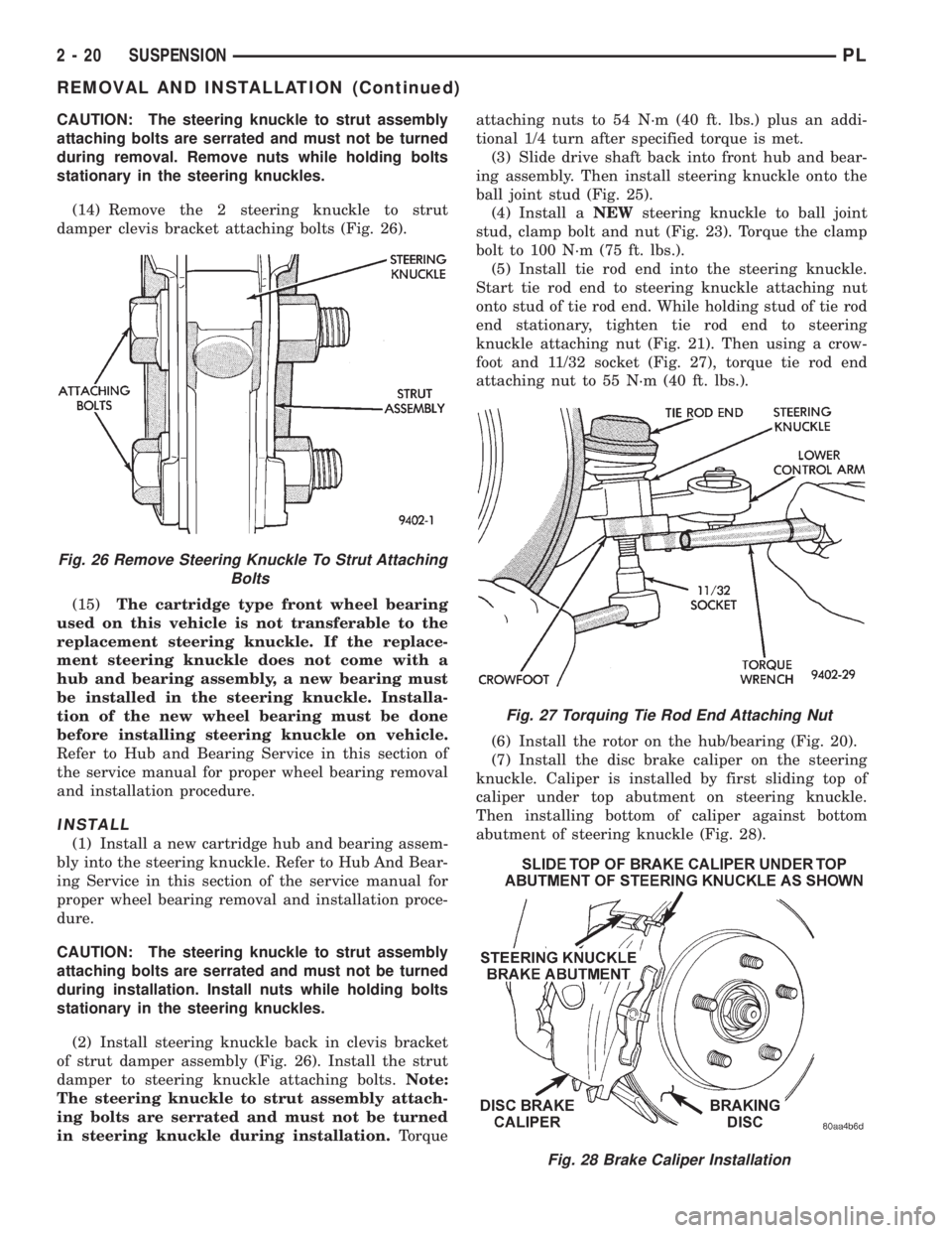
(14) Remove the 2 steering knuckle to strut
damper clevis bracket attaching bolts (Fig. 26).
(15)The cartridge type front wheel bearing
used on this vehicle is not transferable to the
replacement steering knuckle. If the replace-
ment steering knuckle does not come with a
hub and bearing assembly, a new bearing must
be installed in the steering knuckle. Installa-
tion of the new wheel bearing must be done
before installing steering knuckle on vehicle.
Refer to Hub and Bearing Service in this section of
the service manual for proper wheel bearing removal
and installation procedure.
INSTALL
(1) Install a new cartridge hub and bearing assem-
bly into the steering knuckle. Refer to Hub And Bear-
ing Service in this section of the service manual for
proper wheel bearing removal and installation proce-
dure.
CAUTION: The steering knuckle to strut assembly
attaching bolts are serrated and must not be turned
during installation. Install nuts while holding bolts
stationary in the steering knuckles.
(2) Install steering knuckle back in clevis bracket
of strut damper assembly (Fig. 26). Install the strut
damper to steering knuckle attaching bolts.Note:
The steering knuckle to strut assembly attach-
ing bolts are serrated and must not be turned
in steering knuckle during installation.Torqueattaching nuts to 54 N´m (40 ft. lbs.) plus an addi-
tional 1/4 turn after specified torque is met.
(3) Slide drive shaft back into front hub and bear-
ing assembly. Then install steering knuckle onto the
ball joint stud (Fig. 25).
(4) Install aNEWsteering knuckle to ball joint
stud, clamp bolt and nut (Fig. 23). Torque the clamp
bolt to 100 N´m (75 ft. lbs.).
(5) Install tie rod end into the steering knuckle.
Start tie rod end to steering knuckle attaching nut
onto stud of tie rod end. While holding stud of tie rod
end stationary, tighten tie rod end to steering
knuckle attaching nut (Fig. 21). Then using a crow-
foot and 11/32 socket (Fig. 27), torque tie rod end
attaching nut to 55 N´m (40 ft. lbs.).
(6) Install the rotor on the hub/bearing (Fig. 20).
(7) Install the disc brake caliper on the steering
knuckle. Caliper is installed by first sliding top of
caliper under top abutment on steering knuckle.
Then installing bottom of caliper against bottom
abutment of steering knuckle (Fig. 28).
Fig. 28 Brake Caliper Installation
Fig. 26 Remove Steering Knuckle To Strut Attaching
Bolts
Fig. 27 Torquing Tie Rod End Attaching Nut
2 - 20 SUSPENSIONPL
REMOVAL AND INSTALLATION (Continued)
Page 39 of 1200
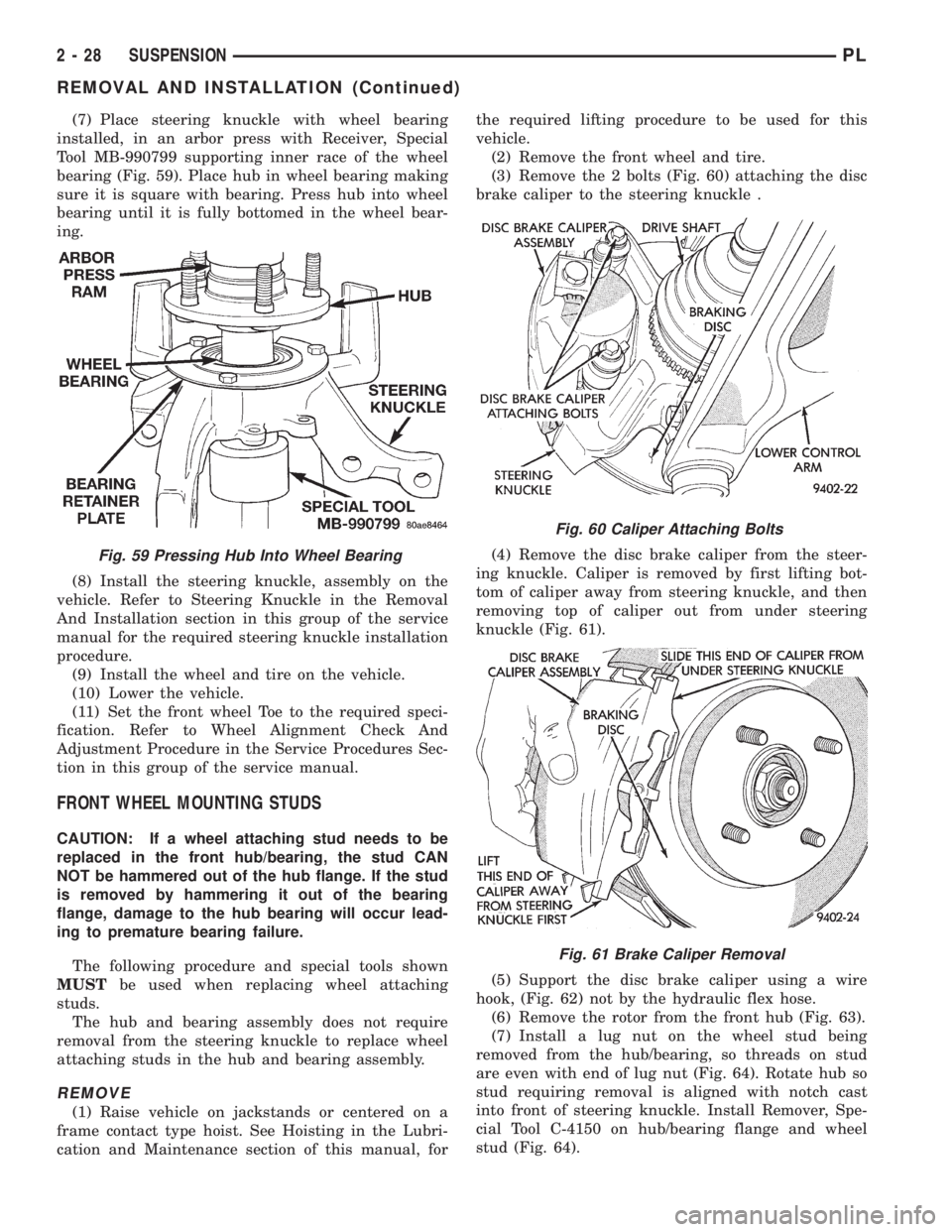
(7) Place steering knuckle with wheel bearing
installed, in an arbor press with Receiver, Special
Tool MB-990799 supporting inner race of the wheel
bearing (Fig. 59). Place hub in wheel bearing making
sure it is square with bearing. Press hub into wheel
bearing until it is fully bottomed in the wheel bear-
ing.
(8) Install the steering knuckle, assembly on the
vehicle. Refer to Steering Knuckle in the Removal
And Installation section in this group of the service
manual for the required steering knuckle installation
procedure.
(9) Install the wheel and tire on the vehicle.
(10) Lower the vehicle.
(11) Set the front wheel Toe to the required speci-
fication. Refer to Wheel Alignment Check And
Adjustment Procedure in the Service Procedures Sec-
tion in this group of the service manual.
FRONT WHEEL MOUNTING STUDS
CAUTION: If a wheel attaching stud needs to be
replaced in the front hub/bearing, the stud CAN
NOT be hammered out of the hub flange. If the stud
is removed by hammering it out of the bearing
flange, damage to the hub bearing will occur lead-
ing to premature bearing failure.
The following procedure and special tools shown
MUSTbe used when replacing wheel attaching
studs.
The hub and bearing assembly does not require
removal from the steering knuckle to replace wheel
attaching studs in the hub and bearing assembly.
REMOVE
(1) Raise vehicle on jackstands or centered on a
frame contact type hoist. See Hoisting in the Lubri-
cation and Maintenance section of this manual, forthe required lifting procedure to be used for this
vehicle.
(2) Remove the front wheel and tire.
(3) Remove the 2 bolts (Fig. 60) attaching the disc
brake caliper to the steering knuckle .
(4) Remove the disc brake caliper from the steer-
ing knuckle. Caliper is removed by first lifting bot-
tom of caliper away from steering knuckle, and then
removing top of caliper out from under steering
knuckle (Fig. 61).
(5) Support the disc brake caliper using a wire
hook, (Fig. 62) not by the hydraulic flex hose.
(6) Remove the rotor from the front hub (Fig. 63).
(7) Install a lug nut on the wheel stud being
removed from the hub/bearing, so threads on stud
are even with end of lug nut (Fig. 64). Rotate hub so
stud requiring removal is aligned with notch cast
into front of steering knuckle. Install Remover, Spe-
cial Tool C-4150 on hub/bearing flange and wheel
stud (Fig. 64).
Fig. 59 Pressing Hub Into Wheel Bearing
Fig. 60 Caliper Attaching Bolts
Fig. 61 Brake Caliper Removal
2 - 28 SUSPENSIONPL
REMOVAL AND INSTALLATION (Continued)
Page 40 of 1200
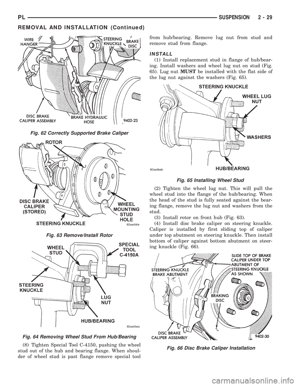
(8) Tighten Special Tool C-4150, pushing the wheel
stud out of the hub and bearing flange. When shoul-
der of wheel stud is past flange remove special toolfrom hub/bearing. Remove lug nut from stud and
remove stud from flange.
INSTALL
(1) Install replacement stud in flange of hub/bear-
ing. Install washers and wheel lug nut on stud (Fig.
65). Lug nutMUSTbe installed with the flat side of
the lug nut against the washers (Fig. 65).
(2) Tighten the wheel lug nut. This will pull the
wheel stud into the flange of the hub/bearing. When
the head of the stud is fully seated against the bear-
ing flange, remove the lug nut and washers from the
stud.
(3) Install rotor on front hub (Fig. 63).
(4) Install disc brake caliper on steering knuckle.
Caliper is installed by first sliding top of caliper
under top abutment on steering knuckle. Then install
bottom of caliper against bottom abutment on steer-
ing knuckle (Fig. 66).
Fig. 62 Correctly Supported Brake Caliper
Fig. 63 Remove/Install Rotor
Fig. 64 Removing Wheel Stud From Hub/Bearing
Fig. 65 Installing Wheel Stud
Fig. 66 Disc Brake Caliper Installation
PLSUSPENSION 2 - 29
REMOVAL AND INSTALLATION (Continued)
Page 57 of 1200

sequence until all nuts are torqued to half specifica-
tion. Then repeat the tightening sequence to the full
specified torque of 129 N´m (95 ft. lbs.).
(5) Lower the vehicle to the ground.
(6) With suspension supporting the full weight of
the vehicle, securely tighten the stabilizer bar
retainer to frame rail attaching bolts (Fig. 11).
KNUCKLE
REMOVE
(1) Raise vehicle on jackstands or centered on a
frame contact type hoist. See Hoisting in the Lubri-
cation and Maintenance section of this manual, for
the required lifting procedure to be used for this
vehicle.
(2) Remove the rear wheel and tire.
(3) If vehicle is equipped with rear disc brakes,
remove the rear caliper from the adapter. Refer to
Rear Disk Brakes in Group 5 Brakes of this Service
manual for required caliper removal procedure. After
removing the caliper, store the caliper by hanging it
from frame of the vehicle (Fig. 14). Do not let weight
of rear caliper hang from flexible brake hose.
(4) If vehicle is equipped with rear disc brakes,
remove rotor from hub. If vehicle is equipped with
rear drum brakes, remove brake drum from hub.
(5) If vehicle is equipped with ABS brakes, remove
wheel speed sensor from rear disc brake adapter
(Fig. 15).
(6) Remove rear hub/bearing retaining nut (Fig.
16). Then remove the hub/bearing from the knuckle.(7) If vehicle is equipped with rear drum brakes
remove the 4 bolts (Fig. 17) attaching rear brake sup-
port plate to knuckle. Then remove brake support
plate, brake shoes and wheel cylinder as an assembly
from rear knuckle (Fig. 17).It is not necessary to
remove brake flex hose from wheel cylinder
when removing support plate.Brake support
plate when removed, must be supported in same
manner as caliper assembly.
(8) On vehicles equipped with rear disc brakes,
remove the 4 bolts attaching disc brake adapter to
rear knuckle (Fig. 18). Then remove the adapter,
rotor shield, park brake shoes and park brake cable
as an assembly from knuckle.
CAUTION: The knuckle to strut assembly attaching
bolts are serrated and must not be turned during
removal. Loosen and remove nuts while holding
bolts stationary in knuckle.
Fig. 14 Storing Rear Caliper
Fig. 15 Speed Sensor Head Attachment To Disc
Brake Adapter
Fig. 16 Hub/ Bearing Retaining Nut
2 - 46 SUSPENSIONPL
REMOVAL AND INSTALLATION (Continued)
Page 83 of 1200
BASE BRAKE SYSTEM
INDEX
page page
DESCRIPTION AND OPERATION
CHASSIS TUBES AND HOSES.............. 6
FRONT DISC BRAKES..................... 2
MASTER CYLINDER...................... 6
PARKING BRAKES........................ 4
PROPORTIONING VALVES................. 5
REAR DISC BRAKES...................... 4
REAR DRUM BRAKES..................... 4
REAR WHEEL HUB/BEARING............... 8
RED BRAKE WARNING LAMP............... 7
STOP LAMP SWITCH...................... 8
VACUUM BOOSTER...................... 6
DIAGNOSIS AND TESTING
BRAKE FLUID CONTAMINATION............ 19
BRAKE SYSTEM BASIC DIAGNOSIS GUIDE.... 9
BRAKE SYSTEM DIAGNOSIS CHARTS....... 10
DRUM BRAKE AUTOMATIC ADJUSTER....... 14
PROPORTIONING VALVES................ 16
RED BRAKE WARNING LAMP TEST......... 19
ROTOR THICKNESS AND RUNOUT.......... 14
STOP LAMP SWITCH TEST PROCEDURE..... 19
SERVICE PROCEDURES
BRAKE BLEEDING....................... 20
BRAKE DRUM MACHINING................ 23
BRAKE FLUID LEVEL CHECK.............. 19
BRAKE ROTOR MACHINING............... 22
BRAKE TUBE REPAIR.................... 25
MASTER CYLINDER BLEEDING............ 21
PARK BRAKE LEVER AUTO ADJUSTER
MECHANISM.......................... 23
REMOVAL AND INSTALLATION
CHASSIS TUBES AND HOSES.............. 47
FRONT DISC BRAKE CALIPER............. 26
FRONT DISC BRAKE SHOES.............. 28
MASTER CYLINDER..................... 41
PARK BRAKE CABLES.................... 50
PARK BRAKE LEVER ASSEMBLY........... 48PARK BRAKE LEVER OUTPUT CABLE....... 49
PARK BRAKE SHOES WITH REAR DISC
BRAKES............................. 55
PROPORTIONING VALVE (BASE BRAKES).... 47
REAR BRAKE DRUM..................... 34
REAR BRAKE SHOE SUPPORT PLATE....... 37
REAR BRAKE SHOES.................... 35
REAR BRAKE WHEEL CYLINDER........... 38
REAR DISC BRAKE CALIPER.............. 30
REAR DISC BRAKE SHOES................ 32
REAR HUB/BEARING..................... 39
STOP LAMP SWITCH..................... 57
VACUUM BOOSTER..................... 44
WHEEL AND TIRE ASSEMBLY.............. 26
DISASSEMBLY AND ASSEMBLY
BRAKE FLUID LEVEL SWITCH............. 58
BRAKE FLUID RESERVOIR................ 57
FRONT AND REAR DISC BRAKE CALIPER.... 58
WHEEL CYLINDER (REAR DRUM BRAKE).... 63
CLEANING AND INSPECTION
CHASSIS TUBES AND HOSES.............. 65
FRONT DISC BRAKES.................... 63
REAR DISC BRAKES..................... 64
REAR DRUM BRAKE WHEEL CYLINDER...... 65
REAR DRUM BRAKES.................... 64
REAR WHEEL HUB AND BEARING ASSEMBLY . 65
ADJUSTMENTS
PARK BRAKE ADJUSTMENT............... 66
REAR DRUM BRAKE SHOE ADJUSTMENT.... 65
STOP LAMP SWITCH..................... 65
SPECIFICATIONS
BRAKE ACTUATION SYSTEM.............. 67
BRAKE FASTENER TORQUE SPECIFICATIONS . 67
BRAKE FLUID.......................... 67
SPECIAL TOOLS
BASE BRAKE SYSTEM................... 68
DESCRIPTION AND OPERATION
FRONT DISC BRAKES
The front disc brakes (Fig. 1) and (Fig. 2) consists
of the following components:
²The driving hub
²Braking disc (rotor)
²Caliper assembly - single piston, floating type
²Brake shoes and linings
The double pin calipers are mounted directly to the
steering knuckles and use no adapter. The caliper ismounted to the steering knuckle using bushings,
sleeves and 2 guide pin bolts which thread directly
into bosses on the steering knuckle (Fig. 2) and (Fig.
3).
Two machined abutments on the steering knuckle
position the caliper. The guide pin bolts, sleeves and
bushings control the side to side movement of the
caliper. The piston seal is designed to pull the piston
back into the bore of the caliper when the brake
pedal is released. This maintains the proper brake
shoe to rotor clearance (Fig. 4).
5 - 2 BRAKESPL