1999 DODGE NEON bolt pattern
[x] Cancel search: bolt patternPage 121 of 1200
INSTALL
CAUTION: The hub/bearing retaining nut must be
tightened to but must not exceed its required
torque specification. The proper torque specifica-
tion of the retaining nut is critical to the life of the
hub bearing.
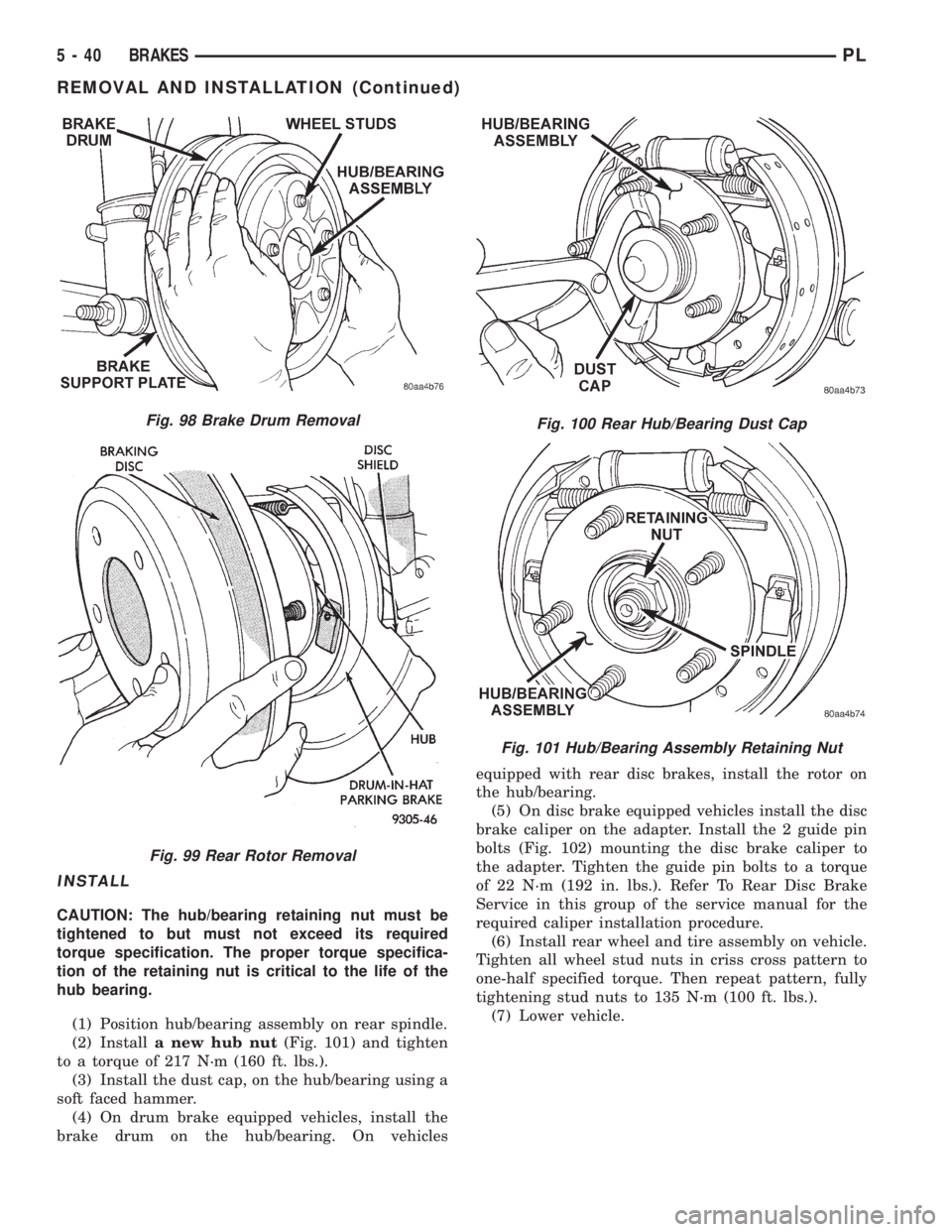
(1) Position hub/bearing assembly on rear spindle.
(2) Installa new hub nut(Fig. 101) and tighten
to a torque of 217 N´m (160 ft. lbs.).
(3) Install the dust cap, on the hub/bearing using a
soft faced hammer.
(4) On drum brake equipped vehicles, install the
brake drum on the hub/bearing. On vehiclesequipped with rear disc brakes, install the rotor on
the hub/bearing.
(5) On disc brake equipped vehicles install the disc
brake caliper on the adapter. Install the 2 guide pin
bolts (Fig. 102) mounting the disc brake caliper to
the adapter. Tighten the guide pin bolts to a torque
of 22 N´m (192 in. lbs.). Refer To Rear Disc Brake
Service in this group of the service manual for the
required caliper installation procedure.
(6) Install rear wheel and tire assembly on vehicle.
Tighten all wheel stud nuts in criss cross pattern to
one-half specified torque. Then repeat pattern, fully
tightening stud nuts to 135 N´m (100 ft. lbs.).
(7) Lower vehicle.
Fig. 98 Brake Drum Removal
Fig. 99 Rear Rotor Removal
Fig. 100 Rear Hub/Bearing Dust Cap
Fig. 101 Hub/Bearing Assembly Retaining Nut
5 - 40 BRAKESPL
REMOVAL AND INSTALLATION (Continued)
Page 135 of 1200
INSTALL
(1) Install park brake cable into floor pan of vehi-
cle making sure sealing grommet is installed in floor
pan as far as possible to insure proper seal.
(2) Install park brake cable into brake support
plate or rear disc brake adapter. Be sure locking tabs
on cable retainer are expanded to ensure park brake
cable is securely held in support plate or adapter.
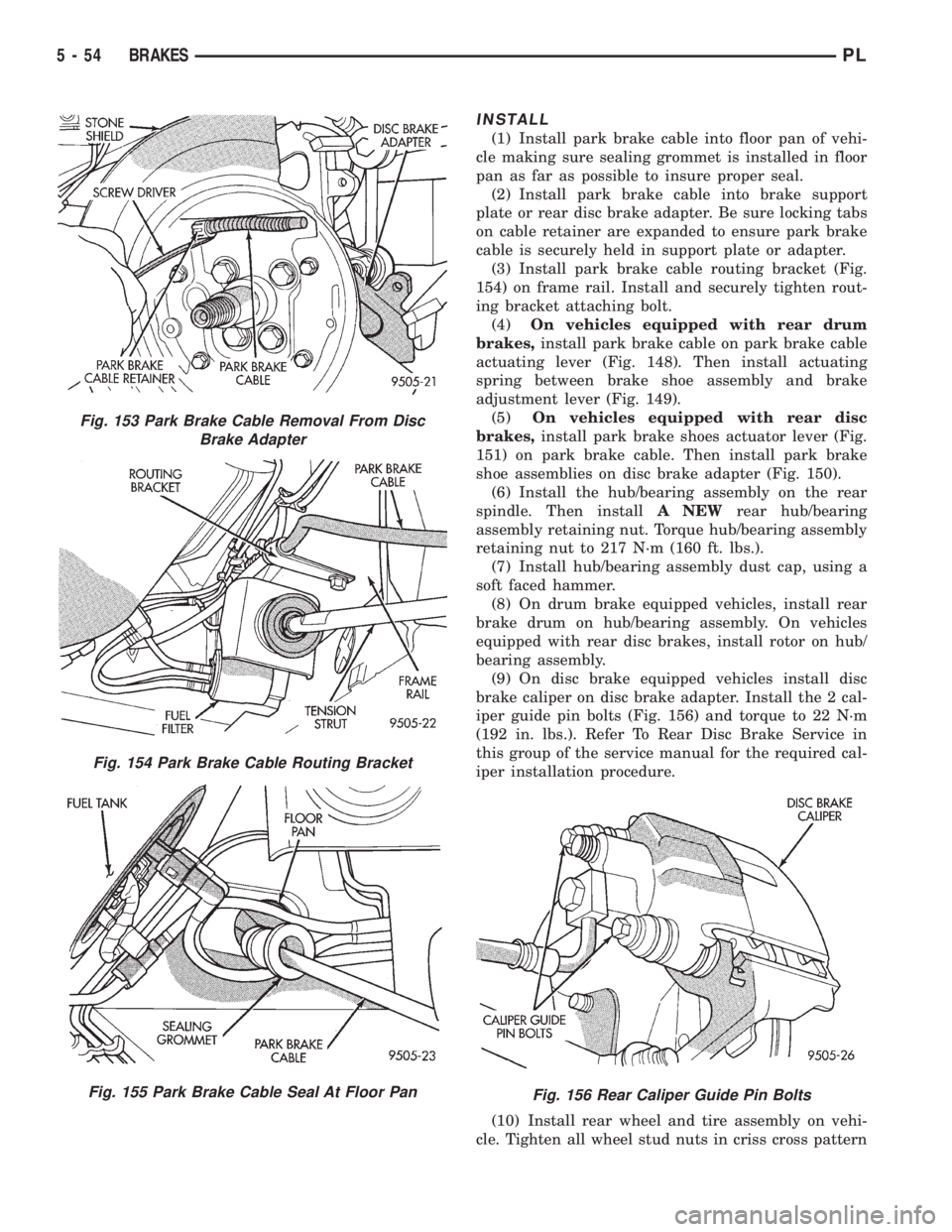
(3) Install park brake cable routing bracket (Fig.
154) on frame rail. Install and securely tighten rout-
ing bracket attaching bolt.
(4)On vehicles equipped with rear drum
brakes,install park brake cable on park brake cable
actuating lever (Fig. 148). Then install actuating
spring between brake shoe assembly and brake
adjustment lever (Fig. 149).
(5)On vehicles equipped with rear disc
brakes,install park brake shoes actuator lever (Fig.
151) on park brake cable. Then install park brake
shoe assemblies on disc brake adapter (Fig. 150).
(6) Install the hub/bearing assembly on the rear
spindle. Then installA NEWrear hub/bearing
assembly retaining nut. Torque hub/bearing assembly
retaining nut to 217 N´m (160 ft. lbs.).
(7) Install hub/bearing assembly dust cap, using a
soft faced hammer.
(8) On drum brake equipped vehicles, install rear
brake drum on hub/bearing assembly. On vehicles
equipped with rear disc brakes, install rotor on hub/
bearing assembly.
(9) On disc brake equipped vehicles install disc
brake caliper on disc brake adapter. Install the 2 cal-
iper guide pin bolts (Fig. 156) and torque to 22 N´m
(192 in. lbs.). Refer To Rear Disc Brake Service in
this group of the service manual for the required cal-
iper installation procedure.
(10) Install rear wheel and tire assembly on vehi-
cle. Tighten all wheel stud nuts in criss cross pattern
Fig. 153 Park Brake Cable Removal From Disc
Brake Adapter
Fig. 154 Park Brake Cable Routing Bracket
Fig. 155 Park Brake Cable Seal At Floor PanFig. 156 Rear Caliper Guide Pin Bolts
5 - 54 BRAKESPL
Page 179 of 1200
REMOVAL
(1) Remove transaxle. See Group 21, Manual Tran-
saxle, for procedure.
(2) Mark clutch cover and flywheel, to maintain
their same relative positions when installing clutch
assembly.
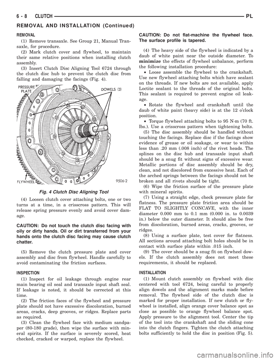
(3) Insert Clutch Disc Aligning Tool 6724 through
the clutch disc hub to prevent the clutch disc from
falling and damaging the facings (Fig. 4).
(4) Loosen clutch cover attaching bolts, one or two
turns at a time, in a crisscross pattern. This will
release spring pressure evenly and avoid cover dam-
age.
CAUTION: Do not touch the clutch disc facing with
oily or dirty hands. Oil or dirt transferred from your
hands onto the clutch disc facing may cause clutch
chatter.
(5) Remove the clutch pressure plate and cover
assembly and disc from flywheel. Handle carefully to
avoid contaminating the friction surfaces.
INSPECTION
(1) Inspect for oil leakage through engine rear
main bearing oil seal and transaxle input shaft seal.
If leakage is noted, it should be corrected at this
time.
(2) The friction faces of the flywheel and pressure
plate should not have excessive discoloration, burned
areas, cracks, deep grooves, or ridges. Replace parts
as required.
(3) Clean the flywheel face with medium sandpa-
per (80-180 grade), then wipe the surface with min-
eral spirits. If the surface is severely scored, heat
checked, cracked or warped, replace the flywheel.CAUTION: Do not flat-machine the flywheel face.
The surface profile is tapered.
(4) The heavy side of the flywheel is indicated by a
daub of white paint near the outside diameter. To
minimizethe effects of flywheel unbalance, perform
the following installation procedure:
²Loose assemble the flywheel to the crankshaft.
Use new flywheel attaching bolts which have sealant
on the threads. If new bolts are not available, apply
Loctite sealant to the threads of the original bolts.
This sealant is required to prevent engine oil leak-
age.
²Rotate the flywheel and crankshaft until the
daub of white paint (heavy side) is at the 12 o'clock
position.
²Torque flywheel attaching bolts to 95 N´m (70 ft.
lbs.). Use a crisscross pattern when tightening bolts.
(5) The disc assembly should be handled without
touching the facings. Replace disc if the facings show
evidence of grease or oil soakage, or wear to within
less than .20 mm (.008 inch) of the rivet heads. The
splines on the disc hub and transaxle input shaft
should be a snug fit without signs of excessive wear.
Metallic portions of disc assembly should be dry,
clean, and not discolored from excessive heat. Each of
the arched springs between the facings should not be
broken and all rivets should be tight.
(6) Wipe the friction surface of the pressure plate
with mineral spirits.
(7) Using a straight edge, check pressure plate for
flatness. The pressure plate friction area should be
FLAT TO SLIGHTLY CONCAVE, with the inner
diameter 0.000 mm to 0.1 mm (0.000 in. to 0.0039
in.) below the outer diameter. It should also be free
from discoloration, burned areas, cracks, grooves, or
ridges.
(8) Using a surface plate, test cover for flatness.
All sections around attaching bolt holes should be in
contact with surface plate within .015 inch.
(9) The cover should be a snug fit on flywheel dow-
els. If the clutch assembly does not meet these
requirements, it should be replaced.
INSTALLATION
(1) Mount clutch assembly on flywheel with disc
centered with tool 6724, being careful to properly
align dowels and the alignment marks made before
removal. The flywheel side of the clutch disc is
marked for proper installation. If new clutch or fly-
wheel is installed, align orange cover balance spot as
close as possible to orange flywheel balance spot.
Apply pressure to the alignment tool. Center the tip
of the tool into the crankshaft and the sliding cone
into the clutch fingers. Tighten the clutch attaching
bolts sufficiently to hold the disc in position (Fig. 5).
Fig. 4 Clutch Disc Aligning Tool
6 - 8 CLUTCHPL
REMOVAL AND INSTALLATION (Continued)
Page 180 of 1200
(2) To avoid distortion of the clutch cover, bolts
should be tightened a few turns at a time. Use a
crisscross pattern, until all bolts are seated. Tighten
bolts to 28 N´m (250 in. lbs.) following a crisscross
pattern sequence. Remove clutch disc alignment tool.
(3) Install transaxle. See Group 21, Manual Tran-
saxle for procedures.
BELVIDERE BUILT VEHICLES
The transaxle must be removed to service the mod-
ular clutch disc assembly and lever.
REMOVAL
(1) Remove the starter wiring. Remove the starter
assembly.
(2) Remove the rear transaxle support bracket.
(3) Remove the front transaxle support bracket.
(4) Remove modular clutch retaining bolts.
(5) Remove transaxle. See Group 21, Manual Tran-
saxle, for procedure.
(6) The transaxle and modular clutch come out as
an assembly.
(7) Remove the modular clutch assembly from the
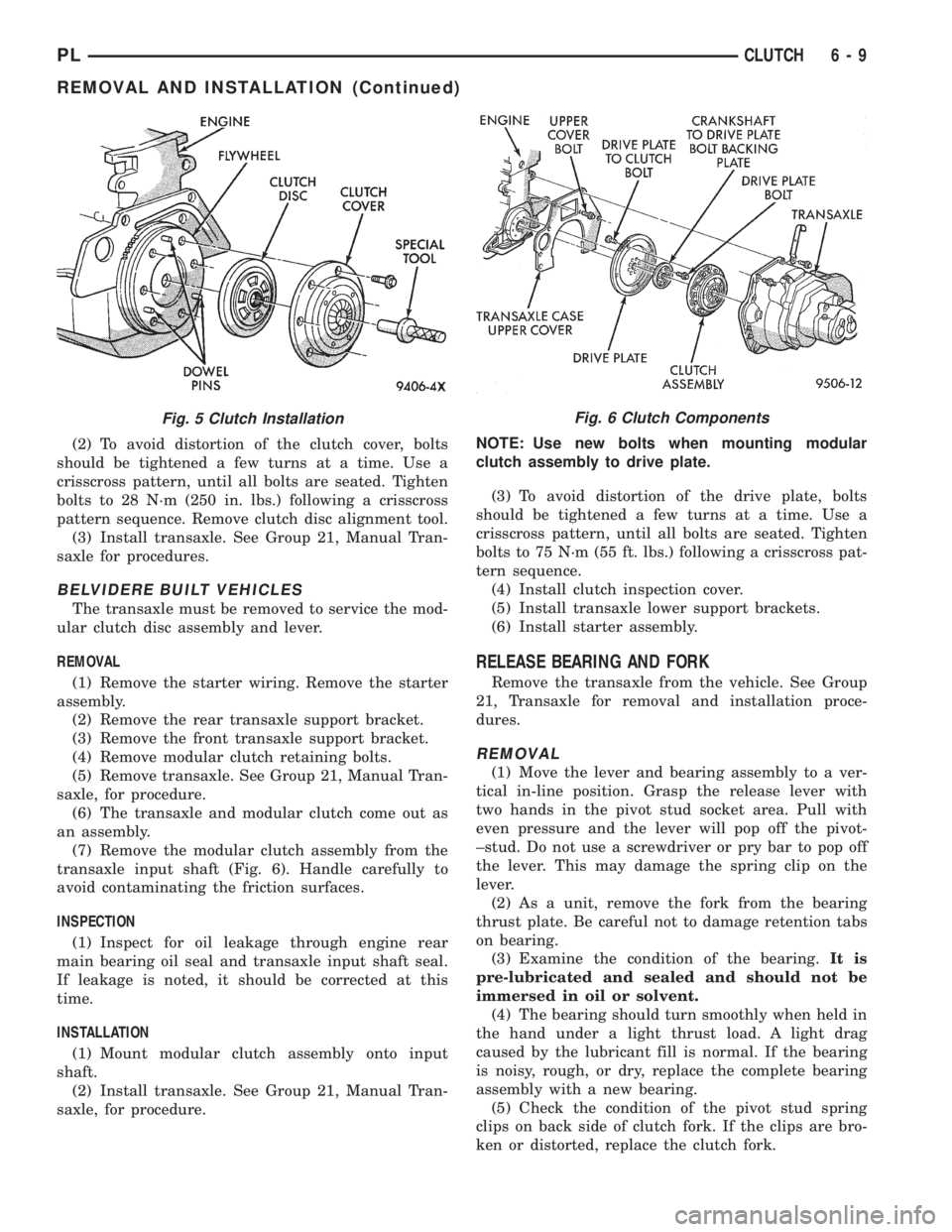
transaxle input shaft (Fig. 6). Handle carefully to
avoid contaminating the friction surfaces.
INSPECTION
(1) Inspect for oil leakage through engine rear
main bearing oil seal and transaxle input shaft seal.
If leakage is noted, it should be corrected at this
time.
INSTALLATION
(1) Mount modular clutch assembly onto input
shaft.
(2) Install transaxle. See Group 21, Manual Tran-
saxle, for procedure.NOTE: Use new bolts when mounting modular
clutch assembly to drive plate.
(3) To avoid distortion of the drive plate, bolts
should be tightened a few turns at a time. Use a
crisscross pattern, until all bolts are seated. Tighten
bolts to 75 N´m (55 ft. lbs.) following a crisscross pat-
tern sequence.
(4) Install clutch inspection cover.
(5) Install transaxle lower support brackets.
(6) Install starter assembly.
RELEASE BEARING AND FORK
Remove the transaxle from the vehicle. See Group
21, Transaxle for removal and installation proce-
dures.
REMOVAL
(1) Move the lever and bearing assembly to a ver-
tical in-line position. Grasp the release lever with
two hands in the pivot stud socket area. Pull with
even pressure and the lever will pop off the pivot-
±stud. Do not use a screwdriver or pry bar to pop off
the lever. This may damage the spring clip on the
lever.
(2) As a unit, remove the fork from the bearing
thrust plate. Be careful not to damage retention tabs
on bearing.
(3) Examine the condition of the bearing.It is
pre-lubricated and sealed and should not be
immersed in oil or solvent.
(4) The bearing should turn smoothly when held in
the hand under a light thrust load. A light drag
caused by the lubricant fill is normal. If the bearing
is noisy, rough, or dry, replace the complete bearing
assembly with a new bearing.
(5) Check the condition of the pivot stud spring
clips on back side of clutch fork. If the clips are bro-
ken or distorted, replace the clutch fork.
Fig. 6 Clutch ComponentsFig. 5 Clutch Installation
PLCLUTCH 6 - 9
REMOVAL AND INSTALLATION (Continued)
Page 192 of 1200
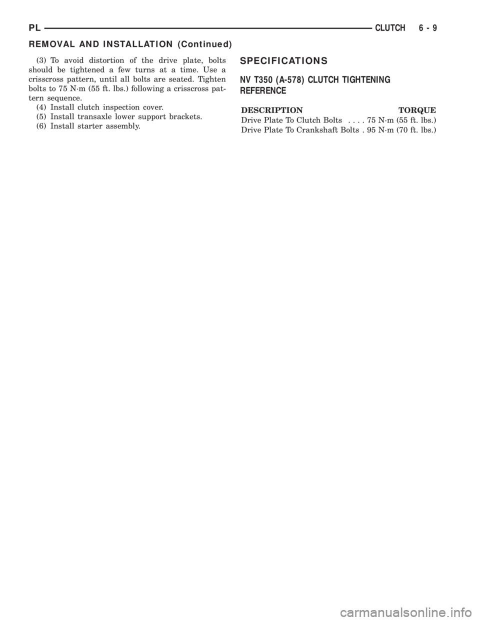
(3) To avoid distortion of the drive plate, bolts
should be tightened a few turns at a time. Use a
crisscross pattern, until all bolts are seated. Tighten
bolts to 75 N´m (55 ft. lbs.) following a crisscross pat-
tern sequence.
(4) Install clutch inspection cover.
(5) Install transaxle lower support brackets.
(6) Install starter assembly.SPECIFICATIONS
NV T350 (A-578) CLUTCH TIGHTENING
REFERENCE
DESCRIPTION TORQUE
Drive Plate To Clutch Bolts....75N´m(55ft.lbs.)
Drive Plate To Crankshaft Bolts . 95 N´m (70 ft. lbs.)
PLCLUTCH 6 - 9
REMOVAL AND INSTALLATION (Continued)
Page 716 of 1200
HONING CYLINDER BORES
(1) Used carefully, the cylinder bore resizing hone
C-823 equipped with 220 grit stones, is the best tool
for this job. In addition to deglazing, it will reduce
taper and out-of-round as well as removing light
scuffing, scoring or scratches. Usually a few strokes
will clean up a bore and maintain the required lim-
its.
(2) Deglazing of the cylinder walls may be done
using a cylinder surfacing hone, Tool C-3501,
equipped with 280 grit stones, if the cylinder bore is
straight and round. 20-60 strokes depending on the
bore condition, will be sufficient to provide a satisfac-
tory surface. Inspect cylinder walls after each 20
strokes, using a light honing oil.Do not use engine
or transmission oil, mineral spirits or kerosene.
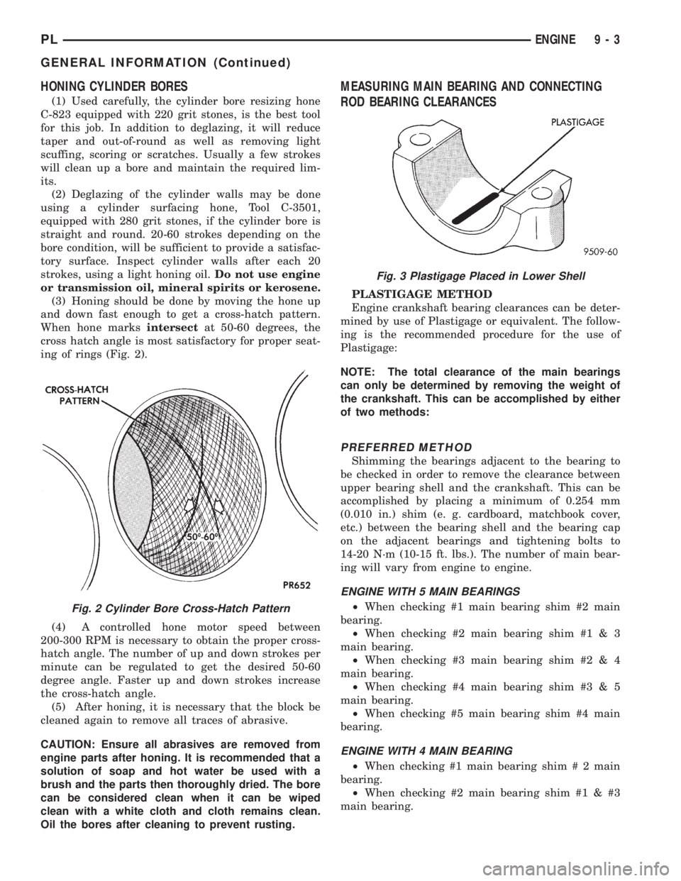
(3) Honing should be done by moving the hone up
and down fast enough to get a cross-hatch pattern.
When hone marksintersectat 50-60 degrees, the
cross hatch angle is most satisfactory for proper seat-
ing of rings (Fig. 2).
(4) A controlled hone motor speed between
200-300 RPM is necessary to obtain the proper cross-
hatch angle. The number of up and down strokes per
minute can be regulated to get the desired 50-60
degree angle. Faster up and down strokes increase
the cross-hatch angle.
(5) After honing, it is necessary that the block be
cleaned again to remove all traces of abrasive.
CAUTION: Ensure all abrasives are removed from
engine parts after honing. It is recommended that a
solution of soap and hot water be used with a
brush and the parts then thoroughly dried. The bore
can be considered clean when it can be wiped
clean with a white cloth and cloth remains clean.
Oil the bores after cleaning to prevent rusting.
MEASURING MAIN BEARING AND CONNECTING
ROD BEARING CLEARANCES
PLASTIGAGE METHOD
Engine crankshaft bearing clearances can be deter-
mined by use of Plastigage or equivalent. The follow-
ing is the recommended procedure for the use of
Plastigage:
NOTE: The total clearance of the main bearings
can only be determined by removing the weight of
the crankshaft. This can be accomplished by either
of two methods:
PREFERRED METHOD
Shimming the bearings adjacent to the bearing to
be checked in order to remove the clearance between
upper bearing shell and the crankshaft. This can be
accomplished by placing a minimum of 0.254 mm
(0.010 in.) shim (e. g. cardboard, matchbook cover,
etc.) between the bearing shell and the bearing cap
on the adjacent bearings and tightening bolts to
14-20 N´m (10-15 ft. lbs.). The number of main bear-
ing will vary from engine to engine.
ENGINE WITH 5 MAIN BEARINGS
²When checking #1 main bearing shim #2 main
bearing.
²When checking #2 main bearing shim #1 & 3
main bearing.
²When checking #3 main bearing shim #2 & 4
main bearing.
²When checking #4 main bearing shim #3 & 5
main bearing.
²When checking #5 main bearing shim #4 main
bearing.
ENGINE WITH 4 MAIN BEARING
²When checking #1 main bearing shim # 2 main
bearing.
²When checking #2 main bearing shim #1 & #3
main bearing.
Fig. 2 Cylinder Bore Cross-Hatch Pattern
Fig. 3 Plastigage Placed in Lower Shell
PLENGINE 9 - 3
GENERAL INFORMATION (Continued)