1999 DODGE NEON service reset
[x] Cancel search: service resetPage 55 of 1200

(7) Remove carpet (if required) from top of strut
tower. Then remove rubber dust shield (Fig. 8) from
top of strut tower, this will allow easier access to
upper strut mount attaching nuts.
(8) Loosen but do not remove the 4 upper strut
mount to strut tower attaching nuts (Fig. 9). Then
while supporting the strut assembly fully remove the
4 strut mount attaching nuts.
(9) Remove strut assembly from knuckle, by slid-
ing knuckle out of clevis bracket on strut assembly.
Then remove strut assembly from vehicle.
INSTALL
(1) Position strut assembly back into vehicle with
the 4 studs on strut mount assembly through holes
in strut tower of vehicle. Install the 4 strut mount to
body attaching nuts (Fig. 9) onto mount studs.
Torque the 4 strut mount to body attaching nuts to
34 N´m (300 in. lbs).(2) Install dust shield into hole on top of strut
tower (Fig. 8). Install carpeting back on top of rear
strut tower.
(3) Raise vehicle.
CAUTION: The knuckle to strut assembly attaching
bolts are serrated and must not be turned during
installation. Install and torque nuts while holding
bolts stationary in knuckle.
(4) Install knuckle assembly into clevis bracket on
strut assembly. Install the 2 clevis bracket to knuckle
assembly attaching bolts and nuts (Fig. 7). Torque
both clevis bracket to knuckle assembly attaching
nuts to 95 N´m (70 ft. lbs.).
(5) Install hydraulic flex hose bracket, on strut
assembly bracket (Fig. 6). Install and securely
tighten bolt attaching hose bracket to strut bracket.
If vehicle is equipped with Anti-Lock brakes, the
wheel speed sensor cable routing clip is also attached
to the strut assembly bracket.
(6) Install wheel and tire assembly on vehicle.
Tighten the wheel mounting stud nuts in proper
sequence until all nuts are torqued to half specifica-
tion. Then repeat tightening sequence to full speci-
fied torque of 135 N´m (100 ft. lbs.).
(7) Lower vehicle to the ground.
(8) Check and reset rear wheel TOE to specifica-
tions if required. Refer to Front And Rear Toe Setting
Procedure in the Wheel Alignment Check And
Adjustment section in this group of the service man-
ual for the required Toe setting procedure.
COIL SPRING
Coil springs are rated separately for each side of
vehicle depending on optional equipment and type of
service. During service procedures where both
springs are removed, mark springs (Chalk, Tape,
etc.) (Fig. 10) to ensure installation in original posi-
tion. If the coils springs require replacement.Be
sure that the springs needing replacement, are
replaced with springs meeting the correct load
and spring rate for the vehicle.
NOTE: During service procedures requiring
removal or installation of a coil spring with Spring
Compressor, Special Tool C-4838. It is required that
the first full top and bottom coil of the coil spring
be captured by the jaws of spring compressor (Fig.
10).
Replacement of the coil spring requires removal of
the strut assembly from the vehicle, and the disas-
sembly of the strut. Refer to strut assembly in the
removal and installation section in this group of the
service manual for the required removal and replace-
ment procedure for the strut assembly. Then refer to
Fig. 8 Dust Shield Removal From Strut Tower
Fig. 9 Strut Mount Attaching Nuts
2 - 44 SUSPENSIONPL
REMOVAL AND INSTALLATION (Continued)
Page 59 of 1200

(4) Install tension strut bushing, tension strut
retainer and nut on tension strut (Fig. 21).When
installing tension strut retainers, the retainers
must be installed on tension strut, with cupped
side of retainer facing away from bushing and
knuckle (Fig. 21).
(5) Position a large adjustable wrench on flat of
tension strut to keep it from turning, (Fig. 22) and
then torque tension strut nut to 95 N´m (70 ft. lbs.).
(6) On vehicles equipped with rear drum brakes,
install rear brake support plate assembly onto the
knuckle (Fig. 17). Install the 4 bolts (Fig. 17) attach-
ing rear brake support plate to rear knuckle. Torque
attaching bolts to 68 N´m (50 ft. lbs.).
(7) On vehicles equipped with rear disc brakes,
install the disc brake adapter on knuckle (Fig. 18)
Install the 4 bolts attaching the disc brake adapter to
knuckle (Fig. 18). Torque attaching bolts to 68 N´m
(50 ft. lbs.).(8) If vehicle is equipped with ABS brakes, install
speed sensor head into rear brake support plate or
disc brake adapter (Fig. 15). Tighten wheel speed
sensor mounting bolt to a torque of 7 N´m (60 in.
lbs.).
CAUTION: The hub/bearing retaining nut must be
tightened to but must not exceed its required
torque specification. The proper torque specifica-
tion of the retaining nut is critical to the life of the
hub bearing.
(9) Install rear hub and bearing assembly on
knuckle. Install hub and bearing assembly retaining
nut (Fig. 16), and torque to 217 N´m (160 ft. lbs).
(10) If vehicle is equipped with rear disc brakes,
install rear braking disc on hub. If vehicle is
equipped with rear drum brakes, install the brake
drum on hub.
(11) If vehicle is equipped with rear disc brakes,
install rear braking disc on hub. Carefully install
rear brake caliper over braking disc and install on
adapter. Tighten the caliper assembly to adapter
mounting bolts to 22 N´m (192 in. lbs.). Refer to Rear
Disc Brakes in Group 5 Brakes in this service man-
ual for required caliper installation procedure.
(12) Install wheel and tire assembly on vehicle.
Tighten the wheel mounting stud nuts in proper
sequence until all nuts are torqued to half specifica-
tion. Then repeat the tightening sequence to the full
specified torque of 135 N´m (100 ft. lbs.).
(13) Lower vehicle.
(14) With suspension supporting total weight of
vehicle, and lateral links at correct curb height,
torque both lateral link attaching bolts to 95 N´m (70
ft. lbs.).
(15) Check and reset rear wheel TOE to specifica-
tions if required. Refer to Front And Rear Toe Setting
Procedure in the Wheel Alignment Check And
Adjustment section in this group of the service man-
ual for the required Toe setting procedure.
LATERAL LINKS
The rear suspension lateral links (Fig. 23) are only
serviced as complete assemblies. The isolator bush-
ings used in the lateral links are not serviced as sep-
arate components. The rear lateral link assemblies
are unique, having different size bushings to accom-
modate the rear Toe adjustment cams. The rearward
lateral links, must be installed with small bushing
sleeve at knuckle and large bushing sleeve at rear
crossmember. This is required to accommodate the
rear Toe adjustment cam.
REMOVE
(1) Raise vehicle on jackstands or centered on a
frame contact type hoist. See Hoisting in the Lubri-
Fig. 21 Tension Strut Bushings Installed On Tension
Strut
Fig. 22 Torquing Tension Strut Nut
2 - 48 SUSPENSIONPL
REMOVAL AND INSTALLATION (Continued)
Page 61 of 1200
link mounting bolt at crossmember MUST be
installed, with head of bolt facing rear of vehi-
cle. The long attaching bolt must be used at
rear crossmember and short bolt used at
knuckle.
(1) Install washer on short lateral link attaching
bolt. Then install short lateral link attaching bolt,
into lateral link having the same size bushing
sleeves. Then install lateral link, bolt and washer
onto knuckle as an assembly, with head of bolt facing
to front of vehicle (Fig. 24).
(2) Install lateral link with small and large bush-
ing sleeve, on lateral link attaching bolt in rear
knuckle (Fig. 24).Small bushing sleeve must be
installed on bolt in rear knuckle with large
bushing sleeve at crossmember of vehicle.
(3) Install washer and nut onto lateral link attach-
ing bolt at rear knuckle (Fig. 24).Do not tighten
the lateral link to rear knuckle attaching bolt
at this time.
(4) Install Toe adjustment cam on long lateral link
attaching bolt. Install long lateral link attaching bolt
and adjustment cam, into lateral link toward rear of
vehicle, having the large bushing sleeve. Then pass
lateral link attaching bolt into rear crossmember
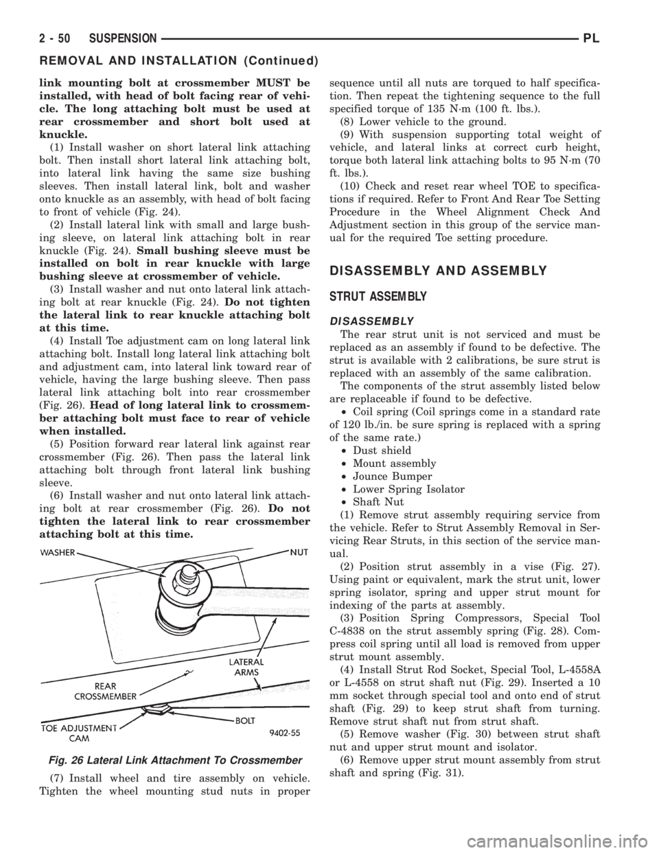
(Fig. 26).Head of long lateral link to crossmem-
ber attaching bolt must face to rear of vehicle
when installed.
(5) Position forward rear lateral link against rear
crossmember (Fig. 26). Then pass the lateral link
attaching bolt through front lateral link bushing
sleeve.
(6) Install washer and nut onto lateral link attach-
ing bolt at rear crossmember (Fig. 26).Do not
tighten the lateral link to rear crossmember
attaching bolt at this time.
(7) Install wheel and tire assembly on vehicle.
Tighten the wheel mounting stud nuts in propersequence until all nuts are torqued to half specifica-
tion. Then repeat the tightening sequence to the full
specified torque of 135 N´m (100 ft. lbs.).
(8) Lower vehicle to the ground.
(9) With suspension supporting total weight of
vehicle, and lateral links at correct curb height,
torque both lateral link attaching bolts to 95 N´m (70
ft. lbs.).
(10) Check and reset rear wheel TOE to specifica-
tions if required. Refer to Front And Rear Toe Setting
Procedure in the Wheel Alignment Check And
Adjustment section in this group of the service man-
ual for the required Toe setting procedure.
DISASSEMBLY AND ASSEMBLY
STRUT ASSEMBLY
DISASSEMBLY
The rear strut unit is not serviced and must be
replaced as an assembly if found to be defective. The
strut is available with 2 calibrations, be sure strut is
replaced with an assembly of the same calibration.
The components of the strut assembly listed below
are replaceable if found to be defective.
²Coil spring (Coil springs come in a standard rate
of 120 lb./in. be sure spring is replaced with a spring
of the same rate.)
²Dust shield
²Mount assembly
²Jounce Bumper
²Lower Spring Isolator
²Shaft Nut
(1) Remove strut assembly requiring service from
the vehicle. Refer to Strut Assembly Removal in Ser-
vicing Rear Struts, in this section of the service man-
ual.
(2) Position strut assembly in a vise (Fig. 27).
Using paint or equivalent, mark the strut unit, lower
spring isolator, spring and upper strut mount for
indexing of the parts at assembly.
(3) Position Spring Compressors, Special Tool
C-4838 on the strut assembly spring (Fig. 28). Com-
press coil spring until all load is removed from upper
strut mount assembly.
(4) Install Strut Rod Socket, Special Tool, L-4558A
or L-4558 on strut shaft nut (Fig. 29). Inserted a 10
mm socket through special tool and onto end of strut
shaft (Fig. 29) to keep strut shaft from turning.
Remove strut shaft nut from strut shaft.
(5) Remove washer (Fig. 30) between strut shaft
nut and upper strut mount and isolator.
(6) Remove upper strut mount assembly from strut
shaft and spring (Fig. 31).
Fig. 26 Lateral Link Attachment To Crossmember
2 - 50 SUSPENSIONPL
REMOVAL AND INSTALLATION (Continued)
Page 64 of 1200
mount and all tension is relieved from the spring
compressors.
(11) Install the strut assembly back into the vehi-
cle. Refer to Strut Assembly Removal in Servicing
Rear Struts in this section of the service manual.
(12) Check and reset rear wheel TOE to specifica-
tions if required.
STABILIZER BAR BUSHINGS
(1) If stabilizer bar to frame rail bushings require
replacement at time of inspection, install new bush-
ings before installing stabilizer bar. Bushings are
replaced by opening slit on bushings and peeling
them off stabilizer bar. Install new bushings on sta-
bilizer bar, by spreading bushing at slit and forcing
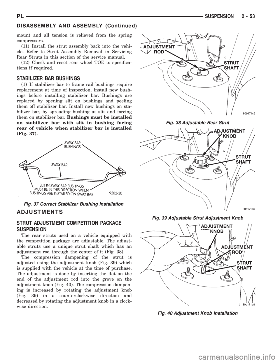
them on stabilizer bar.Bushings must be installed
on stabilizer bar with slit in bushing facing
rear of vehicle when stabilizer bar is installed
(Fig. 37).
ADJUSTMENTS
STRUT ADJUSTMENT COMPETITION PACKAGE
SUSPENSION
The rear struts used on a vehicle equipped with
the competition package are adjustable. The adjust-
able struts use a unique strut shaft which has an
adjustment rod through the center of it (Fig. 38).
The compression dampening of the strut is
adjusted using the adjustment knob (Fig. 39) which
is supplied with the vehicle at the time of purchase.
The adjustment is done by inserting the flat on the
end of the adjustment rod into the grove on the
adjustment knob (Fig. 40). The compression dampen-
ing is increased by rotating the adjustment knob
(Fig. 39) in a counterclockwise direction and
decreased by rotating the adjustment knob in a clock-
wise direction.
Fig. 37 Correct Stabilizer Bushing Installation
Fig. 38 Adjustable Rear Strut
Fig. 39 Adjustable Strut Adjustment Knob
Fig. 40 Adjustment Knob Installation
PLSUSPENSION 2 - 53
DISASSEMBLY AND ASSEMBLY (Continued)
Page 86 of 1200
operating cable configuration as the drum brake
equipped vehicles, but different cables.
PROPORTIONING VALVES
NON-ANTILOCK BRAKES
Proportioning valves balance front to rear braking
by controlling at a given ratio, the increase in rear
brake system hydraulic pressure above a preset level
(split point). Under light pedal application, the pro-portioning valve allows full hydraulic pressure to be
applied to the rear brakes.
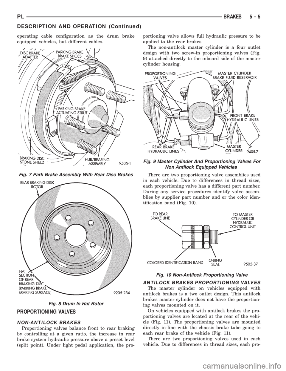
The non-antilock master cylinder is a four outlet
design with two screw-in proportioning valves (Fig.
9) attached directly to the inboard side of the master
cylinder housing.
There are two proportioning valve assemblies used
in each vehicle. Due to differences in thread sizes,
each proportioning valve has a different part number.
During any service procedures identify valve assem-
blies by supplier part number and or the color iden-
tification band (Fig. 10).
ANTILOCK BRAKES PROPORTIONING VALVES
The master cylinder on vehicles equipped with
antilock brakes is a two outlet design. This antilock
brakes master cylinder does not have the proportion-
ing valves mounted on it.
On vehicles equipped with antilock brakes the pro-
portioning valves are located at the rear of the vehi-
cle (Fig. 11). The proportioning valves are mounted
directly in-line with the chassis brake tube going to
each rear brake of the vehicle (Fig. 11).
There are two proportioning valves used in each
vehicle. Due to differences in thread sizes, each pro-
Fig. 7 Park Brake Assembly With Rear Disc Brakes
Fig. 8 Drum In Hat Rotor
Fig. 9 Master Cylinder And Proportioning Valves For
Non Antilock Equipped Vehicles
Fig. 10 Non-Antilock Proportioning Valve
PLBRAKES 5 - 5
DESCRIPTION AND OPERATION (Continued)
Page 172 of 1200
CLUTCH
CONTENTS
page page
GENERAL INFORMATION
CLUTCH COMPONENTS................... 1
CLUTCH DISC AND COVER APPLICATION.... 2
CLUTCH REPLACEMENT.................. 2
DESCRIPTION AND OPERATION
CLUTCH CABLE......................... 2
CLUTCH PEDAL POSITION SWITCH......... 2
DIAGNOSIS AND TESTING
CLASH±INTO±REVERSE COMPLAINTS....... 6
CLUTCH CHATTER COMPLAINTS........... 6
CLUTCH COVER AND DISC RUNOUT........ 6
CLUTCH DIAGNOSIS..................... 3
CLUTCH PEDAL POSITION SWITCH......... 2
DRIVE PLATE MISALIGNMENT............. 6
REMOVAL AND INSTALLATION
CLUTCH ASSEMBLY...................... 7CLUTCH CABLE......................... 6
CLUTCH PEDAL POSITION SWITCH......... 7
RELEASE BEARING AND FORK............. 9
CLEANING AND INSPECTION
CLEANING PRECAUTIONS................ 10
CLUTCH CONTAMINATION................ 10
ADJUSTMENTS
CLUTCH CABLE........................ 10
CLUTCH PEDAL POSITION SWITCH........ 11
SPECIFICATIONS
TORQUE.............................. 11
SPECIAL TOOLS
CLUTCH.............................. 11
GENERAL INFORMATION
CLUTCH COMPONENTS
NOTE: Neon vehicles produced at the Toluca
assembly plant, in Mexico, have conventional clutch
and flywheel assemblies. Vehicles produced at Bel-
videre assembly plant have modular clutch assem-
blies.
Before beginning clutch service, check the 11th
character of the V.I.N. to determine where it was
produced. The 11th character is ªDº for vehicles
produced at Belvidere, or ªTº for vehicles produced
at Toluca.
For a vehicle produced at Belvidere assembly,
refer to this manual for service information on the
modular clutch assembly. For a vehicle produced at
Toluca assembly, refer to the following information
to determine proper service procedures.
Service parts stock only a Conventional Clutch
Disc Assembly or a Modular Clutch Service Pack-
age to service Toluca built vehicles. The Modular
Clutch Service Package contains the following
parts:
²One modular clutch assembly
²One drive plate assembly
²One backing plate assembly
²Four drive plate to clutch bolts
²Eight drive plate to crankshaft boltsIf only the clutch disc requires replacement,
obtain the clutch disc. Replace the clutch disc
using the information in the Removal And Installa-
tion section of this manual.
If the clutch pressure plate or flywheel requires
replacement, obtain the Modular Clutch Service
Package. Refer to this manual for service informa-
tion on the modular clutch assembly.
The clutch assembly used in this vehicle consists of
a single, dry-type clutch disc and a diaphragm style
clutch cover.
The clutch disc has cushion springs riveted to the
disc hub assembly. The clutch disc facings are riveted
to the cushion springs. The facings are made from a
non-asbestos material.
The clutch cover pressure plate assembly is a dia-
phragm type unit with a one-piece diaphragm spring
with multiple release fingers. The pressure plate
release fingers are preset during manufacture and
are not adjustable.
A sleeve-type release bearing is used to engage and
disengage the clutch cover pressure plate. The bear-
ing is prelubed during manufacture and is a sealed
unit.
The release bearing is operated by a pivoting
release fork in the clutch housing. The fork pivots on
a ball stud within the housing. The release fork is
actuated by a self-adjusting clutch cable.
PLCLUTCH 6 - 1
Page 184 of 1200
CLUTCH
CONTENTS
page page
GENERAL INFORMATION
CLUTCH COMPONENTS Ð RIGHT HAND
DRIVE (RHD)........................ 1
CLUTCH DISC AND COVER APPLICATION Ð
RIGHT HAND DRIVE (RHD)............. 1
CLUTCH REPLACEMENT Ð RIGHT HAND
DRIVE (RHD)........................ 1
DESCRIPTION AND OPERATION
CLUTCH PEDAL POSITION SWITCH Ð RIGHT
HAND DRIVE (RHD)................... 2
HYDRAULIC CLUTCH SYSTEM Ð RIGHT
HAND DRIVE (RHD)................... 2
DIAGNOSIS AND TESTING
CLASH±INTO±REVERSE COMPLAINTS...... 6CLUTCH DIAGNOSIS Ð RIGHT HAND DRIVE
(RHD).............................. 2
REMOVAL AND INSTALLATION
CLUTCH ASSEMBLY Ð RIGHT HAND DRIVE
(RHD).............................. 8
CLUTCH MASTER CYLINDER Ð RIGHT HAND
DRIVE (RHD)........................ 6
CLUTCH PEDAL POSITION SWITCH Ð RIGHT
HAND DRIVE (RHD)................... 8
HYDRAULIC SLAVE CYLINDER Ð RIGHT
HAND DRIVE (RHD)................... 7
SPECIFICATIONS
NV T350 (A-578) CLUTCH TIGHTENING
REFERENCE.......................... 9
GENERAL INFORMATION
CLUTCH COMPONENTS Ð RIGHT HAND DRIVE
(RHD)
The modular clutch assembly used in this vehicle
consists of a single, dry-type clutch disc and a dia-
phragm style clutch cover.
The clutch disc has cushion springs riveted to the
disc hub assembly. The clutch disc facings are riveted
to the cushion springs. The facings are made from a
non-asbestos material.
The clutch cover pressure plate assembly is a dia-
phragm type unit with a one-piece diaphragm spring
with multiple release fingers. The pressure plate
release fingers are preset during manufacture and
are not adjustable.
A sleeve-type release bearing is used to engage and
disengage the clutch cover pressure plate. The bear-
ing is prelubed during manufacture and is a sealed
unit.
The release bearing is operated by a pivoting
release fork in the clutch housing. The fork pivots on
a ball stud within the housing. The release fork is
actuated by a hydraulic clutch system.
The hydraulic clutch automatically adjusts for any
slack in the mechanism. This compensates for clutch
disc wear. The system requires no maintenance or
lubrication.
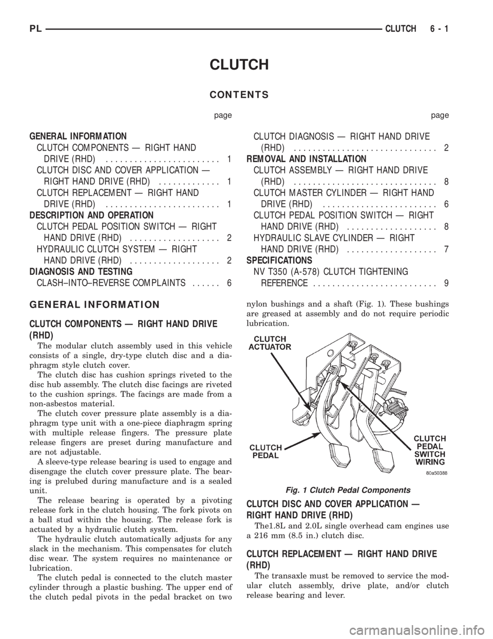
The clutch pedal is connected to the clutch master
cylinder through a plastic bushing. The upper end of
the clutch pedal pivots in the pedal bracket on twonylon bushings and a shaft (Fig. 1). These bushings
are greased at assembly and do not require periodic
lubrication.
CLUTCH DISC AND COVER APPLICATION Ð
RIGHT HAND DRIVE (RHD)
The1.8L and 2.0L single overhead cam engines use
a 216 mm (8.5 in.) clutch disc.
CLUTCH REPLACEMENT Ð RIGHT HAND DRIVE
(RHD)
The transaxle must be removed to service the mod-
ular clutch assembly, drive plate, and/or clutch
release bearing and lever.
Fig. 1 Clutch Pedal Components
PLCLUTCH 6 - 1
Page 305 of 1200
(c) If continuity is OK between cavity 62 and
cavity 1, repair open circuit between cavity 2 of the
stop lamp switch connector and ground.
(6) Using an ohmmeter, check continuity from cav-
ity 76 on PCM connector to ground with the trans-
mission in park or neutral. If no continuity, test TRS/
Park-Neutral switch and switch wiring
(7) Turn speed control and ignition switch OFF.
(8) Unplug the BLACK 40-way connector from the
Powertrain Control Module (PCM)
(9) Using an ohmmeter, check continuity from cav-
ity 3 of servo connector to cavity 5 on the PCM con-
nector.
(a) If continuity is OK, replace PCM. Check cir-
cuit for short to ground before replacing PCM.
(b) If no continuity, remove stop lamp switch
and conduct Stop Lamp Switch Test. If test fails,
adjust or replace as necessary.
(c) If switch passes, measure continuity from
cavity 4 of stop lamp switch connector to cavity 3
of servo connector. Repair open circuit if necessary.
(d) If continuity is OK, measure continuity from
cavity 3 of stop lamp switch to cavity 5 of PCM
connector. Repair open circuit as necessary.
(e) Install PCM connectors onto PCM and speed
control servo connector to servo.
VACUUM SUPPLY TEST
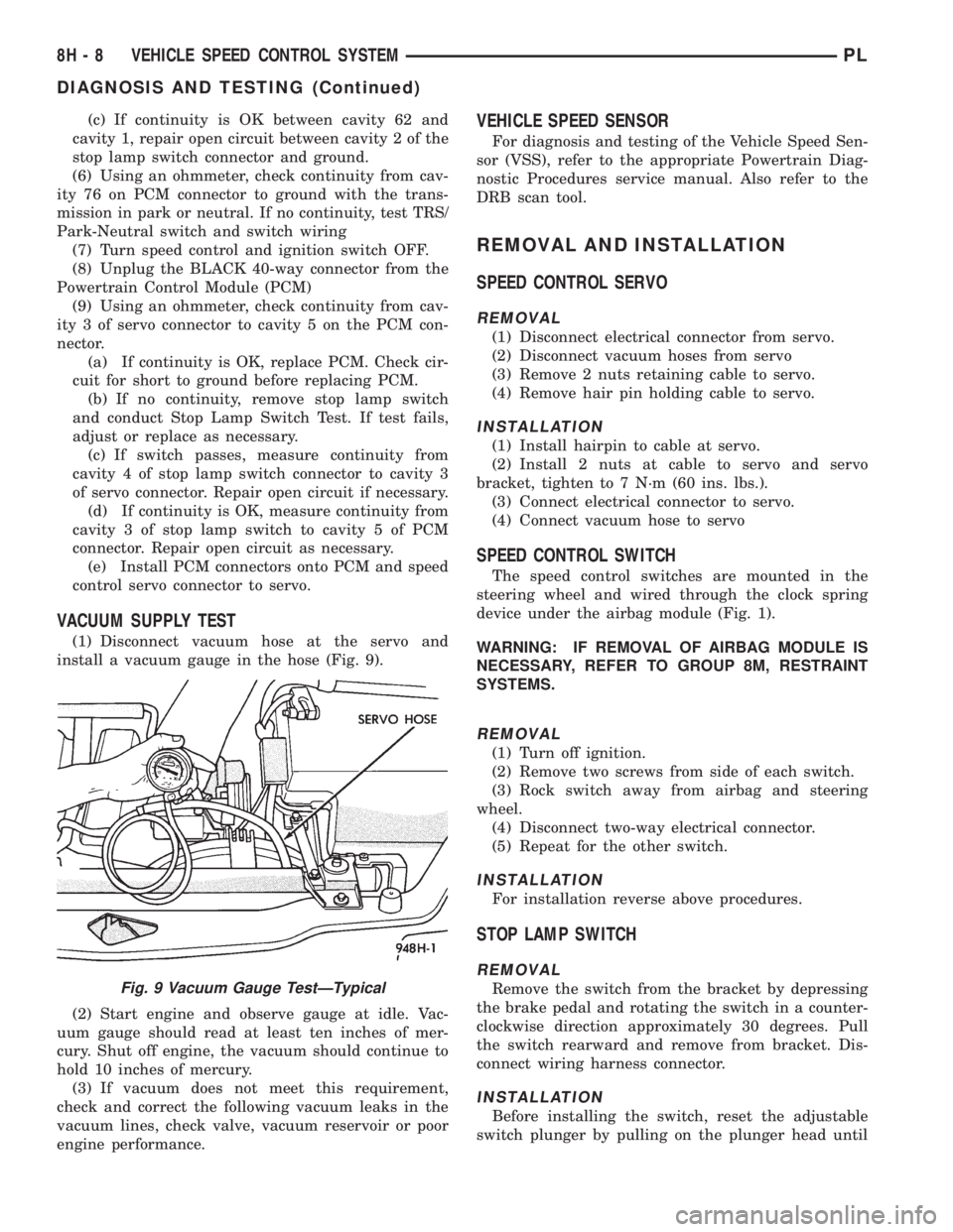
(1) Disconnect vacuum hose at the servo and
install a vacuum gauge in the hose (Fig. 9).
(2) Start engine and observe gauge at idle. Vac-
uum gauge should read at least ten inches of mer-
cury. Shut off engine, the vacuum should continue to
hold 10 inches of mercury.
(3) If vacuum does not meet this requirement,
check and correct the following vacuum leaks in the
vacuum lines, check valve, vacuum reservoir or poor
engine performance.
VEHICLE SPEED SENSOR
For diagnosis and testing of the Vehicle Speed Sen-
sor (VSS), refer to the appropriate Powertrain Diag-
nostic Procedures service manual. Also refer to the
DRB scan tool.
REMOVAL AND INSTALLATION
SPEED CONTROL SERVO
REMOVAL
(1) Disconnect electrical connector from servo.
(2) Disconnect vacuum hoses from servo
(3) Remove 2 nuts retaining cable to servo.
(4) Remove hair pin holding cable to servo.
INSTALLATION
(1) Install hairpin to cable at servo.
(2) Install 2 nuts at cable to servo and servo
bracket, tighten to 7 N´m (60 ins. lbs.).
(3) Connect electrical connector to servo.
(4) Connect vacuum hose to servo
SPEED CONTROL SWITCH
The speed control switches are mounted in the
steering wheel and wired through the clock spring
device under the airbag module (Fig. 1).
WARNING: IF REMOVAL OF AIRBAG MODULE IS
NECESSARY, REFER TO GROUP 8M, RESTRAINT
SYSTEMS.
REMOVAL
(1) Turn off ignition.
(2) Remove two screws from side of each switch.
(3) Rock switch away from airbag and steering
wheel.
(4) Disconnect two-way electrical connector.
(5) Repeat for the other switch.
INSTALLATION
For installation reverse above procedures.
STOP LAMP SWITCH
REMOVAL
Remove the switch from the bracket by depressing
the brake pedal and rotating the switch in a counter-
clockwise direction approximately 30 degrees. Pull
the switch rearward and remove from bracket. Dis-
connect wiring harness connector.
INSTALLATION
Before installing the switch, reset the adjustable
switch plunger by pulling on the plunger head until
Fig. 9 Vacuum Gauge TestÐTypical
8H - 8 VEHICLE SPEED CONTROL SYSTEMPL
DIAGNOSIS AND TESTING (Continued)