1999 DODGE NEON brake light
[x] Cancel search: brake lightPage 4 of 1200
MAINTENANCE SCHEDULES
INDEX
page page
GENERAL INFORMATION
INTRODUCTION......................... 3
SCHEDULE ± A.......................... 3SCHEDULE ± B.......................... 4
UNSCHEDULED INSPECTION............... 3
GENERAL INFORMATION
INTRODUCTION
Service and maintenance procedures for compo-
nents and systems listed in Schedule ± A or B can be
found by using the Group Tab Locator index at the
front of this manual. If it is not clear which group
contains the information needed, refer to the index at
the back of this manual.
There are two maintenance schedules that show
proper service based on the conditions that the vehi-
cle is subjected to. Use the schedule that best
describes these conditions.
Schedule ±A, lists maintenance recommended for
vehicles used for general transportation.
Schedule ±B, lists maintenance recommended for
vehicles used under the following conditions:
²Frequent short trip driving less than 5 miles (8
km)
²Frequent driving in dusty conditions
²Frequent trailer towing
²Extensive idling
²More than 50% of your driving is at sustained
high speeds during hot weather, above 90ÉF (32ÉC)
Where time and mileage are listed, follow the
interval that occurs first.
EMISSION CONTROL SYSTEM MAINTENANCE
The scheduled emission maintenance listed inbold
typeon the Maintenance Schedules, must be done at
the mileage specified to assure the continued proper
functioning of the emission control system. These,
and all other maintenance services included in this
manual, should be done to provide the best vehicle
performance and reliability. More frequent mainte-
nance may be needed for vehicles in severe operating
conditions such as dusty areas and very short trip
driving.
UNSCHEDULED INSPECTION
At Each Stop For Fuel
²Check engine oil level, add as required.
²Check windshield washer solvent and add if
required.
Once A Month
²Check tire pressure and look for unusual wear
or damage.
²Inspect battery, clean, and tighten terminals as
required.
²Check fluid levels of coolant reservoir, power
steering and automatic transmission and add as
required.
²Check all lights and all other electrical items for
correct operation.
At Each Oil Change
²Inspect exhaust system.
²Inspect brake hoses.
²Inspect the CV joints and front suspension com-
ponents.
²Rotate the tires at each oil change interval
shown on Schedule ± A (7,500 miles) or every other
interval shown on schedule ± B (6,000 miles).
²Check coolant level, hoses and clamps.
²Check the manual transaxle fluid level.
²If the mileage is less than 7,500 miles (12 000
km) yearly, replace the engine oil filter at each oil
change.
SCHEDULE ± A
7,500 Miles (12 000 km) or at 6 months
²Change engine oil.
15,000 Miles (24 000 km) or at 12 months
²Change engine oil.
²Replace engine oil filter.
²Adjust drive belt tension.
22,500 Miles (36 000 km) or at 18 months
²Change engine oil.
²Inspect the front brake pads and rear brake lin-
ings.
30,000 Miles (48 000 km) or at 24 months
²Change engine oil.
²Replace engine oil filter.
²Lubricate front suspension ball joints.
²Adjust drive belt tension.
PLLUBRICATION AND MAINTENANCE 0 - 3
Page 67 of 1200
the jounce and rebound travel of the front suspen-
sion.
On vehicles equipped with ABS brakes, the outer
C/V joint is equipped with a tone wheel used to
determine vehicle speed for ABS brake operation.
The inner tripod joint of both driveshafts is splined
into the transaxle side gears. The inner tripod joints
are retained in the side gears of the transaxle using
a snap ring located in the stub shaft of the tripod
joint. The outer C/V joint has a stub shaft that is
splined into the wheel hub and retained by a hub nut
using a nut lock and cotter pin.
NOTE: This vehicle does not use a rubber±lip bear-
ing seal as on previous front±wheel±drive cars to
prevent contamination of the front wheel bearing.
On these vehicles, the face of the outer C/V joint
fits deeply into the steering knuckle, using a close
outer C/V joint±to±steering knuckle fit. This design
deters direct water splash on bearing seal while
allowing any water that gets in, to run out the bot-
tom of the steering knuckle bearing bore. It is
important to thoroughly clean the outer C/V joint
and the wheel bearing area in the steering knuckle
before it is assembled after servicing.
DIAGNOSIS AND TESTING
DRIVESHAFT DIAGNOSIS
VEHICLE INSPECTION
(1) Check for grease in the vicinity of the inboard
tripod joint and outboard C/V joint; this is a sign of
inner or outer joint seal boot or seal boot clamp dam-
age.
(2) A light film of grease may appear on the right
inner tripod joint seal boot; this is considered normal
and should not require replacement of the seal boot.
The right inner tripod joint seal boot is made of sili-
cone rubber; which will allow the weeping (sweating)
of the joint lubricant to pass through it while in oper-
ation.
NOISE AND/OR VIBRATION IN TURNS
A clicking noise and/or a vibration in turns could
be caused by one of the following conditions.
(1) Damaged outer C/V or inner tripod joint seal
boot or seal boot clamps. This will result in the loss
and/or contamination of the joint grease, resulting in
inadequate lubrication of the joint.
(2) Noise may also be caused by another compo-
nent of the vehicle coming in contact with the drive-
shafts.
CLUNKING NOISE DURING ACCELERATION
This noise may be a result of one of the following
conditions:
(1) A torn seal boot on the inner or outer joint of
the driveshaft assembly.
(2) A loose or missing clamp on the inner or outer
joint of the driveshaft assembly.
(3) A damaged or worn driveshaft C/V joint.
SHUDDER OR VIBRATION DURING
ACCELERATION
(1) A worn or damaged driveshaft inner tripod
joint.
(2) A sticking tripod joint spider assembly (inner
tripod joint only).
(3) Improper wheel alignment. See Wheel Align-
ment in this group for alignment checking and set-
ting procedures and specifications.
VIBRATION AT HIGHWAY SPEEDS
(1) Foreign material (mud, etc.) packed on the
backside of the wheel(s).
(2) Out of balance front tires or wheels. See Group
22, Wheels And Tires for the required balancing pro-
cedure.
(3) Improper tire and/or wheel runout. See Group
22, Wheels And Tires for the required runout check-
ing procedure.
REMOVAL AND INSTALLATION
FRONT DRIVESHAFTS
CAUTION: Boot sealing is vital to retain special
lubricants and to prevent foreign contaminants
from entering the C/V joint. Mishandling, such as
allowing the assemblies to dangle unsupported, or
pulling or pushing the ends can cut boots or dam-
age C/V joints. During removal and installation pro-
cedures, always support both ends of the driveshaft
to prevent damage.
REMOVAL
CAUTION: The driveshaft, when installed, acts as a
bolt and secures the front hub/bearing assembly. If
vehicle is to be supported or moved on its wheels
with a driveshaft removed, install a PROPER±SIZED
BOLT AND NUT through front hub. Tighten bolt and
nut to 203 N´m (150 ft. lbs.). This will ensure that
the hub bearing cannot loosen.
(1) Remove cotter pin, nut lock, and spring washer
(Fig. 2) from the end of the outer C/V joint stub axle.
(2) Loosen (but do not remove) stub axle±to±hub/
bearing retaining nut (Fig. 3). Loosen hub nut while
3 - 2 DIFFERENTIAL AND DRIVELINEPL
GENERAL INFORMATION (Continued)
Page 82 of 1200
BRAKES
CONTENTS
page page
ANTILOCK BRAKE SYSTEM±TEVES MARK 20 . 69
BASE BRAKE SYSTEM..................... 2GENERAL INFORMATION................... 1
GENERAL INFORMATION
INDEX
page
GENERAL INFORMATION
BASE BRAKE SYSTEM DESCRIPTION........ 1
GENERAL INFORMATION
BASE BRAKE SYSTEM DESCRIPTION
Typical brake equipment consists of:
²Double pin floating caliper disc front brakes.
²Rear automatic adjusting drum brakes.
²Brake Fluid Level Switch.
²Master cylinder.
²Vacuum power booster.
²Double pin floating caliper rear disc brakes are
available on some models.
²Hand operated auto adjust park brake lever.
²Front disc brake pads are semi-metallic.
Vehicles equipped with the optional antilock brake
system (ABS) use a system designated Mark 20 and
is supplied by Teves. This system shares the base
brake hardware with vehicles not equipped withABS. A vehicle equipped with ABS does however use
a different vacuum booster, master cylinder and
brake tubes. Also included in the ABS system is an
integrated control unit (ICU), four wheel speed sen-
sors, and an electronic controller referred to as the
controller antilock brakes (CAB). These components
will be described in detail in the Teves Mark 20 ABS
brake section in this group of the service manual.
The hydraulic brake system is diagonally split on
both the Non-ABS and ABS braking system. With the
left front and right rear brakes on one hydraulic sys-
tem and the right front and left rear on the other.
The master cylinder is anodized, lightweight alu-
minum. On vehicles equipped with front disc brakes
and rear drum brakes, the master cylinder bore is
21.0 mm. On vehicles equipped with four wheel disc
brakes, the master cylinder bore is 22.2 mm.
PLBRAKES 5 - 1
Page 86 of 1200
operating cable configuration as the drum brake
equipped vehicles, but different cables.
PROPORTIONING VALVES
NON-ANTILOCK BRAKES
Proportioning valves balance front to rear braking
by controlling at a given ratio, the increase in rear
brake system hydraulic pressure above a preset level
(split point). Under light pedal application, the pro-portioning valve allows full hydraulic pressure to be
applied to the rear brakes.
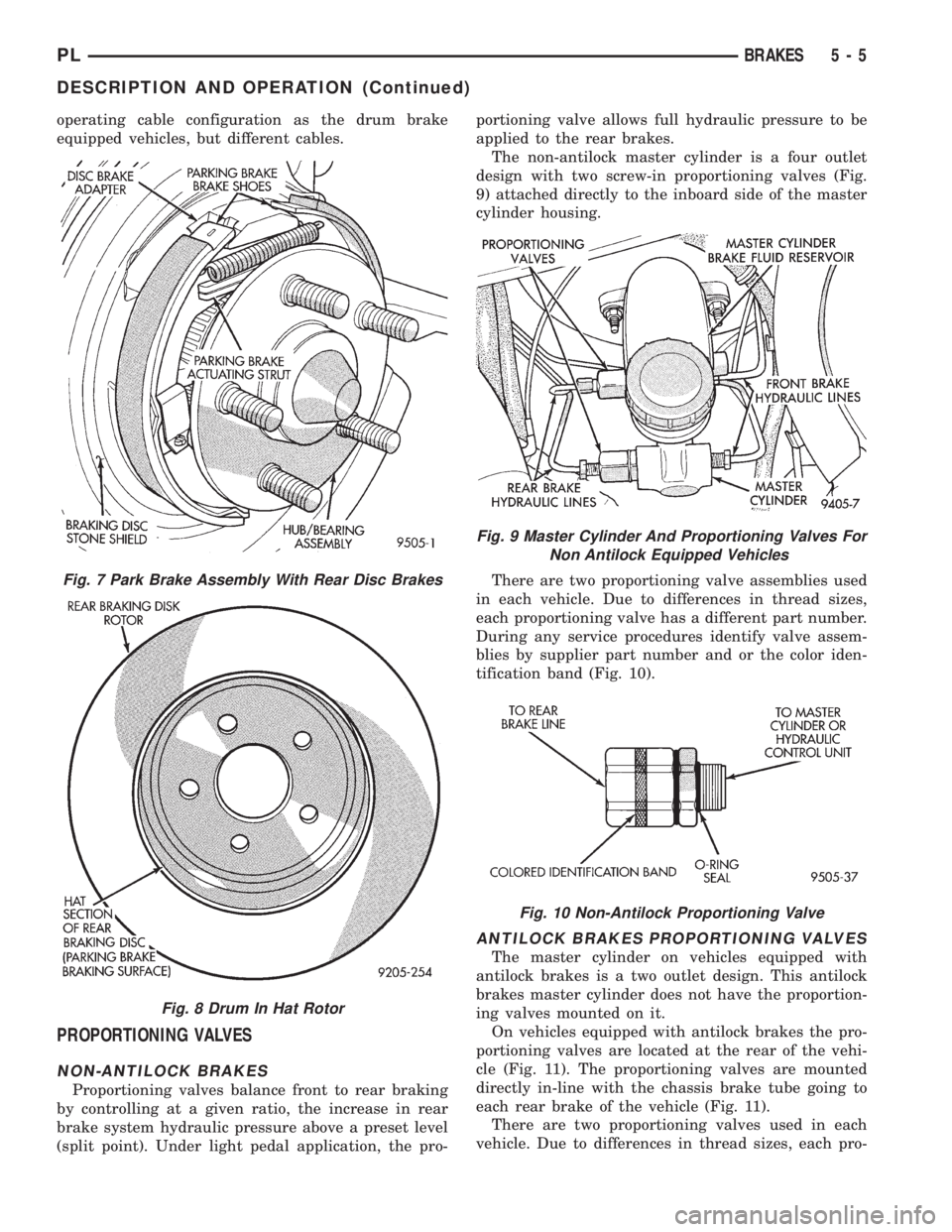
The non-antilock master cylinder is a four outlet
design with two screw-in proportioning valves (Fig.
9) attached directly to the inboard side of the master
cylinder housing.
There are two proportioning valve assemblies used
in each vehicle. Due to differences in thread sizes,
each proportioning valve has a different part number.
During any service procedures identify valve assem-
blies by supplier part number and or the color iden-
tification band (Fig. 10).
ANTILOCK BRAKES PROPORTIONING VALVES
The master cylinder on vehicles equipped with
antilock brakes is a two outlet design. This antilock
brakes master cylinder does not have the proportion-
ing valves mounted on it.
On vehicles equipped with antilock brakes the pro-
portioning valves are located at the rear of the vehi-
cle (Fig. 11). The proportioning valves are mounted
directly in-line with the chassis brake tube going to
each rear brake of the vehicle (Fig. 11).
There are two proportioning valves used in each
vehicle. Due to differences in thread sizes, each pro-
Fig. 7 Park Brake Assembly With Rear Disc Brakes
Fig. 8 Drum In Hat Rotor
Fig. 9 Master Cylinder And Proportioning Valves For
Non Antilock Equipped Vehicles
Fig. 10 Non-Antilock Proportioning Valve
PLBRAKES 5 - 5
DESCRIPTION AND OPERATION (Continued)
Page 89 of 1200

either through the park brake switch, the fluid level
sensor in the master cylinder reservoir, or the igni-
tion switch in the crank position.
The Brake Fluid Level sensor is located in the
brake fluid reservoir of the master cylinder assembly
(Fig. 18). The purpose of the sensor is to provide the
driver with an early warning that the brake fluid
level in the master cylinder reservoir has dropped to
below normal. This may indicate an abnormal loss of
brake fluid in the master cylinder fluid reservoir
resulting from a leak in the hydraulic system.
As the fluid drops below the minimum level, the
fluid level sensor closes the brake warning light cir-
cuit. This will turn on the red brake warning light.
At this time, master cylinder fluid reservoir shouldbe checked and filled to the full mark with DOT 3
brake fluid.If brake fluid level has dropped in
master cylinder fluid reservoir, the entire
brake hydraulic system should be checked for
evidence of a leak.
STOP LAMP SWITCH
The stop lamp switch controls operation of the
vehicles stop lamps. Also, if the vehicle is equipped
with speed control, the stop lamp switch will deacti-
vate speed control when the brake pedal is
depressed.
The stop lamp switch controls operation of the
right and left tail, stop and turn signal lamp and
CHMSL lamp, by supplying battery current to these
lamps.
The stop lamp switch controls the lamp operation
by opening and closing the electrical circuit to the
stop lamps.
REAR WHEEL HUB/BEARING
CAUTION: If a vehicle is equipped with antilock
brakes the tone wheels for the rear wheel speed
sensors are pressed onto the hub. The tone wheels
used on this vehicle equipped with the Teves Mark
20 Antilock Brake System are different then those
used on past models of this vehicle equipped with
antilock brakes. Reduced braking performance will
result if this part is used on earlier model vehicles
and an accident could result. Do not use on
pre-1998 model year vehicles.
All vehicles are equipped with permanently lubri-
cated and sealed for life rear wheel bearings. There
is no periodic lubrication or maintenance recom-
mended for these units. However, if servicing of a
rear wheel bearing is required, refer to procedures in
the diagnosis and testing section and the removal
and installation section in this group of the service
manual for the inspection and replacement of the
rear wheel bearing.Fig. 17 Power Brake Booster Assembly
Fig. 18 Master Cylinder Fluid Level Sensor
5 - 8 BRAKESPL
DESCRIPTION AND OPERATION (Continued)
Page 90 of 1200
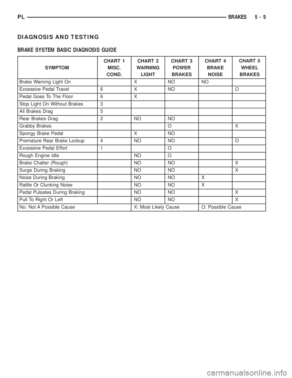
DIAGNOSIS AND TESTING
BRAKE SYSTEM BASIC DIAGNOSIS GUIDE
SYMPTOMCHART 1
MISC.
COND.CHART 2
WARNING
LIGHTCHART 3
POWER
BRAKESCHART 4
BRAKE
NOISECHART 5
WHEEL
BRAKES
Brake Warning Light On X NO NO
Excessive Pedal Travel 6 X NO O
Pedal Goes To The Floor 6 X
Stop Light On Without Brakes 3
All Brakes Drag 5
Rear Brakes Drag 2 NO NO
Grabby Brakes O X
Spongy Brake Pedal X NO
Premature Rear Brake Lockup 4 NO NO O
Excessive Pedal Effort 1 O
Rough Engine Idle NO O
Brake Chatter (Rough) NO NO X
Surge During Braking NO NO X
Noise During Braking NO NO X
Rattle Or Clunking Noise NO NO X
Pedal Pulsates During Braking NO NO X
Pull To Right Or Left NO NO X
No: Not A Possible Cause X: Most Likely Cause O: Possible Cause
PLBRAKES 5 - 9
Page 96 of 1200
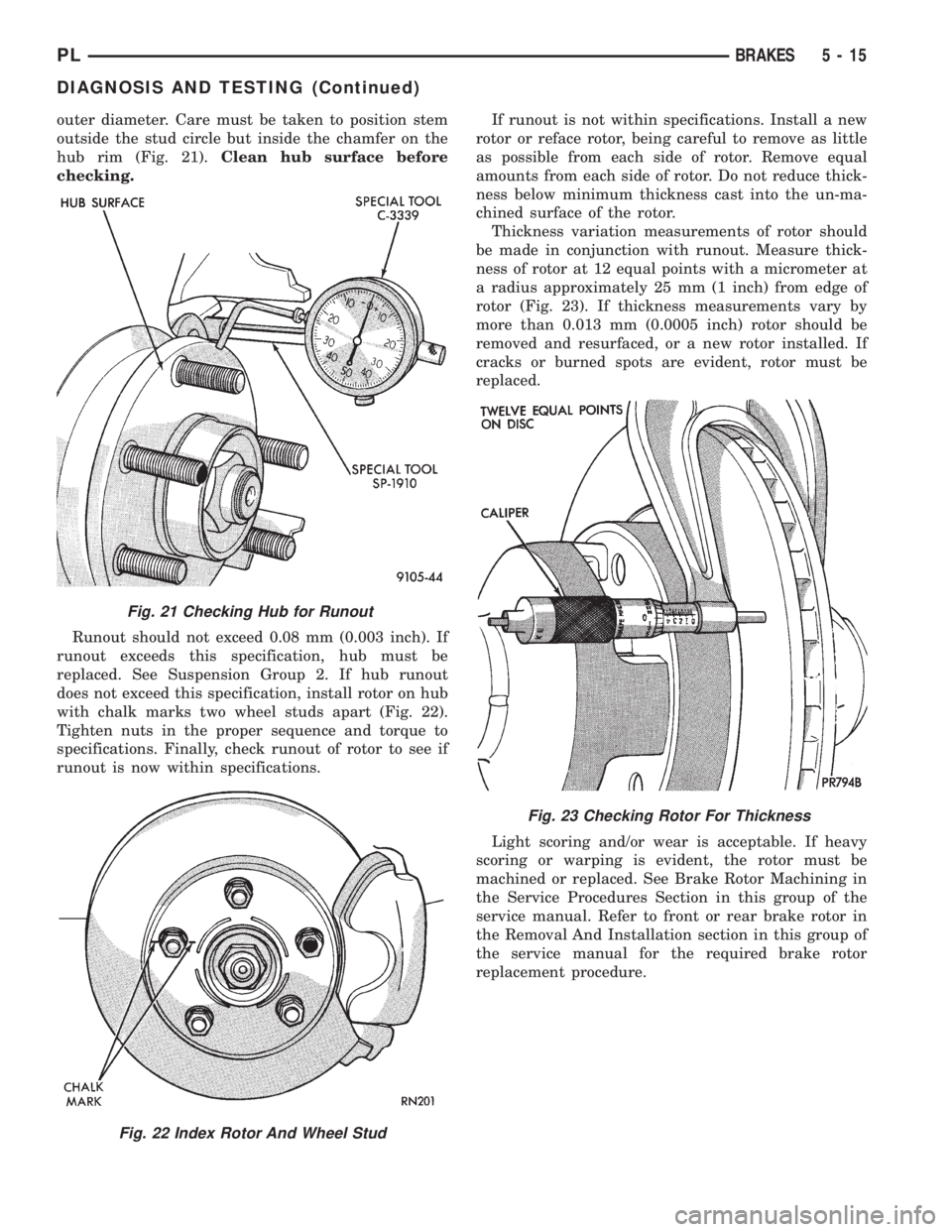
outer diameter. Care must be taken to position stem
outside the stud circle but inside the chamfer on the
hub rim (Fig. 21).Clean hub surface before
checking.
Runout should not exceed 0.08 mm (0.003 inch). If
runout exceeds this specification, hub must be
replaced. See Suspension Group 2. If hub runout
does not exceed this specification, install rotor on hub
with chalk marks two wheel studs apart (Fig. 22).
Tighten nuts in the proper sequence and torque to
specifications. Finally, check runout of rotor to see if
runout is now within specifications.If runout is not within specifications. Install a new
rotor or reface rotor, being careful to remove as little
as possible from each side of rotor. Remove equal
amounts from each side of rotor. Do not reduce thick-
ness below minimum thickness cast into the un-ma-
chined surface of the rotor.
Thickness variation measurements of rotor should
be made in conjunction with runout. Measure thick-
ness of rotor at 12 equal points with a micrometer at
a radius approximately 25 mm (1 inch) from edge of
rotor (Fig. 23). If thickness measurements vary by
more than 0.013 mm (0.0005 inch) rotor should be
removed and resurfaced, or a new rotor installed. If
cracks or burned spots are evident, rotor must be
replaced.
Light scoring and/or wear is acceptable. If heavy
scoring or warping is evident, the rotor must be
machined or replaced. See Brake Rotor Machining in
the Service Procedures Section in this group of the
service manual. Refer to front or rear brake rotor in
the Removal And Installation section in this group of
the service manual for the required brake rotor
replacement procedure.
Fig. 21 Checking Hub for Runout
Fig. 22 Index Rotor And Wheel Stud
Fig. 23 Checking Rotor For Thickness
PLBRAKES 5 - 15
DIAGNOSIS AND TESTING (Continued)
Page 100 of 1200
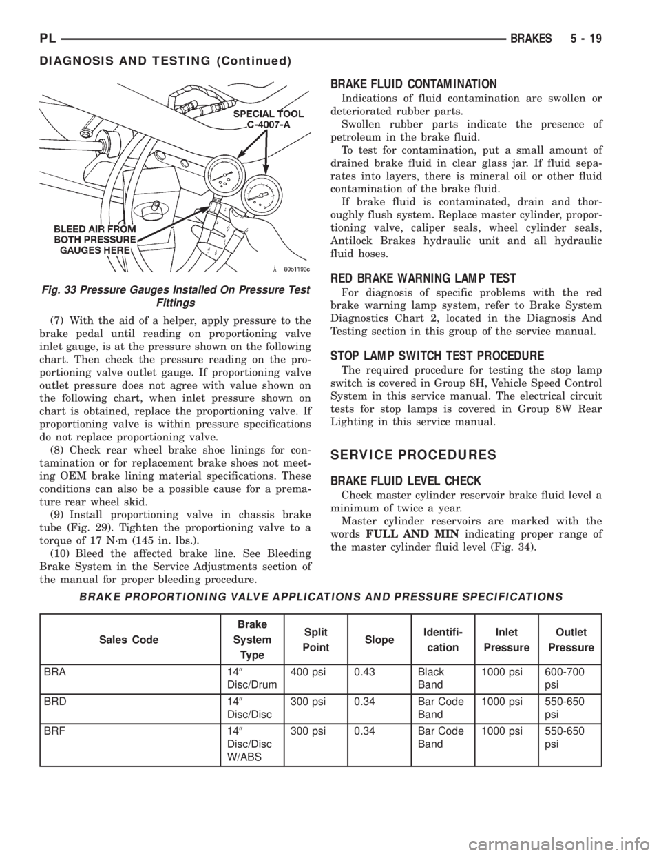
(7) With the aid of a helper, apply pressure to the
brake pedal until reading on proportioning valve
inlet gauge, is at the pressure shown on the following
chart. Then check the pressure reading on the pro-
portioning valve outlet gauge. If proportioning valve
outlet pressure does not agree with value shown on
the following chart, when inlet pressure shown on
chart is obtained, replace the proportioning valve. If
proportioning valve is within pressure specifications
do not replace proportioning valve.
(8) Check rear wheel brake shoe linings for con-
tamination or for replacement brake shoes not meet-
ing OEM brake lining material specifications. These
conditions can also be a possible cause for a prema-
ture rear wheel skid.
(9) Install proportioning valve in chassis brake
tube (Fig. 29). Tighten the proportioning valve to a
torque of 17 N´m (145 in. lbs.).
(10) Bleed the affected brake line. See Bleeding
Brake System in the Service Adjustments section of
the manual for proper bleeding procedure.
BRAKE FLUID CONTAMINATION
Indications of fluid contamination are swollen or
deteriorated rubber parts.
Swollen rubber parts indicate the presence of
petroleum in the brake fluid.
To test for contamination, put a small amount of
drained brake fluid in clear glass jar. If fluid sepa-
rates into layers, there is mineral oil or other fluid
contamination of the brake fluid.
If brake fluid is contaminated, drain and thor-
oughly flush system. Replace master cylinder, propor-
tioning valve, caliper seals, wheel cylinder seals,
Antilock Brakes hydraulic unit and all hydraulic
fluid hoses.
RED BRAKE WARNING LAMP TEST
For diagnosis of specific problems with the red
brake warning lamp system, refer to Brake System
Diagnostics Chart 2, located in the Diagnosis And
Testing section in this group of the service manual.
STOP LAMP SWITCH TEST PROCEDURE
The required procedure for testing the stop lamp
switch is covered in Group 8H, Vehicle Speed Control
System in this service manual. The electrical circuit
tests for stop lamps is covered in Group 8W Rear
Lighting in this service manual.
SERVICE PROCEDURES
BRAKE FLUID LEVEL CHECK
Check master cylinder reservoir brake fluid level a
minimum of twice a year.
Master cylinder reservoirs are marked with the
wordsFULL AND MINindicating proper range of
the master cylinder fluid level (Fig. 34).
Fig. 33 Pressure Gauges Installed On Pressure Test
Fittings
BRAKE PROPORTIONING VALVE APPLICATIONS AND PRESSURE SPECIFICATIONS
Sales CodeBrake
System
TypeSplit
PointSlopeIdentifi-
cationInlet
PressureOutlet
Pressure
BRA 149
Disc/Drum400 psi 0.43 Black
Band1000 psi 600-700
psi
BRD 149
Disc/Disc300 psi 0.34 Bar Code
Band1000 psi 550-650
psi
BRF 149
Disc/Disc
W/ABS300 psi 0.34 Bar Code
Band1000 psi 550-650
psi
PLBRAKES 5 - 19
DIAGNOSIS AND TESTING (Continued)