1999 DODGE NEON refrigerant type
[x] Cancel search: refrigerant typePage 905 of 1200
BINDING STICKING SEIZED
SHAKE SHUDDER VIBRATION
CONDITION POSSIBLE CAUSES CORRECTION
CATCHES, STICKS IN CERTAIN
POSITIONS OR IS DIFFICULT TO
TURN.1. Low power steering fluid level. 1. Fill power steering fluid reservoir
to specified level and perform
leakage diagnosis.
2. Tires not inflated to specified
pressure.2. Inflate tires to the specified
pressure.
3. Lack of lubrication in front
suspension control arm ball joints.3. Lubricate ball joints if ball joints
are not a lubricated for life type ball
joint. If ball joint is a lubricated for
life ball joint, replace ball joint or
control arm.
4. Lack of lubrication in front
suspension outer tie rod ends.4. Lubricate tie rod ends if they are
not a lubricated for life type. If tie rod
end is a lubricated for life type,
replace tie rod end.
5. Loose power steering pump drive
belt.5. Tighten the power steering pump
drive belt to the specified tension.
See accessory drive in service
manual.
6. Faulty power steering pump flow
control. (Verify cause using Power
Steering Pump Test Procedure.)6. Replace power steering pump.
7. Excessive friction in steering
column or intermediate shaft.7. Correct condition. (See Steering
Column Service Procedure)
8. Steering column coupler binding. 8. Realign the steering column to
eliminate the binding condition.
9. Binding upper strut bearing. 9. Correct binding condition in strut
bearing.
10 Excessive friction in steering
gear.10 Replace steering gear assembly.
CONDITION POSSIBLE CAUSES CORRECTION
VIBRATION OF THE STEERING
WHEEL AND/OR DASH DURING
DRY PARK OR LOW SPEED
STEERING MANEUVERS.1. Air in the fluid of the power
steering system.1. Steering shudder can be expected
in new vehicles and vehicles with
recent steering system repairs.
Shudder should improve after the
vehicle has been driven several
weeks.
2. Tires not properly inflated. 2. Inflate tires to the specified
pressure.
3. Excessive engine vibration. 3. Ensure that the engine is running
properly.
4. Loose tie rod end. 4. Check that the inner to outer tie
rod jam nut for is tight. If required,
tighten the jam nut to the specified
torque.
5.Overcharged air conditioning
system.5.Check air conditioning pump head
pressure. (See Air Conditioning
Refrigerant System Diagnosis)
19 - 4 STEERINGPL
DIAGNOSIS AND TESTING (Continued)
Page 1135 of 1200
GENERAL INFORMATION
INTRODUCTION
Both the heater and the heater/air conditioning
systems share many of the same functioning compo-
nents. This group will deal with both systems
together when component function is common, and
separately when they are not.
For proper operation of the instrument panel con-
trols, refer to the Owner's Manual provided with the
vehicle.
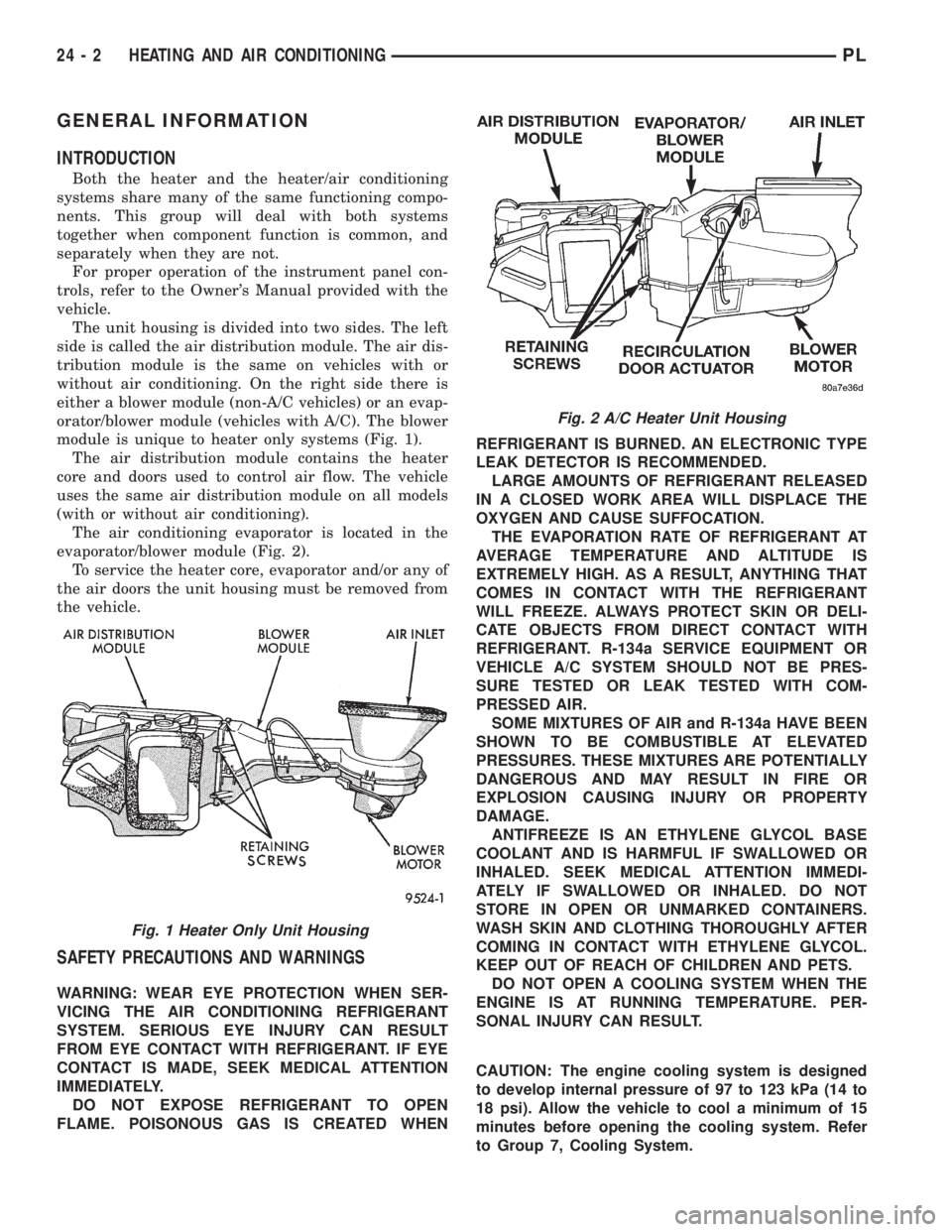
The unit housing is divided into two sides. The left
side is called the air distribution module. The air dis-
tribution module is the same on vehicles with or
without air conditioning. On the right side there is
either a blower module (non-A/C vehicles) or an evap-
orator/blower module (vehicles with A/C). The blower
module is unique to heater only systems (Fig. 1).
The air distribution module contains the heater
core and doors used to control air flow. The vehicle
uses the same air distribution module on all models
(with or without air conditioning).
The air conditioning evaporator is located in the
evaporator/blower module (Fig. 2).
To service the heater core, evaporator and/or any of
the air doors the unit housing must be removed from
the vehicle.
SAFETY PRECAUTIONS AND WARNINGS
WARNING: WEAR EYE PROTECTION WHEN SER-
VICING THE AIR CONDITIONING REFRIGERANT
SYSTEM. SERIOUS EYE INJURY CAN RESULT
FROM EYE CONTACT WITH REFRIGERANT. IF EYE
CONTACT IS MADE, SEEK MEDICAL ATTENTION
IMMEDIATELY.
DO NOT EXPOSE REFRIGERANT TO OPEN
FLAME. POISONOUS GAS IS CREATED WHENREFRIGERANT IS BURNED. AN ELECTRONIC TYPE
LEAK DETECTOR IS RECOMMENDED.
LARGE AMOUNTS OF REFRIGERANT RELEASED
IN A CLOSED WORK AREA WILL DISPLACE THE
OXYGEN AND CAUSE SUFFOCATION.
THE EVAPORATION RATE OF REFRIGERANT AT
AVERAGE TEMPERATURE AND ALTITUDE IS
EXTREMELY HIGH. AS A RESULT, ANYTHING THAT
COMES IN CONTACT WITH THE REFRIGERANT
WILL FREEZE. ALWAYS PROTECT SKIN OR DELI-
CATE OBJECTS FROM DIRECT CONTACT WITH
REFRIGERANT. R-134a SERVICE EQUIPMENT OR
VEHICLE A/C SYSTEM SHOULD NOT BE PRES-
SURE TESTED OR LEAK TESTED WITH COM-
PRESSED AIR.
SOME MIXTURES OF AIR and R-134a HAVE BEEN
SHOWN TO BE COMBUSTIBLE AT ELEVATED
PRESSURES. THESE MIXTURES ARE POTENTIALLY
DANGEROUS AND MAY RESULT IN FIRE OR
EXPLOSION CAUSING INJURY OR PROPERTY
DAMAGE.
ANTIFREEZE IS AN ETHYLENE GLYCOL BASE
COOLANT AND IS HARMFUL IF SWALLOWED OR
INHALED. SEEK MEDICAL ATTENTION IMMEDI-
ATELY IF SWALLOWED OR INHALED. DO NOT
STORE IN OPEN OR UNMARKED CONTAINERS.
WASH SKIN AND CLOTHING THOROUGHLY AFTER
COMING IN CONTACT WITH ETHYLENE GLYCOL.
KEEP OUT OF REACH OF CHILDREN AND PETS.
DO NOT OPEN A COOLING SYSTEM WHEN THE
ENGINE IS AT RUNNING TEMPERATURE. PER-
SONAL INJURY CAN RESULT.
CAUTION: The engine cooling system is designed
to develop internal pressure of 97 to 123 kPa (14 to
18 psi). Allow the vehicle to cool a minimum of 15
minutes before opening the cooling system. Refer
to Group 7, Cooling System.
Fig. 2 A/C Heater Unit Housing
Fig. 1 Heater Only Unit Housing
24 - 2 HEATING AND AIR CONDITIONINGPL
Page 1139 of 1200
outlets in various combinations using the mode selec-
tor. There are 17 different mode selections possible.
Air flow velocity can be adjusted with the blower
speed selector switch on the instrument panel.
On A/C equipped vehicles the ambient air intake
can be controlled by opening and closing the recircu-
lating air door. When placed in RECIRC, air that is
inside vehicle is removed continuously and recircu-
lated through unit housing. Ambient air cannot be
controlled on vehicles without A/C. The system uses
outside air at all times.
The air conditioning compressor can be engaged by
turning the fan switch counterclockwise from the off
position. It can also be engaged by placing the mode
control in the defrost position. This will remove heat
and humidity from the air before it is directed
through or around the heater core.
SYSTEM OIL LEVEL
It is important to have the correct amount of oil in
the A/C system to ensure proper lubrication of the
compressor. Too little oil will result in damage to the
compressor. Too much oil will reduce the cooling
capacity of the system and consequently result in
higher discharge air temperatures.
NOTE: The oil used in the compressor is ND8 PAG
R-134a refrigerant oil. Only refrigerant oil of the
same type should be used to service the system.
Do not use any other oil. The oil container should
be kept tightly capped until it is ready for use.
Tightly cap afterwards to prevent contamination
from dirt and moisture. Refrigerant oil will quickly
absorb any moisture it comes in contact with. Spe-
cial effort must be used to keep all R-134a system
components moisture-free. Moisture in the oil is
very difficult to remove and will cause a reliability
problem with the compressor.
It will not be necessary to check oil level in the
compressor or to add oil unless there has been an oil
loss. Oil loss at a leak point will be evident by the
presence of a wet, shiny surface around the leak.
REFRIGERANT OIL LEVEL CHECK
When an air conditioning system is first assem-
bled, all components (except the compressor) are
refrigerant oil free. After the system has been
charged with R-134a refrigerant and operated, the oil
in the compressor is dispersed through the lines and
components. The evaporator, condenser, and filter-
drier will retain a significant amount of oil, refer to
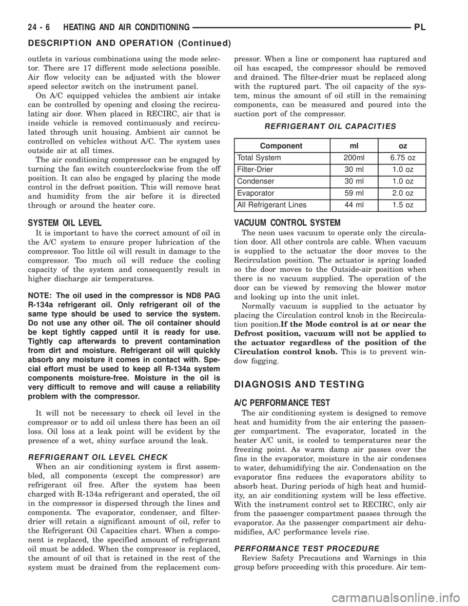
the Refrigerant Oil Capacities chart. When a compo-
nent is replaced, the specified amount of refrigerant
oil must be added. When the compressor is replaced,
the amount of oil that is retained in the rest of the
system must be drained from the replacement com-pressor. When a line or component has ruptured and
oil has escaped, the compressor should be removed
and drained. The filter-drier must be replaced along
with the ruptured part. The oil capacity of the sys-
tem, minus the amount of oil still in the remaining
components, can be measured and poured into the
suction port of the compressor.
VACUUM CONTROL SYSTEM
The neon uses vacuum to operate only the circula-
tion door. All other controls are cable. When vacuum
is supplied to the actuator the door moves to the
Recirculation position. The actuator is spring loaded
so the door moves to the Outside-air position when
there is no vacuum supplied. The operation of the
door can be viewed by removing the blower motor
and looking up into the unit inlet.
Normally vacuum is supplied to the actuator by
placing the Circulation control knob in the Recircula-
tion position.If the Mode control is at or near the
Defrost position, vacuum will not be applied to
the actuator regardless of the position of the
Circulation control knob.This is to prevent win-
dow fogging.
DIAGNOSIS AND TESTING
A/C PERFORMANCE TEST
The air conditioning system is designed to remove
heat and humidity from the air entering the passen-
ger compartment. The evaporator, located in the
heater A/C unit, is cooled to temperatures near the
freezing point. As warm damp air passes over the
fins in the evaporator, moisture in the air condenses
to water, dehumidifying the air. Condensation on the
evaporator fins reduces the evaporators ability to
absorb heat. During periods of high heat and humid-
ity, an air conditioning system will be less effective.
With the instrument control set to RECIRC, only air
from the passenger compartment passes through the
evaporator. As the passenger compartment air dehu-
midifies, A/C performance levels rise.
PERFORMANCE TEST PROCEDURE
Review Safety Precautions and Warnings in this
group before proceeding with this procedure. Air tem-
REFRIGERANT OIL CAPACITIES
Component ml oz
Total System 200ml 6.75 oz
Filter-Drier 30 ml 1.0 oz
Condenser 30 ml 1.0 oz
Evaporator 59 ml 2.0 oz
All Refrigerant Lines 44 ml 1.5 oz
24 - 6 HEATING AND AIR CONDITIONINGPL
DESCRIPTION AND OPERATION (Continued)
Page 1149 of 1200
the refrigerant system likely has a leak that must be
corrected. If the refrigerant system maintains speci-
fied vacuum for at least 30 minutes, start the vac-
uum pump, open the suction and discharge valves.
Then allow the system to evacuate an additional 10
minutes.
(3) Close all valves. Turn off and disconnect the
vacuum pump.
(4) The refrigerant system is prepared to be
charged with refrigerant.
R-134a REFRIGERANT
This vehicle uses a new type of refrigerant called
R-134a. It is a non-toxic, non-flammable, clear color-
less liquefied gas.
R-134a refrigerant is not compatible with R-12
refrigerant in an air conditioning system. Even a
small amount of R-12 in a R-134a system could cause
compressor failure, refrigerant oil to sludge and/or
poor performance.Never add any other type of
refrigerant to a system designed to use R-134a
refrigerant. System failure will occur.
The high pressure service port is located on the
ffilter/drier. The low pressure service port is located
on the suction line near the strut tower.
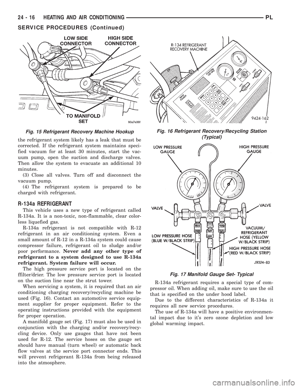
When servicing a system, it is required that an air
conditioning charging recovery/recycling machine be
used (Fig. 16). Contact an automotive service equip-
ment supplier for proper equipment. Refer to the
operating instructions provided with the equipment
for proper operation.
A manifold gauge set (Fig. 17) must also be used in
conjunction with the charging and/or recovery/recy-
cling device. Only use gauges that have not been
used for R-12. The service hoses on the gauge set
should have manual (turn wheel) or automatic back
flow valves at the service port connector ends. This
will prevent refrigerant R-134a from being released
into the atmosphere.R-134a refrigerant requires a special type of com-
pressor oil. When adding oil, make sure to use the oil
that is specified on the under hood label.
Due to the different characteristics of R-134a it
requires all new service procedures.
The use of R-134a will have a positive environmen-
tal impact due to it's zero ozone depletion and low
global warming impact.
Fig. 15 Refrigerant Recovery Machine HookupFig. 16 Refrigerant Recovery/Recycling Station
(Typical)
Fig. 17 Manifold Gauge Set- Typical
24 - 16 HEATING AND AIR CONDITIONINGPL
SERVICE PROCEDURES (Continued)
Page 1150 of 1200
SERVICING REFRIGERANT OIL LEVEL
CAUTION: The refrigerant oil used in a R-134a A/C
system is unique. Use only oils which were
designed to work with R-134a refrigerant. The oil
designated for this vehicle is ND8 PAG (polyalka-
lene glycol).
Recovery/recycling equipment will measure the
lubricant being removed. This is the amount of lubri-
cant to be added back to the system. If a new com-
pressor is being installed, drain lubricant from old
compressor, measure the amount drained and discard
old lubricant. Drain the lubricant from the new com-
pressor into a clean container. Return the amount of
lubricant measured from the old compressor, plus the
amount reclaimed from the system back into the new
compressor.
(1) Discharge refrigerant system using recovery/re-
cycling equipment if charge is present.
(2) Disconnect refrigerant lines from A/C compres-
sor. Cap the open lines to prevent moisture from
entering system.
(3) Remove compressor from vehicle.
(4) From suction port on top of compressor, drain
lubricant from compressor.
(5) Add system capacity minus the capacity of
components that have not been replaced. Refer to the
Lubricant Capacity Chart. Add lubricant through the
suction port on compressor. This is not to exceed 200
ml (6.75 oz.) in total.
(6) Install compressor and connect refrigerant
lines. Then evacuate and charge refrigerant system.
SYSTEM LEAK CHECKING
WARNING: R-134a SERVICE EQUIPMENT OR VEHI-
CLE A/C SYSTEM SHOULD NOT BE PRESSURE
TESTED OR LEAK TESTED WITH COMPRESSED
AIR. MIXTURE OF AIR and R-134a CAN BE COM-
BUSTIBLE AT ELEVATED PRESSURES. THESE MIX-
TURES ARE POTENTIALLY DANGEROUS AND MAY
RESULT IN FIRE OR EXPLOSION CAUSING INJURY
OR PROPERTY DAMAGE.
AVOID BREATHING A/C REFRIGERANT AND
LUBRICANT VAPOR OR MIST. EXPOSURE MAY
IRRITATE EYES, NOSE AND THROAT. USE ONLY
APPROVED SERVICE EQUIPMENT MEETING SAE
REQUIREMENTS TO DISCHARGE R-134a SYSTEM.
IF ACCIDENTAL SYSTEM DISCHARGE OCCURS,
VENTILATE WORK AREA BEFORE RESUMING SER-
VICE.
If the A/C system is not cooling properly, determine
if the refrigerant system is fully charged with
R-134a. This is accomplished by performing a system
Charge Level-Check or Fill. If while performing thistest A/C liquid line pressure is less than 345 kPa (50
psi) proceed to Empty Refrigerant System Leak Test.
If liquid line pressure is greater than 345 kPa (50
psi) proceed to low refrigerant level leak test. If the
refrigerant system is empty or low in refrigerant
charge, a leak at any line fitting or component seal is
likely. A review of the fittings, lines and components
for oily residue is an indication of the leak location.
To detect a leak in the refrigerant system, perform
one of the following procedures as indicated by the
symptoms.
EMPTY REFRIGERANT SYSTEM LEAK TEST
(1) Evacuate the refrigerant system to the lowest
degree of vacuum possible (approx. 28 in Hg.). Deter-
mine if the system holds a vacuum for 15 minutes. If
vacuum is held, a leak is probably not present. If sys-
tem will not maintain vacuum level, proceed with
this procedure.
(2) Prepare a .284 Kg. (10 oz.) refrigerant charge
to be injected into the system.
(3) Connect and dispense .284 Kg. (10 oz.) of
refrigerant into the evacuated refrigerant system.
(4) Proceed to Step 2 of Low Refrigerant Level
Leak Test.
LOW REFRIGERANT LEVEL LEAK TEST
(1) Determine if there is any (R-134a) refrigerant
in the system.
(2) Position the vehicle in a wind free work area.
This will aid in detecting small leaks.
(3) Bring the refrigerant system up to operating
temperature and pressure. This is done by allowing
the engine to run for five minutes with the system
set to the following:
²Transaxle in Park
²Engine Idling at 700 rpm
²A/C Controls Set in 100 percent outside air
²Blower switch in the high A/C position
²A/C in the ON position
²Open all windows
CAUTION: A leak detector designed for R-12 refrig-
erant (only) will not detect leaks in a R-134a refrig-
erant system.
(4) Shut off the vehicle and wait 2 to 7 minutes.
Then use an Electronic Leak Detector that is
designed to detect R-134a type refrigerant and search
for leaks. Fittings, lines, or components that appear
to be oily usually indicates a refrigerant leak. To
inspect the evaporator core for leaks, insert the leak
detector probe into the drain tube opening or a heat
duct. A R-134a dye is available to aid in leak detec-
tion, use only Chrysler approved refrigerant dye.
PLHEATING AND AIR CONDITIONING 24 - 17
SERVICE PROCEDURES (Continued)
Page 1152 of 1200
(4) Remove two resistor block retaining screws.
The screw threads attaching the resistor block are
not full length. It is necessary to gently pry out the
resistor block while turning the screws counterclock-
wise enabling the threads to engages.
(5) Remove resistor block from vehicle.
INSTALLATION
For installation, reverse the above procedures.
BLOWER MOTOR WHEEL
The blower motor wheel is only serviced with the
blower motor. The wheel and the motor are balanced
as an assembly. If the blower motor wheel requires
replacement, the blower motor must also be replaced.
Refer to blower motor for replacement procedure.
COMPRESSOR
CAUTION: Add only new lubricant when system
requires additional lubricant. Do not use old
reclaimed lubricant.
REMOVAL
The A/C compressor may be unbolted and reposi-
tioned without discharging the refrigerant system.
Discharging is not necessary if removing the com-
pressor clutch/coil assembly, engine, cylinder head, or
alternator.
WARNING: REFRIGERANT PRESSURES REMAIN
HIGH EVEN THOUGH THE ENGINE MAY BE
TURNED OFF. DO NOT TWIST OR KINK THE
REFRIGERANT LINES WHEN REMOVING A FULLY
CHARGED COMPRESSOR. SAFETY GLASSES
MUST BE WORN.
(1) Disconnect battery negative cable.
(2) Loosen and remove drive belts, refer to Group
7, Engine Cooling.
(3) Using a R-134a refrigerant recovery machine,
remove the refrigerant from A/C system. If the com-
pressor is being replaced.
(4) Disconnect compressor clutch wire lead.
(5) Remove refrigerant lines from compressor, if
necessary.
(6) If system is left open place plug/cap over open
lines.
(7) Remove compressor attaching bolt.
(8) Remove compressor. If refrigerant lines were
not removed, lift compressor/clutch assembly and tie
it to a suitable component.
INSTALLATION
For installation, reverse the above procedures.
COMPRESSOR CLUTCH/COIL ASSEMBLY
Compressor assembly must be removed from mount-
ing. Although, refrigerant discharge is not necessary.
REMOVAL
(1) Remove the compressor shaft bolt (Fig. 20). A
band type oil filter removal tool can be placed around
the clutch plate to aid in bolt removal.
(2) Tap the clutch plate with a plastic hammer and
remove clutch plate and shim(s) (Fig. 21).
NOTE: Use care not to lose any of the shim(s).
CAUTION: Do not use screwdrivers between the
clutch plate assembly and pulley to remove front
plate as this may damage the front plate assembly.
Fig. 20 Compressor Shaft Bolt and Clutch Plate
Fig. 21 Clutch Plate and Shim(s)
PLHEATING AND AIR CONDITIONING 24 - 19
REMOVAL AND INSTALLATION (Continued)
Page 1156 of 1200
(2) If previous probe was removed from top hole,
use a small plastic stick and make a new hole. Make
the hole 1/4 inch above or below the original hole in
the evaporator core.
(3) Insert new probe into hole between evaporator
fins.
(4) Reinstall rubber grommet into evaporator
probe access hole.
EXPANSION VALVE
WARNING: THE REFRIGERATION SYSTEM MUST
BE COMPLETELY EMPTY BEFORE PROCEEDING
WITH THIS OPERATION.
REMOVAL
(1) Remove the boot-type wire connector from the
pressure cut-off switch.
(2) Remove the center bolt of refrigerant line
plumbing sealing plate (Fig. 31).
(3) Carefully pull the refrigerant line-sealing plate
assembly from the expansion valve towards front of
vehicle. Do not scratch the expansion valve sealing
surfaces with pilot tubes.
(4) Cover the openings on A/C line-sealing plate
assembly to prevent contamination.
(5) Remove two screws securing the expansion
valve to the evaporator sealing plate.
(6) Carefully remove valve.
INSTALLATION
(1) Remove and replace the aluminum gasket on
the evaporator sealing plate.
(2) Carefully hold the expansion valve to the evap-
orator sealing plate so not to scratch the sealing sur-
face. Install two screws and tighten to 1163 N´m
(100630 in. lbs.).
(3) Remove and replace the aluminum gasket on
the refrigerant line- sealing plate assembly.(4) Carefully hold the refrigerant line-sealing plate
assembly to the expansion valve. Install bolt and
tighten to 2363 N´m (200630 in. lbs.).
(5) Connect wires to low pressure cut-off switch.
(6) Evacuate and recharge system.
(7) After expansion valve is installed, system is
charged, and leaks have been checked, repeat A/C
performance check.
A/C FILTER/DRIER
The filter/drier is mounted in a rubber grommet on
the right side of the engine compartment. The refrig-
erant must be recovered from the A/C system before
replacing the filter/drier assembly.
WARNING: THE REFRIGERATION SYSTEM MUST
BE COMPLETELY RECOVERED BEFORE PRO-
CEEDING WITH THIS OPERATION.
REMOVAL
(1) Disconnect liquid line from filter/drier.
(2) Disconnect liquid line on suction line assembly
from filter/drier.
(3) Pull filter/drier out of rubber grommet.
INSTALLATION
For installation, reverse the above procedures.
HIGH PRESSURE CUT OUT SWITCH
WARNING: THE REFRIGERANT MUST BE
REMOVED FROM THE SYSTEM BEFORE REMOV-
ING THE HIGH PRESSURE CUT OUT SWITCH.
REMOVAL
(1) Disconnect wiring connector at the switch (Fig.
32).
(2) Remove internal snap ring.
Fig. 30 Evaporator Probe LocationFig. 31 Expansion Valve
PLHEATING AND AIR CONDITIONING 24 - 23
REMOVAL AND INSTALLATION (Continued)