1999 DODGE NEON check transmission fluid
[x] Cancel search: check transmission fluidPage 4 of 1200
MAINTENANCE SCHEDULES
INDEX
page page
GENERAL INFORMATION
INTRODUCTION......................... 3
SCHEDULE ± A.......................... 3SCHEDULE ± B.......................... 4
UNSCHEDULED INSPECTION............... 3
GENERAL INFORMATION
INTRODUCTION
Service and maintenance procedures for compo-
nents and systems listed in Schedule ± A or B can be
found by using the Group Tab Locator index at the
front of this manual. If it is not clear which group
contains the information needed, refer to the index at
the back of this manual.
There are two maintenance schedules that show
proper service based on the conditions that the vehi-
cle is subjected to. Use the schedule that best
describes these conditions.
Schedule ±A, lists maintenance recommended for
vehicles used for general transportation.
Schedule ±B, lists maintenance recommended for
vehicles used under the following conditions:
²Frequent short trip driving less than 5 miles (8
km)
²Frequent driving in dusty conditions
²Frequent trailer towing
²Extensive idling
²More than 50% of your driving is at sustained
high speeds during hot weather, above 90ÉF (32ÉC)
Where time and mileage are listed, follow the
interval that occurs first.
EMISSION CONTROL SYSTEM MAINTENANCE
The scheduled emission maintenance listed inbold
typeon the Maintenance Schedules, must be done at
the mileage specified to assure the continued proper
functioning of the emission control system. These,
and all other maintenance services included in this
manual, should be done to provide the best vehicle
performance and reliability. More frequent mainte-
nance may be needed for vehicles in severe operating
conditions such as dusty areas and very short trip
driving.
UNSCHEDULED INSPECTION
At Each Stop For Fuel
²Check engine oil level, add as required.
²Check windshield washer solvent and add if
required.
Once A Month
²Check tire pressure and look for unusual wear
or damage.
²Inspect battery, clean, and tighten terminals as
required.
²Check fluid levels of coolant reservoir, power
steering and automatic transmission and add as
required.
²Check all lights and all other electrical items for
correct operation.
At Each Oil Change
²Inspect exhaust system.
²Inspect brake hoses.
²Inspect the CV joints and front suspension com-
ponents.
²Rotate the tires at each oil change interval
shown on Schedule ± A (7,500 miles) or every other
interval shown on schedule ± B (6,000 miles).
²Check coolant level, hoses and clamps.
²Check the manual transaxle fluid level.
²If the mileage is less than 7,500 miles (12 000
km) yearly, replace the engine oil filter at each oil
change.
SCHEDULE ± A
7,500 Miles (12 000 km) or at 6 months
²Change engine oil.
15,000 Miles (24 000 km) or at 12 months
²Change engine oil.
²Replace engine oil filter.
²Adjust drive belt tension.
22,500 Miles (36 000 km) or at 18 months
²Change engine oil.
²Inspect the front brake pads and rear brake lin-
ings.
30,000 Miles (48 000 km) or at 24 months
²Change engine oil.
²Replace engine oil filter.
²Lubricate front suspension ball joints.
²Adjust drive belt tension.
PLLUBRICATION AND MAINTENANCE 0 - 3
Page 5 of 1200

²Replace air cleaner element.
²Replace spark plugs.
²Change automatic transmission fluid.
37,500 Miles (60 000 km) or at 30 months
²Change engine oil.
45,000 Miles (72 000 km) or at 36 months
²Change engine oil.
²Replace engine oil filter.
²Inspect front brake pads and rear brake linings.
²Adjust drive belt tension.
²Flush and replace engine coolant at 36 months,
regardless of mileage.
52,500 Miles (84 000 km) or at 42 months
²Change engine oil.
²Flush and replace engine coolant if not done at
36 months.
60,000 Miles (96 000 km) or at 48 months
²Change engine oil.
²Replace engine oil filter.
²Check and replace, if necessary***, the PCV
valve.**
²Lubricate front suspension upper ball joints.
²Replace drive belts.
²Replace air cleaner element.
²Replace ignition cables.
²Replace spark plugs.
²Change automatic transmission fluid.
67,500 Miles (108 000 km) or at 54 months
²Change engine oil.
²Inspect front brake pads and rear brake linings.
75,000 Miles (120 000 km) or at 60 months
²Change engine oil.
²Replace engine oil filter.
²Adjust drive belt tension.
²Flush and replace engine coolant if it has been
30,000 miles (48 000 km) or 24 months since last
change.
82,500 Miles (132 000 km) or at 66 months
²Change engine oil.
²Flush and replace engine coolant if it has been
30,000 miles (48 000 km) or 24 months since last
change.
90,000 Miles (144 000 km) or at 72 months
²Change engine oil.
²Replace engine oil filter.
²Check and replace, if necessary***, the PCV
valve.**
²Lubricate front suspension upper ball joints.
²Inspect front brake pads and rear brake linings.²Adjust drive belt tension.
²Replace air cleaner air cleaner element.
²Replace spark plugs.
²Change automatic transmission fluid.
97,500 Miles (156 000 km) or at 78 months
²Change engine oil.
105,000 Miles (168 000 km)
²Change engine oil.
²Replace engine oil filter.
²Replace engine timing belt
²Adjust drive belt tension.
SCHEDULE ± B
NOTE: * Follow this schedule if you usually operate
your vehicle under one or more of the following
conditions. Change the automatic transmission
fluid and filter every 15,000 miles (24 000 km) if you
usually operate your vehicle under one of the con-
ditions marked with an *.
3,000 Miles (5 000 km)
²Change engine oil
6,000 Miles (10 000 km)
²Change engine oil
²Replace engine oil filter.
9,000 Miles (14 000 km)
²Change engine oil
²Inspect front brake pads and rear brake lining.
12,000 Miles (19 000 km)
²Change engine oil
²Replace engine oil filter.
15,000 Miles (24 000 km)
²Change engine oil
²Adjust drive belt tension.
²Inspect and replace, if required, the air
cleaner element.
²Change automatic transaxle fluid and filter.
Adjust the bands.*
18,000 Miles (29 000 km)
²Change engine oil
²Replace engine oil filter.
²Inspect front brake pads and rear brake linings.
21,000 Miles (34 000 km)
²Change engine oil
0 - 4 LUBRICATION AND MAINTENANCEPL
GENERAL INFORMATION (Continued)
Page 6 of 1200

24,000 Miles (38 000 km)
²Change engine oil
²Replace engine oil filter.
27,000 Miles (43 000 km)
²Change engine oil
²Inspect front brake pads and rear brake linings.
30,000 Miles (48 000 km)
²Change engine oil
²Replace engine oil filter.
²Check and replace, if necessary, the PCV
valve.**
²Lubricate front suspension upper ball joints.
²Adjust drive belt tension.
²Replace air cleaner element.
²Replace spark plugs.
²Change automatic transmission fluid and filter.
Adjust the bands.*
33,000 Miles (53 000 km)
²Change engine oil.
36,000 Miles (58 000 km)
²Change engine oil.
²Replace engine oil filter.
²Flush and replace engine coolant.
²Inspect front brake pads and rear brake linings.
39,000 Miles (62 000 km)
²Change engine oil.
42,000 Miles (67 000 km)
²Change engine oil.
²Replace engine oil filter.
45,000 Miles (72 000 km)
²Change engine oil.
²Inspect front brake pads and rear brake linings.
²Inspect and replace, if necessary, the air
cleaner element.
²Adjust drive belt tension.
²Change automatic transaxle fluid and filter.
Adjust the bands.*
48,000 Miles (77 000 km)
²Change engine oil.
²Replace engine oil filter.
51,000 Miles (82 000 km)
²Change engine oil.
²Flush and replace engine coolant.
54,000 Miles (86 000 km)
²Change engine oil.
²Replace engine oil filter.
²Inspect front brake pads and rear brake linings.
57,000 Miles (91 000 km)
²Change engine oil.
60,000 Miles (96 000 km)
²Change engine oil.
²Replace engine oil filter.
²Check and replace, if necessary***, the PCV
valve.**
²Lubricate front suspension upper ball joints.
²Replace drive belts.
²Replace air cleaner element.
²Replace ignition cables.
²Replace spark plugs.
²Change automatic transaxle fluid and filter.
Adjust the bands.*
63,000 Miles (101 000 km)
²Change engine oil.
²Inspect front brake pads and rear brake linings.
66,000 Miles (106 000 km)
²Change engine oil.
²Replace engine oil filter.
69,000 Miles (110 000 km)
²Change engine oil.
72,000 Miles (115 000 km)
²Change engine oil.
²Replace engine oil filter.
²Inspect front brake pads and rear brake linings.
75,000 Miles (120 000 km)
²Change engine oil.
²Adjust drive belt tension.
²Inspect and replace, if necessary, the air
cleaner element.
²Change automatic transaxle fluid and filter.
Adjust the bands.*
78,000 Miles (125 000 km)
²Change engine oil.
²Replace engine oil filter.
81,000 Miles (130 000 km)
²Change engine oil.
²Flush and replace the engine coolant.
²Inspect front brake pads and rear brake linings.
84,000 Miles (134 000 km)
²Change engine oil.
²Replace engine oil filter.
87,000 Miles (139 000 km)
²Change engine oil.
PLLUBRICATION AND MAINTENANCE 0 - 5
GENERAL INFORMATION (Continued)
Page 213 of 1200
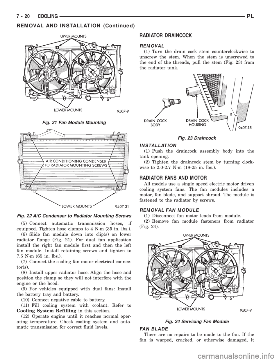
(5) Connect automatic transmission hoses, if
equipped. Tighten hose clamps to 4 N´m (35 in. lbs.).
(6) Slide fan module down into clip(s) on lower
radiator flange (Fig. 21). For dual fan application
install the right fan module first and then the left
fan module. Install retaining screws and tighten to
7.5 N´m (65 in. lbs.).
(7) Connect the cooling fan motor electrical connec-
tor(s).
(8) Install upper radiator hose. Align the hose and
position the clamp so they will not interfere with the
engine or the hood.
(9) For vehicles equipped with dual fans: Install
the battery tray and battery.
(10) Connect negative cable to battery.
(11) Fill cooling system with coolant. Refer to
Cooling System Refillingin this section.
(12) Operate engine until it reaches normal oper-
ating temperature. Check cooling system and auto-
matic transmission for correct fluid levels.
RADIATOR DRAINCOCK
REMOVAL
(1) Turn the drain cock stem counterclockwise to
unscrew the stem. When the stem is unscrewed to
the end of the threads, pull the stem (Fig. 23) from
the radiator tank.
INSTALLATION
(1) Push the draincock assembly body into the
tank opening.
(2) Tighten the draincock stem by turning clock-
wise to 2.0-2.7 N´m (18-25 in. lbs.).
RADIATOR FANS AND MOTOR
All models use a single speed electric motor driven
cooling system fans. The fan modules includes a
motor, fan blade, and support shroud. The module is
fastened to the radiator by screws.
REMOVAL FAN MODULE
(1) Disconnect fan motor leads from module.
(2) Remove fan module fasteners from radiator
(Fig. 24).
FAN BLADE
There are no repairs to be made to the fan. If the
fan is warped, cracked, or otherwise damaged, it
Fig. 21 Fan Module Mounting
Fig. 22 A/C Condenser to Radiator Mounting Screws
Fig. 23 Draincock
Fig. 24 Servicing Fan Module
7 - 20 COOLINGPL
REMOVAL AND INSTALLATION (Continued)
Page 912 of 1200
should be in the range of 345-552 kPa (50-80 psi).
The flow meter should read between 1.3 and 1.4
GPM
CAUTION: The following test procedure involves
testing power steering pump maximum pressure
output and flow control valve operation. Do not
leave valve closed for more than 5 seconds as the
pump could be damaged.
(8) Close valve fully three times and record high-
est pressure indicated each time.All three read-
ings must be above specifications and within
345 kPa (50 psi) of each other.
NOTE: Power steering pump maximum relief pres-
sure is 8240 to 8920 kPa (1195 to 1293 psi.).
²If power steering pump pressures above specifi-
cations but not within 345 kPa (50 psi) of each other,
then replace power steering pump.
²If pressures within 345 kPa (50 psi) of each
other but below specifications, then replace power
steering pump.
CAUTION: Do not force the pump to operate
against the stops for more than 5 seconds at a time
because, pump damage will result.
(9) Open test valve. Turn steering wheel to the
extreme left and right positions until against the
stops, recording the highest indicated pressure at
each position. Compare pressure gauge readings to
power steering pump specifications. If highest output
pressures are not the same against either stop, the
steering gear is leaking internally and must be
replaced.
SERVICE PROCEDURES
POWER STEERING SYSTEM FLUID LEVEL CHECK
WARNING: FLUID LEVEL SHOULD BE CHECKED
WITH ENGINE OFF TO PREVENT INJURY FROM
MOVING PARTS. DO NOT USE AUTOMATIC TRANS-
MISSION FLUID IN THE POWER STEERING SYS-
TEM. DO NOT OVERFILL THE POWER STEERING
SYSTEM.
Wipe reservoir filler cap free of dirt. Then check
fluid level. The dipstick should indicate COLD when
fluid is at normal ambient temperature, approxi-
mately 21ÉC to 27ÉC (70ÉF to 80ÉF). In all pumps add
fluid as necessary, use onlyMopar Power Steering
Fluid, or equivalent. DO NOT USE ANY TYPE
OF AUTOMATIC TRANSMISSION FLUID.
POWER STEERING PUMP INITIAL OPERATION
CAUTION: The fluid level should be checked with
engine off to prevent injury from moving compo-
nents. Use only MoparTPower Steering Fluid. Do
not use automatic transmission fluid. Do not over-
fill.
Wipe filler cap clean, then check the fluid level.
The dipstick should indicateFULL COLDwhen the
fluid is at normal temperature of approximately 21ÉC
to 27ÉC (70ÉF to 80ÉF).
(1) Fill the pump fluid reservoir to the proper level
and let the fluid settle for at least two (2) minutes.
(2) Start the engine and let run for a few seconds.
Then turn the engine off.
(3) Add fluid if necessary. Repeat the above proce-
dure until the fluid level remains constant after run-
ning the engine.
(4) Raise the front wheels off the ground.
(5) Start the engine. Slowly turn the steering
wheel right and left, lightly contacting the wheel
stops.
(6) Add power steering fluid if necessary.
(7) Lower the vehicle and turn the steering wheel
slowly from lock to lock.
(8) Stop the engine. Check the fluid level and refill
as required.
(9) If the fluid is extremely foamy, allow the vehi-
cle to stand a few minutes and repeat the above pro-
cedure.
POWER STEERING PUMP FLOW CONTROL VALVE
SEAL
The power steering pump does not require removal
from the engine for removal and replacement of the
flow control valve fitting O-Ring.
REMOVE
(1) Remove the power steering fluid pressure hose
from the power steering pump pressure fitting (Fig.
4).
(2) Remove the flow control valve fitting from the
power steering pump housing (Fig. 5).Prevent flow
control valve and spring from sliding out of
housing bore.
(3) Remove and discard O-ring seal from fitting.
INSTALL
(1) If necessary, clean and install flow control
valve and spring in pump housing bore.
(2) Install new O-ring seal on fitting.
(3) Install fitting in pump housing and tighten to
75 N´m (55 ft. lbs.)
(4) Install power steering fluid pressure hose on
flow control valve fitting.
PLSTEERING 19 - 11
DIAGNOSIS AND TESTING (Continued)
Page 914 of 1200
REMOVE
CAUTION: When removing and installing the
power steering pressure switch, the use of a 7/8
inch deep well socket is required. The deep well
socket will prevent damage to the plastic, electrical
connector area, of the power steering pressure
switch.
(1) Disconnect negative battery cable from the neg-
ative post of the battery. Be sure cable is isolated
from negative post on battery.
(2) Raise vehicle.
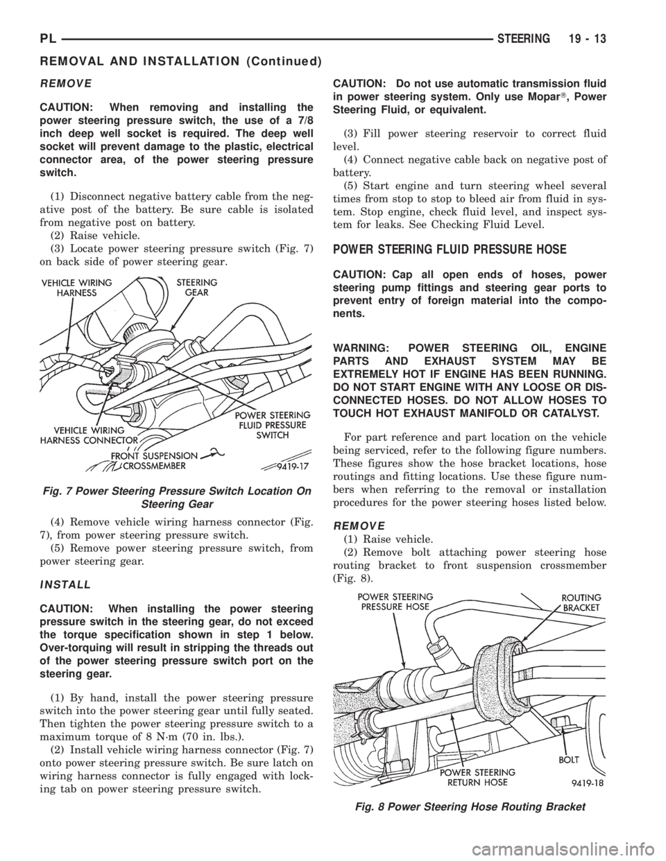
(3) Locate power steering pressure switch (Fig. 7)
on back side of power steering gear.
(4) Remove vehicle wiring harness connector (Fig.
7), from power steering pressure switch.
(5) Remove power steering pressure switch, from
power steering gear.
INSTALL
CAUTION: When installing the power steering
pressure switch in the steering gear, do not exceed
the torque specification shown in step 1 below.
Over-torquing will result in stripping the threads out
of the power steering pressure switch port on the
steering gear.
(1) By hand, install the power steering pressure
switch into the power steering gear until fully seated.
Then tighten the power steering pressure switch to a
maximum torque of 8 N´m (70 in. lbs.).
(2) Install vehicle wiring harness connector (Fig. 7)
onto power steering pressure switch. Be sure latch on
wiring harness connector is fully engaged with lock-
ing tab on power steering pressure switch.CAUTION: Do not use automatic transmission fluid
in power steering system. Only use MoparT, Power
Steering Fluid, or equivalent.
(3) Fill power steering reservoir to correct fluid
level.
(4) Connect negative cable back on negative post of
battery.
(5) Start engine and turn steering wheel several
times from stop to stop to bleed air from fluid in sys-
tem. Stop engine, check fluid level, and inspect sys-
tem for leaks. See Checking Fluid Level.
POWER STEERING FLUID PRESSURE HOSE
CAUTION: Cap all open ends of hoses, power
steering pump fittings and steering gear ports to
prevent entry of foreign material into the compo-
nents.
WARNING: POWER STEERING OIL, ENGINE
PARTS AND EXHAUST SYSTEM MAY BE
EXTREMELY HOT IF ENGINE HAS BEEN RUNNING.
DO NOT START ENGINE WITH ANY LOOSE OR DIS-
CONNECTED HOSES. DO NOT ALLOW HOSES TO
TOUCH HOT EXHAUST MANIFOLD OR CATALYST.
For part reference and part location on the vehicle
being serviced, refer to the following figure numbers.
These figures show the hose bracket locations, hose
routings and fitting locations. Use these figure num-
bers when referring to the removal or installation
procedures for the power steering hoses listed below.
REMOVE
(1) Raise vehicle.
(2) Remove bolt attaching power steering hose
routing bracket to front suspension crossmember
(Fig. 8).
Fig. 7 Power Steering Pressure Switch Location On
Steering Gear
Fig. 8 Power Steering Hose Routing Bracket
PLSTEERING 19 - 13
REMOVAL AND INSTALLATION (Continued)
Page 921 of 1200
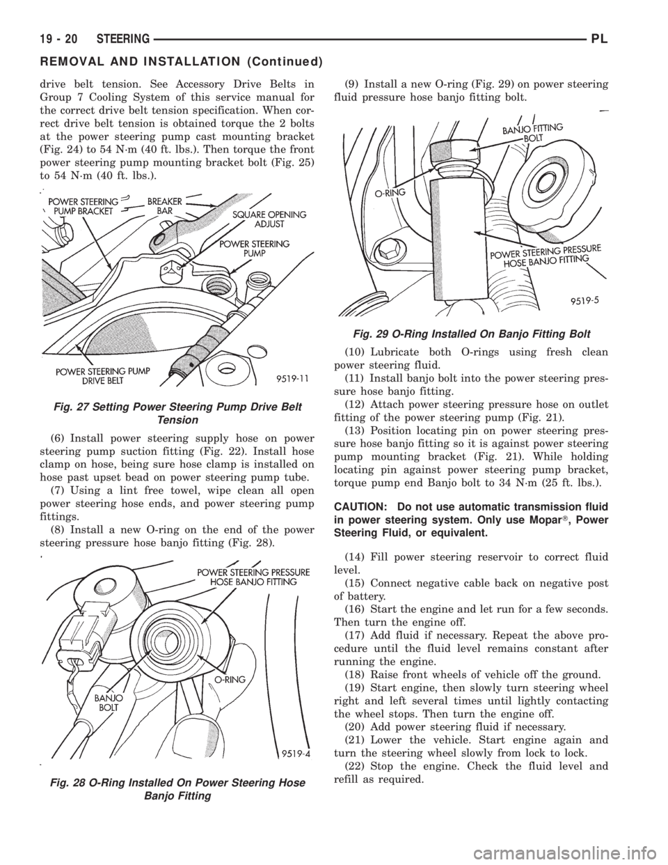
drive belt tension. See Accessory Drive Belts in
Group 7 Cooling System of this service manual for
the correct drive belt tension specification. When cor-
rect drive belt tension is obtained torque the 2 bolts
at the power steering pump cast mounting bracket
(Fig. 24) to 54 N´m (40 ft. lbs.). Then torque the front
power steering pump mounting bracket bolt (Fig. 25)
to 54 N´m (40 ft. lbs.).
(6) Install power steering supply hose on power
steering pump suction fitting (Fig. 22). Install hose
clamp on hose, being sure hose clamp is installed on
hose past upset bead on power steering pump tube.
(7) Using a lint free towel, wipe clean all open
power steering hose ends, and power steering pump
fittings.
(8) Install a new O-ring on the end of the power
steering pressure hose banjo fitting (Fig. 28).(9) Install a new O-ring (Fig. 29) on power steering
fluid pressure hose banjo fitting bolt.
(10) Lubricate both O-rings using fresh clean
power steering fluid.
(11) Install banjo bolt into the power steering pres-
sure hose banjo fitting.
(12) Attach power steering pressure hose on outlet
fitting of the power steering pump (Fig. 21).
(13) Position locating pin on power steering pres-
sure hose banjo fitting so it is against power steering
pump mounting bracket (Fig. 21). While holding
locating pin against power steering pump bracket,
torque pump end Banjo bolt to 34 N´m (25 ft. lbs.).
CAUTION: Do not use automatic transmission fluid
in power steering system. Only use MoparT, Power
Steering Fluid, or equivalent.
(14) Fill power steering reservoir to correct fluid
level.
(15) Connect negative cable back on negative post
of battery.
(16) Start the engine and let run for a few seconds.
Then turn the engine off.
(17) Add fluid if necessary. Repeat the above pro-
cedure until the fluid level remains constant after
running the engine.
(18) Raise front wheels of vehicle off the ground.
(19) Start engine, then slowly turn steering wheel
right and left several times until lightly contacting
the wheel stops. Then turn the engine off.
(20) Add power steering fluid if necessary.
(21) Lower the vehicle. Start engine again and
turn the steering wheel slowly from lock to lock.
(22) Stop the engine. Check the fluid level and
refill as required.
Fig. 27 Setting Power Steering Pump Drive Belt
Tension
Fig. 28 O-Ring Installed On Power Steering Hose
Banjo Fitting
Fig. 29 O-Ring Installed On Banjo Fitting Bolt
19 - 20 STEERINGPL
REMOVAL AND INSTALLATION (Continued)
Page 983 of 1200
31TH AUTOMATIC TRANSAXLE
INDEX
page page
GENERAL INFORMATION
FLUID LEVEL AND CONDITION............. 41
GENERAL INFORMATION................. 40
SELECTION OF LUBRICANT............... 41
SPECIAL ADDITIVES..................... 41
DESCRIPTION AND OPERATION
AUTOMATIC TRANSMISSION SHIFTER/
IGNITION INTERLOCK.................. 42
CLUTCHES, BAND SERVOS, AND
ACCUMULATOR....................... 42
FLOW CONTROL VALVES................. 42
GEARSHIFT AND PARKING LOCK CONTROLS . 42
GOVERNOR............................ 43
HYDRAULIC CONTROL SYSTEM............ 42
PRESSURE REGULATING VALVES.......... 42
PRESSURE SUPPLY SYSTEM.............. 42
TORQUE CONVERTER CLUTCH SOLENOID
WIRING CONNECTOR.................. 43
TORQUE CONVERTER CLUTCH............ 42
DIAGNOSIS AND TESTING
CLUTCH AND SERVO AIR PRESSURE TESTS . 54
FLUID LEAKAGE-TRANSAXLE TORQUE
CONVERTER HOUSING AREA............ 55
HYDRAULIC PRESSURE TESTS............ 52
INTERLOCK SYSTEM OPERATION CHECK.... 55
ROAD TEST............................ 52
THREE SPEED TRANSAXLE DIAGNOSIS AND
TESTS.............................. 43
SERVICE PROCEDURES
ALUMINUM THREAD REPAIR.............. 58
FLUID AND FILTER CHANGE............... 56
FLUID DRAIN AND REFILL................. 57
FLUSHING COOLERS AND TUBES.......... 58
OIL PUMP VOLUME CHECK............... 58
REMOVAL AND INSTALLATION
GEARSHIFT CABLE...................... 59
GEARSHIFT MECHANISM................. 60
INTERLOCK MECHANISM................. 63
PARK/NEUTRAL STARTING AND BACK-UP
LAMP SWITCH........................ 64
PUMP OIL SEAL......................... 67
SHIFTER IGNITION INTERLOCK CABLE...... 61THROTTLE PRESSURE CABLE............. 60
TRANSAXLE........................... 64
VEHICLE SPEED SENSOR PINION GEAR..... 64
DISASSEMBLY AND ASSEMBLY
ACCUMULATOR-RECONDITION............ 83
DIFFERENTIAL REPAIR................... 95
FRONT CLUTCH-RECONDITION............ 78
FRONT PLANETARY AND ANNULUS GEAR-
RECONDITION........................ 81
KICKDOWN SERVO (CONTROLLED LOAD)-
RECONDITION........................ 83
LOW/REVERSE (REAR)
SERVO-RECONDITION.................. 82
OIL PUMP-RECONDITION................. 78
OUTPUT SHAFT REPAIR.................. 89
PARKING PAWL......................... 89
REAR CLUTCH-RECONDITION............. 79
TRANSAXLE........................... 67
TRANSFER SHAFT REPAIR................ 83
VALVE BODY RECONDITION............... 74
CLEANING AND INSPECTION
VALVE BODY........................... 99
ADJUSTMENTS
BAND ADJUSTMENT.................... 101
BEARING ADJUSTMENT PROCEDURES..... 101
DIFFERENTIAL BEARING................. 102
GEARSHIFT CABLE...................... 99
HYDRAULIC CONTROL PRESSURE
ADJUSTMENTS....................... 101
OUTPUT SHAFT BEARING................ 102
SHIFTER/IGNITION INTERLOCK SYSTEM.... 100
THROTTLE PRESSURE CABLE ADJUSTMENT
PROCEDURE........................ 100
TRANSFER SHAFT BEARING............. 103
SCHEMATICS AND DIAGRAMS
31TH TRANSAXLE HYDRAULIC SCHEMATIC . 105
SPECIFICATIONS
31TH AUTOMATIC TRANSAXLE............ 113
31TH TRANSAXLE TORQUE
SPECIFICATIONS..................... 113
SPECIAL TOOLS
31TH AUTOMATIC TRANSAXLE............ 114
GENERAL INFORMATION
GENERAL INFORMATION
NOTE: Safety goggles should be worn at all times
when working on these transaxles.This transaxle combines torque converter, three
speed transmission, final drive gearing, and differen-
tial into a front wheel drive system. The identifica-
tion markings and usage of the transaxle are charted
in Diagnosis and Tests.
21 - 40 TRANSAXLEPL